Gerya T. Introduction to Numerical Geodynamic Modelling
Подождите немного. Документ загружается.

Programming exercises and homework 267
spontaneous onset of narrow shear zones, which forms a sequence of forward and
backward faults like in analogue experiments.
16.13 Possible further benchmarks
Obviously, the potential number of benchmarks for testing numerical codes is
infinite and not all of them are described in the present chapter. A few additional
references for further numerical benchmarking problems are listed below:
r
2D analytical solutions for mantle thermal convection (Hager and O’Connell, 1981;
Revenaugh and Parsons, 1987);
r
2D thermochemical convection (van Keken et al., 1997);
r
2D buoyancy driven flows for strongly varying viscosity in the horizontal and vertical
directions (Zhong, 1996; Moresi et al., 1996);
r
2D flow around deformable elliptic inclusions (Schmid and Podladchikov, 2003; Deubel-
beiss and Kaus, 2008);
r
2D visco-elastic Rayleigh–Taylor instability. (Kaus and Becker, 2007);
r
2D thermomechanical corner flows in subduction zones (van Keken et al., 2008);
r
2D spontaneous subduction with a free surface (Schmeling et al., 2008);
r
3D mantle convection in Cartesian geometry (Busse et al., 1994);
r
3D mantle convection in spherical geometry (Zhong et al., 2008);
r
3D infinitesimal and finite amplitude folding instability (Kaus and Schmalholz,
2006).
Programming exercises and homework
Exercise 16.1
Program an external MATLAB function for the 2D pressure–velocity Stokes +
continuity variable viscosity solver for a regular staggered grid with external veloc-
ity nodes (Figs. 7.17, 14.8) based on the ghost node approach (Eqs. (14.39)–(14.42))
and respective global indexing of unknowns as discussed in Chapter 7 (Fig. 7.17).
Implement this solver into your viscous thermomechanical code (programming
exercise for Chapter 11). The advantage of using external velocity nodes is better
resolving flows near the model boundaries. Modify the marker–node interpolation
routines for the new grid. Particularly, shear stress σ
xy(i, j)
and strain rate ˙ε
xy(i,j)
will
now be defined in all (and not only internal) basic nodes. With this new viscous
code, perform falling block benchmark and compare results with Figs. 16.2 and
16.3. Model setup corresponds to Fig. 16.2. An example is in Variable_viscosity_
block.m.
268 Numerical benchmarks
Exercise 16.2
Implement the ghost node based solver from the previous example into your visco-
elastic thermomechanical code (Exercise 13.1). You will only have to modify
viscosity and right-hand-side arrays given to this solver and it will solve the visco-
elastic problems as well. Do not forget to modify marker–node interpolation rou-
tines for the new grid. With this new code perform visco-elastic slab bending bench-
mark and compare results with (Fig. 16.12). The model setup corresponds to Fig.
16.12. An example is in Slab_deformation.m. By the way, Slab_deformation.m
can also employ irregularly spaced grid based on bisection algorithm (Fig. 8.10,
Exercise 8.3) – think about how to implement these features in your code as
well.

17
Design of 2D numerical geodynamic models
Theory: Warning message! What is numerical modelling all about?
Rock properties for numerical geodynamic models. Design of numer-
ical models for different geodynamic processes: visco-elasto-plastic
slab bending, retreating subduction, lithospheric extension, collision,
slab detachment, intrusion emplacement, mantle convection with phase
changes, core formation.
Exercises: Designing numerical models for studying extension of the
continental lithosphere.
17.1 Warning message!
Several robust visco-elasto-plastic thermomechanical codes are provided with this
chapter and one can ‘play’ with them by changing the model geometry and resolu-
tion, as well as the material properties and boundary conditions. There is nothing
wrong with that and everyone is welcome to do it. Just be aware that numerical geo-
dynamic modelling is not ‘pressing the button and automatically obtaining results’
but knowing in depth what you and your code are doing.So,don’t play a lottery
by starting your numerical career by immediately using these codes as research
tools. Before doing this, study carefully this rather short book and make sure to
correctly complete all the exercises to learn about the advantages and limitations of
the numerical modelling techniques used in the provided codes. Otherwise, there
is a big risk that your ‘automatically obtained results’ appearing after ‘pressing the
button’ will be EXTREMELY WRONG . . .
17.2 What is numerical modelling all about?
Having continuously studied programming and numerical modelling techniques,
we might get the impression that writing a good thermomechanical code is the
269
270 Design of 2D numerical geodynamic models
main thing that guarantees success in numerical geodynamic modelling. Thinking
that is a big mistake! Writing an extremely reliable code DOES NOT automatically
imply that you will become a successful modeller ...Wehavetolearnhowtouse
our codes in the most efficient way, how to construct robust numerical models
of various geodynamic and planetary processes, how to visualise and investigate
these models and how to compare them to nature. In short: designing thoughtful and
realistic numerical models is at least as important as writing efficient numerical
codes. In order to help us with this issue, several examples of numerical models
of various geodynamic and planetary processes are presented with the design and
technical details of the numerical experiments. The choice of these examples is, of
course, subjective and mainly based on my scientific and aesthetical preferences,
butthisiswhatwehavetolivewith.
What is numerical modelling about? Is it concerned with reproducing geolog-
ical reality or investigating virtual ones? None of the two and both! We are not
(either unfortunately or fortunately...) working in experimental physics where
the conditions of experiments are ‘relatively well’ defined and known. Geological
objects and systems are too complicated and their physical conditions are, in many
cases, too poorly known to build fully deterministic numerical models. On the other
hand, numerical modelling allows one to obtain some physical knowledge about
such complex systems by studying systematically, simpler end-member cases. And
this is normal! Like in experimental petrology, rather simple systems like MgO-
Al
2
O
3
-SiO
2
(MAS) or CaO-FeO-MgO-Al
2
O
3
-SiO
2
(CFMAS) are often studied
instead of natural rocks that are composed of at least 10–13 major oxides (Na
2
O-
K
2
O-TiO
2
-CaO-FeO-Fe
2
O
3
-MgO-MnO-Al
2
O
3
-SiO
2
-H
2
O-P
2
O
5
-CO
2
). However,
this simplification does not preclude the broad applicability of experimental
results to natural rocks. Likewise, numerical modelling is not a tool for fitting
models to nature, but instead a research instrument to understand how nature
works.
17.3 Material properties
The choice of material properties in numerical models is very important. How
models are set up and which prediction they allow, crucially depends on this
choice. Indeed, there is a large uncertainty in material properties that are strongly
variable in nature. In addition, many physical properties of natural rocks (e.g. gross-
scale rheology) are poorly constrained. Therefore, some subjectivity is always
present in defining model parameters. Tables 17.1 and 17.2 summarise the material
properties that are used in the following examples. The choice of properties is based
on widely accepted geodynamic literature (such as Turcotte and Schubert, 2002;
Ranalli, 1995) and (unavoidably) on the author’s personal experience of building

17.4 Visco-elasto-plastic slab bending 271
Table 17.1 Rheological flow laws
∗
used in numerical
experiments (from compilation by Ranalli, 1995)
Material
A
D
MPa
−n
s
−1
n
E
a
kJ mol
−1
olivine (dry) 2.5 ×10
4
3.5 532
olivine (wet) 2.0 ×10
3
4.0 471
rock salt 6.3 5.3 102
quartz 1.0 ×10
−3
2 167
plagioclase An
75
3.3 ×10
−4
3.2 238
orthopyroxene 3.2 ×10
−1
2.4 293
clinopyroxene 15.7 2.6 335
granite 1.8 ×10
−9
3.2 123
granite (wet) 2.0 ×10
−4
1.9 137
quartzite 6.7 ×10
−6
2.4 156
quartzite (wet) 3.2 ×10
−4
2.3 154
quartz diorite 1.3 ×10
−3
2.4 219
diabase 2.0 ×10
−4
3.4 260
anorthosite 3.2 ×10
−4
3.2 238
felsic granulite 8.0 ×10
−3
3.1 243
mafic granulite 1.4 ×10
4
4.2 445
∗
˙ε
II
= A
D
(
σ
II
)
n
exp
−
E
a
RT
‘realistic geodynamic models’ (to be honest this is a highly ambiguous term and
the judgment between ‘realistic’ and ‘non-realistic’ is often affected by aesthetic
preferences which are, in turn, strongly defined by cartoons provided in textbooks
and geological literature ...).
17.4 Visco-elasto-plastic slab bending
Modelling of slab bending is very important in geodynamics since this process
is always associated with subduction and is related to the structural and seismic
features in the trench area (e.g. Ranero et al., 2003, 2005). Of special interest is
bending-related faulting of the incoming plate, which creates a pervasive tectonic
fabric that cuts across the crust, penetrating deep into the mantle (Ranero et al.,
2003, 2005). Faulting is active across the entire oceanic trench slope, thereby
promoting hydration of the cold crust and upper mantle surrounding these deep
active faults, which may in turn cause seismic anisotropy of subducting slabs
(Faccenda et al., 2008a). The along-strike length and depth of penetration of

Table 17.2 Physical properties of rocks
∗
used in numerical experiments
Material
ρ
0
,
kg/m
3
k,
W/(m K)
(at T
K
, P
MPa
)
T
solidus
,
K
(at P
MPa
)
T
liquidus
,
K
(at P
MPa
)
Q
L
,
kJ/kg
H
r
,
µW/m
3
Flow
law
µ,
GPa
Sediments 2700 (solid)
2400 (molten)
[0.64 + 807/(T + 77)] 889 + 17900/(P + 54)
+ 20200/(P + 54)
2
at P < 1200 MPa,
831 + 0.06P at P >
1200 MPa
1262 + 0.09P 300 0.5–5 wet
quartzite
10
Upper continental
crust
2700 (solid)
2400 (molten)
[0.64 + 807/(T + 77)] 889 + 17900/(P + 54)
+ 20200/(P + 54)
2
at P < 1200 MPa,
831 + 0.06P at P >
1200 MPa
1262 + 0.09P 300 0.5–5 wet
quartzite
10
Lower continental
crust
2800–3000
(solid)
2500–2700
(molten)
[1.18 + 474/(T + 77)] 973–70400/(P + 354)
+ 77800000/(P +
354)
2
at P < 1600
MPa, 935 +
0.0035P +
0.0000062P
2
at P >
1600 MPa
1423 + 0.105P 380 0.25–0.5 plagioclase
An
75
25
Upper oceanic
crust (basalt)
3000–3500
(solid)
2700 (molten)
[1.18+474/(T+77)] 973–70400/(P + 354)
+ 77800000/(P +
354)
2
at P < 1600
MPa, 935 +
0.0035P +
0.0000062P
2
at P >
1600 MPa
1423 + 0.105P 380 0.25 wet
quartzite
25

Lower oceanic
crust (gabbro)
3000–3500
(solid)
2700 (molten)
[1.18 + 474/(T + 77)] 973 – 70400/(P + 354)
+ 77800000/(P +
354)
2
at P < 1600
MPa, 935 + 0.0035P
+ 0.0000062P
2
at P
> 1600 MPa
1423 + 0.105P 380 0.25 plagioclase
An
75
25
lithosphere –
asthenosphere
dry mantle
3300 (solid)
2700 (molten)
[0.73 + 1293/(T + 77)]
× (1 + 0.00004P)
1394 + 0.132899P
– 0.000005104P
2
at P <10000 MPa
2212 + 0.030819
(P – 10000)
at P > 10000 MPa
2073 + 0.114P 400 0.022 dry olivine 67
lithosphere –
asthenosphere
hydrated mantle
3000–3300
(solid)
2700 (molten)
[0.73 + 1293/(T + 77)]
× (1 + 0.00004P)
1240 + 49800/(P +
323) at P < 2400
MPa, 1266–0.0118P
+ 0.0000035P
2
at P
> 2400 MPa
2073 + 0.114P 400 0.022 wet olivine 67
References
∗∗
1, 2 3,9 4,5,6,7,8 4 1, 2 1 Table 17.1 1
∗
other properties (for all rock types): C
P
=1000 J kg
−1
K
−1
, α =3 ×10
−5
K
−1
, β =1 ×10
−11
Pa
−1
∗∗
1 =(Turcotte and Schubert, 2002); 2 =(Bittner and Schmeling, 1995); 3 =(Clauser and Huenges, 1995); 4 =(Schmidt and Poli, 1998);
5 =(Hess, 1989); 6 =(Hirschmann, 2000); 7 =(Johannes, 1985); 8 =(Poli and Schmidt, 2001); 9 =Hofmeister (1999).
274 Design of 2D numerical geodynamic models
(a)
(d)
(b)
(e)
(c)
(f)
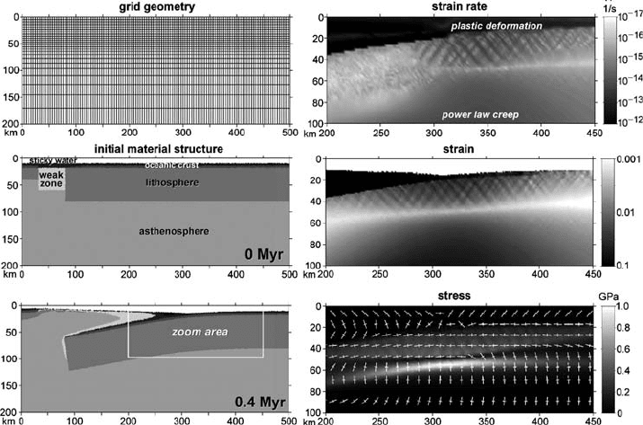
Fig. 17.1 Numerical grid (a) initial conditions (b) and results (c)–(f) of numerical
experiment for visco-elasto-plastic slab bending during spontaneously retreating
subduction. Model resolution is 251 ×51 nodal points with 100 000 randomly
distributed markers. Grid resolution (a) is non-uniform in the vertical direction
(each second grid line is shown). Cooling ages of the left and right plates in (b)
are 1 Myr and 70 Myr respectively. (d), (e) and (f) shows numerical results for
the zoomed area outlined in (c). Note that plastic deformation along faults in (d)
is deactivated in the subducted portion of the slab. White crosses in (f) show the
orientation of the principal stress axes; long and short branches of the crosses show
extension and shortening directions, respectively. Lithospheric and asthenospheric
mantle in (b) and (c) do not differ in properties (dry mantle, Table 17.2), different
colours for them are used for better visualisation of slab bending. Results are
computed with the code Subducting_slab_bending.m.
these faults are similar to the dimensions of the rupture area of intermediate-depth
earthquakes.
The numerical setup for bending of a subducting slab is rather simple
(Fig. 17.1(a)(b)), but requires relatively high resolution (at least 2 ×2kmintheslab
bending area to adequately resolve the bending-related normal faults) and realis-
tic pressure-, temperature- and stress-dependent visco-elasto-plastic rheology. One
way to investigate spontaneous slab subduction and bending consists of using an
initial setup for subduction initiation across a pre-existing transform fault (Hall
et al., 2003). The experiment begins with two plates of different ages, juxtaposed
along a transform fault (cf. light grey weak zone in Fig. 17.1(b)) with low plastic

17.4 Visco-elasto-plastic slab bending 275
strength (sin(ϕ) =0), which creates favourable conditions for spontaneous initi-
ation of subduction and concurrent slab bending. The vertical thermal structure
of the plates is computed according to the cooling of a semi-infinite half-space
(Turcotte and Schubert, 2002)
T (d) = T
1
+
(
T
0
− T
1
)
1 − erf
d
2
√
κτ
, (17.1)
where T
0
= 273 K is the temperature at the surface for both plates, T
1
= 1700 K
is the temperature at the bottom of the model, d is the depth in meters below the
surface, κ is thermal diffusivity (10
−6
m
2
/s) and τ is the age in seconds of the
plates.
Bending is driven by strong negative buoyancy of the older plate while the
weak fault allows initial displacement, which results in the spontaneous retreating
subduction. To ensure self-sustaining, one-sided subduction, the weak, hydrated
upper oceanic crust (basalts, sediments) is present atop the slab providing stable
lubrication against the moving and cooling overriding plate (e.g., Sobolev and
Babeyko, 2005; Gerya et al., 2008a). On the other hand, a weak upper layer
present above the crust (‘sticky water’, η =10
18
Pa s, ρ =1000 kg/m
3
) provides a
free-surface-like condition which is essential for a natural slab bending to occur.
The validity of the weak layer approach to approximate the free surface has recently
been tested and proven (Schmeling et al., 2008) with the use of a large variety of
numerical techniques (including our methodology based on conservative finite-
differences and marker-in-cell techniques) and comparison with analogue models.
The thickness of the weak layer should be at least 4–5 grid cells and its viscosity
should be at least 100 times less than that of the underlying lithosphere. For regional
models like the one presented here, optimal parameters for the weak layer are 10–
15 km and 10
18
–10
19
Pa s (larger thickness and lower viscosity of this layer may
require shorter time steps to avoid oscillations of numerical solution for velocity
and pressure fields in the weak layer).
Figure 17.1 shows the results of a numerical experiment for spontaneous
bending of a retreating subducting plate obtained with the code Subducting_
slab_bending.m. The deformation pattern in the bending slab is distinct
(Fig. 17.1(d)): the top of the slab is subjected to intense plastic deformation with
localised faults while the bottom of the slab deforms in a ductile way (i.e. by the
temperature- and stress-activated dislocation creep, cf. Table 17.1) with enhance-
ment of the deformation (see dark zone in the lower part of Fig. 17.1(d)) due to
high stresses (see, light zones in Fig. 17.1(f)) in the bending area. The plastic fault-
ing and ductile deformation fields are characterised by extension and compression
in a horizontal direction, respectively (see orientation of stress principal axes in
Fig. 17.1(f)). These two fields are clearly separated by the narrow, non-deforming

276 Design of 2D numerical geodynamic models
middle plane of the slab (see light zone inside the slab in Fig. 17.1(e)) which is char-
acterised by small deviatoric stresses (see dark zone inside the slab in Fig. 17.1(f)).
The penetration depth of faults (10–50 km) (Fig. 17.1(e)) is in agreement with the
observational constraints (Ranero et al., 2003, 2005). Results of the experiment
show that a slab with a free upper surface can easily be bent by its own weight,
thereby triggering spontaneous retreating subduction. Bending is facilitated by (i)
lowered pressure in the extension region, which favours deep penetration of faults
and (ii) by large stresses in the compression region, which produces a local lowering
of the slab viscosity due to the power-law nature of ductile creep.
17.5 Retreating oceanic subduction
This model is comparable to the previous one, but the model size is much larger to
allow a longer slab retreat and deeper penetration. To avoid a significant increase
in a number of grid points, one can employ a non-uniformly spaced grid with
a high-resolution area that moves together with the trench (Gerya et al., 2008a;
Nikolaeva et al., 2008). The grid spacing increases gradually away from the area of
high resolution by a constant factor F at every nodal point (cf. vertical resolution
in the lower part of Fig. 17.1(a)). In order to compute this incremental factor, the
following formula is solved iteratively
F =
1 +
D
b
1 −
1
F
1/N
, (17.2)
where D is the distance that should be covered by N non-uniform grid steps and
b is the grid spacing in the high resolution area (i.e. grid spacing from which the
incremental increase should start). In order to avoid sharp changes in the numerical
solution, the grid modification can be done at every time step. Re-meshing has
no major effect on the algorithm since in our marker-in-cell approach, relative
positions of markers and nodes change at every time step anyway. Also, nodal
values of physical parameters (including temperature changes) are only used for
updating properties at the moving markers. Therefore, an Eulerian node has no
‘memory’ and can be shifted between two time steps. In addition, since the model
is much deeper than the previous one and pressure varies significantly from the
top to the bottom, we should take into account the activation volume of dislocation
creep.
The activation volume V
a
for olivine creep (this creep is assumed to represent
the mantle rheology, Tables 17.1, 17.2) varies from 0 (wet olivine) to 17 cm
3
(dry
olivine) (e.g. Ranalli, 1995). Intermediate values of V
a
are possible as water content
in the mantle varies. Subduction model development can be notably affected by
this parameter (e.g. Mishin et al., 2008) and, therefore, investigating some range