Halderman J.D., Linder J. Automotive Fuel and Emissions Control Systems
Подождите немного. Документ загружается.

FUEL PUMPS, LINES, AND FILTERS 251
20
10
0
30
40
50
60
70
80
90
100
110
120
130
PSI
20
10
0
30
40
50
60
70
80
90
100
110
120
130
PSI
SMALL HOSE
LESS VOLUME
SAME PRESSURE
LARGER HOSE
MORE VOLUME
SAME PRESSURE
REGULATOR
REGULATOR
FROM
FUEL
PUMP
FROM
FUEL
PUMP
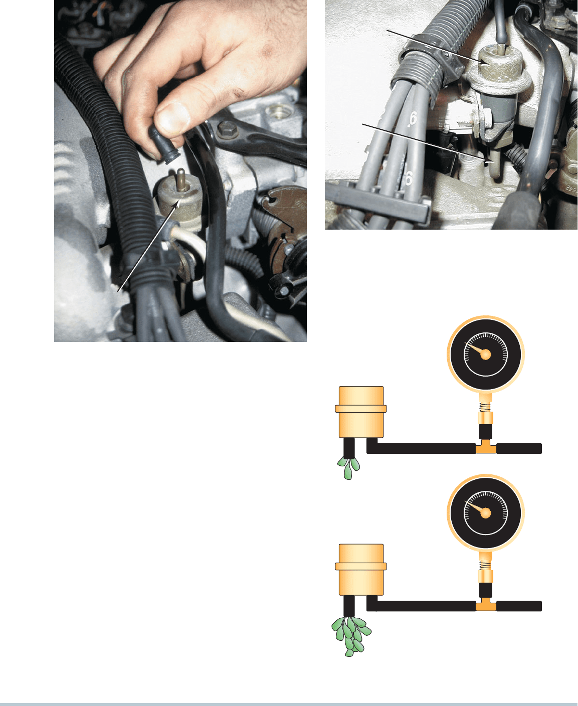
FIGURE 19–26 A fuel-pressure reading does not confirm that
there is enough fuel volume for the engine to operate correctly.
TESTING FUEL PUMP VOLUME Fuel pressure alone is
not enough for proper engine operation.
SEE FIGURE 19–26 .
Sufficient fuel capacity (flow) should be at least 2 pints (1 liter)
every 30 seconds or 1 pint in 15 seconds. Fuel flow specifica-
tions are usually expressed in gallons per minute. A typical
specification would be 0.5 gallon per minute or more. Volume
testing is shown in
SEE FIGURE 19–27 .
All fuel must be filtered to prevent dirt and impurities
from damaging the fuel system components and/or engine.
The first filter is inside the gas tank and is usually not re-
placeable separately but is attached to the fuel pump (if the
pump is electric) and/or fuel gauge sending unit. The replace-
able fuel filter is usually located between the fuel tank and
the fuel rail or inlet to the fuel-injection system. Most vehicle
manufacturers state in service information when to replace
the fuel filter. Most newer vehicles that use returnless-type
fuel-injection systems do not have replaceable filters as they
are built into the fuel pump module assembly. (Check the
FUEL
PRESSURE
REGULATOR
FIGURE 19–24 If the vacuum hose is removed from the
fuel-pressure regulator when the engine is running, the fuel
pressure should increase. If it does not increase, then the fuel
pump is not capable of supplying adequate pressure or the
fuel-pressure regulator is defective. If gasoline is visible in the
vacuum hose, the regulator is leaking and should be replaced.
FUEL
PRESSURE
REGULATOR
FUEL
RETURN
LINE TO
TANK
FIGURE 19–25 Fuel should be heard returning to the fuel
tank at the fuel return line if the fuel pump and fuel-pressure
regulator are functioning correctly.
252 CHAPTER 19
vehicle manufacturer’s recommendations for exact time and
mileage intervals.)
If the fuel filter becomes partially clogged, the following are
likely to occur:
1. There will be low power at higher engine speeds. The ve-
hicle usually will not go faster than a certain speed (engine
acts as if it has a built-in speed governor).
2. The engine will cut out or miss on acceleration, especially
when climbing hills or during heavy-load acceleration.
A weak or defective fuel pump can also be the cause of the
symptoms just listed. If an electric fuel pump for a fuel-injected
engine becomes weak, additional problems include the following:
1. The engine may be hard to start.
2. There may be a rough idle and stalling.
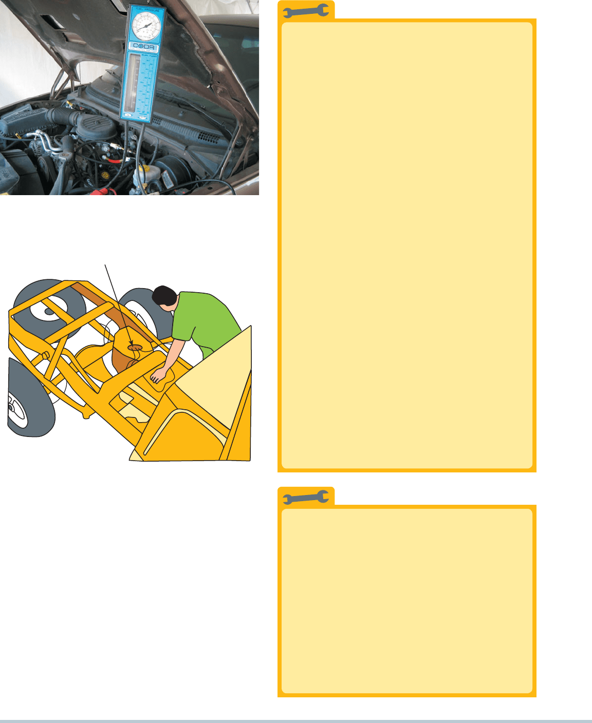
FIGURE 19–27 A fuel system tester connected in series in
the fuel system so all of the fuel used flows through the meter,
which displays the rate flow and the fuel pressure.
TECH TIP
Quick and Easy Fuel Volume Test
Testing for pump volume involves using a special-
ized tester or a fuel-pressure gauge equipped with a
hose to allow the fuel to be drawn from the system
into a container with volume markings to allow for a
volume measurement. This test can be hazardous
because of flammable gasoline vapors. An alterna-
tive test involves connecting a fuel-pressure gauge
to the system with the following steps:
STEP 1 Start the engine and observe the fuel-
pressure gauge. The reading should be
within factory specifications (typically
between 35 PSI and 45 PSI).
STEP 2 Remove the hose from the fuel-pressure
regulator. The pressure should increase if
the system uses a demand-type regulator.
STEP 3 Rapidly accelerate the engine while watching
the fuel-pressure gauge. If the fuel volume is
okay, the fuel pressure should not drop more
than 2 PSI. If the fuel pressure drops more
than 2 PSI, replace the fuel filter and retest.
STEP 4 After replacing the fuel filter, accelerate the
engine and observe the pressure gauge.
If the pressure drops more than 2 PSI,
replace the fuel pump.
NOTE: The fuel pump could still be
delivering less than the specified
volume of fuel, but as long as the
volume needed by the engine is met,
the pressure will not drop. If, how-
ever, the vehicle is pulling a heavy
load, the demand for fuel volume may
exceed the capacity of the pump.
FUEL PUMP
FIGURE 19–28 Removing the bed from a pickup truck
makes gaining access to the fuel pump a lot easier.
TECH TIP
Remove the Bed to Save Time?
The electric fuel pump is easier to replace on many
General Motors pickup trucks if the bed is removed.
Access to the top of the fuel tank, where the access
hole is located, for the removal of the fuel tank sender
unit and pump is restricted by the bottom of the
pickup truck bed. Rather than drop the tank, it is often
much easier to use an engine hoist or a couple of other
technicians to lift the bed from the frame after remov-
ing only a few fasteners.
SEE FIGURE 19–28.
CAUTION: Be sure to clean around the fuel
pump opening so that dirt or debris does not
enter the tank when the fuel pump is removed.
FUEL PUMPS, LINES, AND FILTERS 253
3. There may be erratic shifting of the automatic transmission
as a result of engine missing due to lack of fuel pump pres-
sure and/or volume.
CAUTION: Be certain to consult the vehicle manufac-
turer’s recommended service and testing procedures
before attempting to test or replace any component of
a high-pressure electronic fuel-injection system.
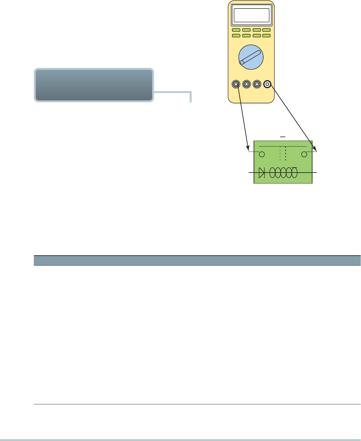
B+
86
F
U
EL P
U
MP RELAY
85
6.62 A
TO
FUEL
PUMP
8730
FIGURE 19–29 Hookup for testing fuel pump current draw
on any vehicle equipped with a fuel pump relay.
Fuel Pump Current Draw Table
Amperage Reading Expected Value Amperage Too High Amperage Too Low
Throttle-body
fuel-injection
engines
2 to 5 amps • Check the fuel filter.
• Check for restrictions in other
fuel line areas.
• Replace the fuel pump.
• Check for a high-resistance connection.
• Check for a high-resistance ground fault.
• Replace the fuel pump.
Port fuel-injection
engines
4 to 8 amps • Check the fuel filter.
• Check for restrictions in other
fuel line areas.
• Replace the fuel pump.
• Check for a high-resistance connection.
• Check for a high-resistance ground fault.
• Replace the fuel pump.
Turbo engines 6 to 10 amps • Check the fuel filter.
• Check for restrictions in other
fuel line areas.
• Replace the fuel pump.
• Check for a high-resistance connection.
• Check for a high-resistance ground fault.
• Replace the fuel pump.
GM CPI truck
engines
8 to 12 amps • Check the fuel filter.
• Check for restrictions in other
fuel line areas.
• Replace the fuel pump.
• Check for a high-resistance connection.
• Check for a high-resistance ground fault.
• Replace the fuel pump.
Another test that can and should be performed on a fuel pump
is to measure the current draw in amperes. This test is most
often performed by connecting a digital multimeter set to read
DC amperes and test the current draw.
SEE FIGURE 19–29
for the hookup for vehicles equipped with a fuel pump relay.
Compare the reading to factory specifications. See the chart for
an example of typical fuel pump current draw readings.
NOTE: Testing the current draw of an electric fuel pump
may not indicate whether the pump is good. A pump that
is not rotating may draw normal current.
Using a mini clamp on ammeter is a quick and easy way to
measure fuel pump current. Clamp the inductive probe around
a wire to the fuel pump or add a fused jumper wire to replace
the fuel pump fuse. Start the engine and read the meter display.
FUEL PUMP CURRENT
DRAW TEST
254 CHAPTER 19
The following recommendations should be followed whenever
replacing an electric fuel pump.
Clean around the fuel pump retainer area before remov-
ing the fuel pump assembly.
The fuel pump strainer (sock) should be replaced with the
new pump.
If the original pump had a defector shield, it should al-
ways be used to prevent fuel return bubbles from block-
ing the inlet to the pump.
Always check the interior of the fuel tank for evidence of
contamination or dirt.
Double-check that the replacement pump is correct for
the application.
Check that the wiring and electrical connectors are clean
and tight.
FUEL PUMP
REPLACEMENT
Fuel Supply-Related Symptom Guide
Problem Possible Causes
Pressure too
high after
engine
start-up.
1. Defective fuel-pressure regulator
2. Restricted fuel return line
3. Excessive system voltage
4. Wrong fuel pump
Pressure too low
after engine
start-up.
1. Stuck-open pressure regulator
2. Low voltage
3. Poor ground
4. Plugged fuel filter
5. Faulty inline fuel pump
6. Faulty in-tank fuel pump
7. Partially clogged filter sock
8. Faulty hose coupling
9. Leaking fuel line
10. Wrong fuel pump
11. Leaking pulsator
12. Restricted accumulator
13. Faulty pump check valves
14. Faulty pump installation
Pressure drops
off with key
on/engine off.
With key off, the
pressure
does not hold.
1. Leaky pulsator
2. Leaking fuel pump coupling hose
3. Faulty fuel pump (check valves)
4. Faulty pressure regulator
5. Leaking fuel injector
6. Faulty installation
7. Lines leaking
5. Most fuel lines are made of nylon plastic.
6. Electric fuel pump types include: roller cell, gerotor, and
turbine.
7. Fuel filters remove particles that are 10 to 20 microns or
larger in size and should be replaced regularly.
8. Fuel pumps can be tested by checking the following:
•
Pressure
•
Volume
•
Specified current draw
1. The fuel delivery system includes the following items:
•
Fuel tank
•
Fuel pump
•
Fuel filter(s)
•
Fuel lines
2. A fuel tank is either constructed of steel with a tin plating
for corrosion resistance or polyethylene plastic.
3. Fuel tank filler tubes contain an antisiphoning device.
4. Accident and rollover protection devices include check
valves and inertia switches.
SUMMARY
4. Where are the fuel filters located in the fuel system?
5. What accident and rollover devices are installed in a fuel
delivery system?
6. What three methods can be used to test a fuel pump?
1. What are the two materials used to construct fuel tanks?
2. What are the three most commonly used pump designs?
3. What is the proper way to disconnect and connect plastic
fuel line connections?
REVIEW QUESTIONS

FUEL PUMPS, LINES, AND FILTERS 255
7. Most fuel filters are designed to remove particles larger
than ______________ .
a. 10 microns c. 70 microns
b. 20 microns d. 100 microns
8. The amperage draw of an electric fuel pump is higher than
specified. All of the following are possible causes except
______________.
a. Corroded electrical connections at the pump motor
b. Clogged fuel filter
c. Restriction in the fuel line
d. Defective fuel pump
9. A fuel pump is being replaced for the third time. Technician
A says that the gasoline could be contaminated. Techni-
cian B says that wiring to the pump could be corroded.
Which technician is correct?
a. Technician A only
b. Technician B only
c. Both Technicians A and B
d. Neither Technician A nor B
10. A fuel filter has been accidentally installed backwards.
What is the most likely result?
a. Nothing will be noticed
b. Reduced fuel economy
c. Lower power at higher engine speeds and loads
d. Fuel system pulsation noises may be heard
1. The first fuel filter in the sock inside the fuel tank normally
filters particles larger than ______________ .
a. 0.001 to 0.003 in. c. 10 to 20 microns
b. 0.01 to 0.03 in. d. 70 to 100 microns
2. If it is tripped, which type of safety device will keep the
electric fuel pump from operating?
a. Rollover valve c. Antisiphoning valve
b. Inertia switch d. Check valve
3. Fuel lines are constructed from ______________ .
a. Seamless steel tubing
b. Nylon plastic
c. Copper and/or aluminum tubing
d. Both a and b
4. What prevents the fuel pump inside the fuel tank from
catching the gasoline on fire?
a. Electricity is not used to power the pump.
b. No air is around the motor brushes.
c. Gasoline is hard to ignite in a closed space.
d. All of the above
5. A good fuel pump should be able to supply how much fuel
per minute?
a. 1/4 pint c. 1 pint
b. 1/2 pint
d. 0.5 to 0.8 gallon
6. Technician A says that fuel pump modules are spring
loaded so that they can be compressed to fit into the open-
ing. Technician B says that they are spring loaded to allow
for expansion and contraction of plastic fuel tanks. Which
technician is correct?
a. Technician A only
b. Technician B only
c. Both Technicians A and B
d. Neither Technician A nor B
CHAPTER QUIZ

256 CHAPTER 20
chapter
FUEL-INJECTION
COMPONENTS
AND OPERATION
20
OBJECTIVES: After studying Chapter 20 , the reader should be able to: • Prepare for ASE Engine Performance (A8)
certification test content area “C” (Fuel, Air Induction, and Exhaust Systems Diagnosis and Repair). • Describe how a port
fuel-injection system works. • Describe the fuel injection modes of operation. • Discuss the purpose and function of the
fuel-pressure regulator. • Discuss central port injection (CPI) systems. • Explain how a stepper motor works. • List the types
of fuel-injection systems.
KEY TERMS: Demand delivery system (DDS) 263 • Electronic air control (EAC) 267 • Electronic returnless fuel
system (ERFS) 262 • Flare 267 • Fuel rail 264 • Gang fired 259 • Idle speed control (ISC) motor 268 • Mechanical
returnless fuel system (MRFS) 263 • Nonchecking 262 • Port fuel injection 256 • Pressure control valve (PCV) 263
• Pressure vent valve (PVV) 263 • Sequential fuel injection (SFI) 259 • Throttle-body injection (TBI) 256
Electronic fuel-injection systems use the Powertrain control
module (PCM) to control the operation of fuel injectors and
other functions based on information sent to the PCM from the
various sensors. Most electronic fuel-injection systems share
the following:
1. Electric fuel pump (usually located inside the fuel tank)
2. Fuel-pump relay (usually controlled by the computer)
3. Fuel-pressure regulator (mechanically operated spring-
loaded rubber diaphragm maintains proper fuel pressure)
4.
Fuel-injector nozzle or nozzles
SEE FIGURE 20–1 . Most electronic fuel-injection systems use
the computer to control the following aspects of their operation:
1. Pulsing the fuel injectors on and off. The longer the
injectors are held open, the greater the amount of fuel
injected into the cylinder.
2. Operating the fuel-pump relay circuit. The computer usu-
ally controls the operation of the electric fuel pump located
inside (or near) the fuel tank. The computer uses signals
from the ignition switch and RPM signals from the ignition
module or system to energize the fuel-pump relay circuit.
NOTE: This is a safety feature because if the engine
stalls and the tachometer (engine speed) signal is lost,
the computer will shut off (deenergize) the fuel-pump
relay and stop the fuel pump.
ELECTRONIC FUEL-
INJECTION OPERATION
Computer-controlled fuel-injection systems are normally reli-
able systems if the proper service procedures are followed. Fuel-
injection systems use the gasoline flowing through the injectors to
lubricate and cool the injector electrical windings and pintle valves.
NOTE: The fuel does not actually make contact with
the electrical windings because the injectors have
O-rings at the top and bottom of the winding spool to
keep fuel out.
There are two types of electronic fuel-injection systems:
Throttle-body-injection (TBI) type. A TBI system deliv-
ers fuel from a nozzle(s) into the air above the throttle
plate.
SEE FIGURE 20–2 .
Port fuel-injection type. A port fuel-injection design uses
a nozzle for each cylinder, and the fuel is squirted into the
intake manifold about 2 to 3 inches (70 to 100mm) from
the intake valve.
SEE FIGURE 20–3 .
Fuel-injection computer systems require a method for measur-
ing the amount of air the engine is breathing in, in order to match
the correct fuel delivery. There are two basic methods used:
1. Speed density
2. Mass airflow
The speed-density method does not require an air quantity
sensor but rather calculates the amount of fuel required by the
SPEED-DENSITY FUEL-
INJECTION SYSTEMS
FUEL-INJECTION COMPONENTS AND OPERATION 257
FUEL
TANK
FUEL
FILTER
FUEL "RAIL" (FUEL TUBE
SUPPLYING FUEL TO ALL
INJECTORS)
VACUUM
HOSE
INJECTORS
(NOZZLES)
WIRING TO
TANK UNIT
ELECTRIC
IN-TANK
FUEL PUMP
FUEL
RETURN
LINE
FUEL
PICKUP
SOCK
FUEL-PRESSURE
REGULATOR
FUEL
FLOAT FOR
FUEL LEVEL
GAUGE
SUPPLY LINE
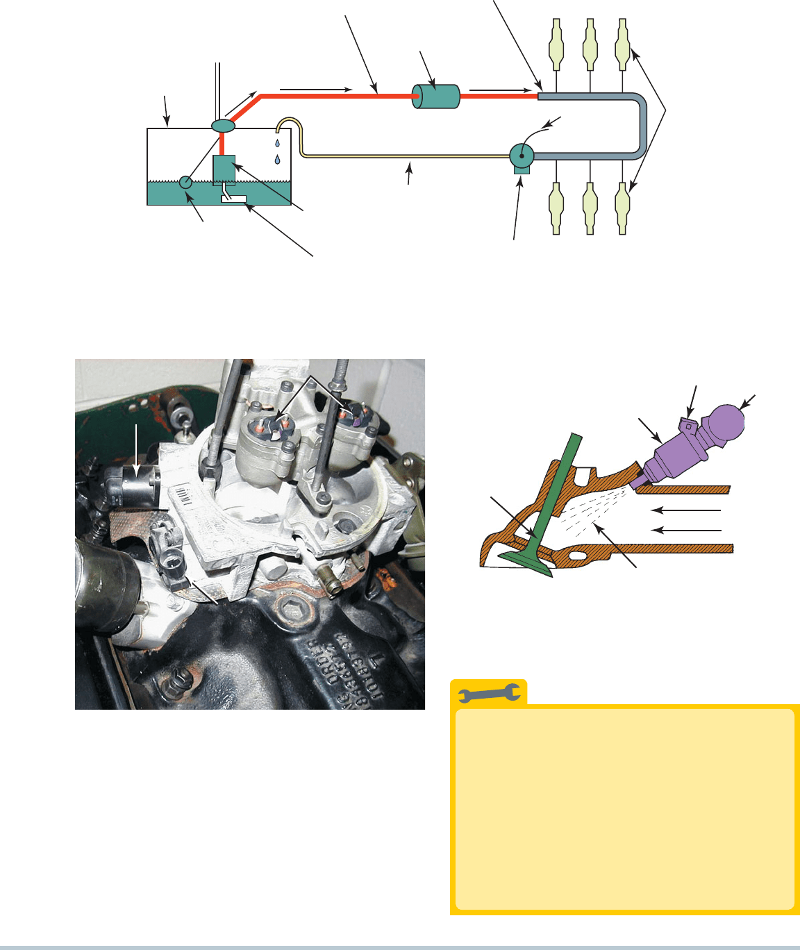
FIGURE 20–1 Typical port fuel-injection system, indicating the location of various components. Notice that the fuel-pressure
regulator is located on the fuel return side of the system. The computer does not control fuel pressure but does control the
operation of the electric fuel pump (on most systems) and the pulsing on and off of the injectors.
IAC
INJECTOR NOZZLES
TP SENSOR
FIGURE 20–2 A dual-nozzle TBI unit on a Chevrolet 4.3-L
V-6 engine. The fuel is squirted above the throttle plate, where
the fuel mixes with air before entering the intake manifold.
INTAKE
VALVE
FUEL
RAIL
AIR ONLY
INJECTOR
SPRAY PATTERN
FUEL INJECTOR
(NOZZLE)
WIRING CONNECTOR
(TO COMPUTER)
FIGURE 20–3 A typical port fuel-injection system squirts fuel
into the low pressure (vacuum) of the intake manifold, about
2 to 3 inches (70 to 100 mm) from the intake valve.
engine. The computer uses information from sensors such as
the MAP and TP to calculate the needed amount of fuel:
MAP sensor. The value of the intake (inlet) manifold
pressure (vacuum) is a direct indication of engine load.
TP sensor. The position of the throttle plate and its rate
of change are used as part of the equation to calculate
the proper amount of fuel to inject.
Two Must-Dos
For long service life of the fuel system, always do the
following:
1. Avoid operating the vehicle on a near-empty tank
of fuel. The water or alcohol that may be in the tank
becomes more concentrated when the fuel level
is low. Dirt that settles near the bottom of the fuel
tank can be drawn through the fuel system and
cause damage to the pump and injector nozzles.
2. Replace the fuel filter at regular service intervals.
TECH TIP
258 CHAPTER 20
Temperature sensors. Both engine coolant tempera-
ture (ECT) and intake air temperature (IAT) are used to
calculate the density of the air and the need of the engine
for fuel. A cold engine (low-coolant temperature) requires
a richer air-fuel mixture than a warm engine.
On speed-density systems, the computer calculates the
amount of air in each cylinder by using manifold pressure and
engine rpm. The amount of air in each cylinder is the major
factor in determining the amount of fuel needed. Other sen-
sors provide information to modify the fuel requirements. The
formula used to determine the injector pulse width (PW) in
milliseconds (ms) is the following:
Injector pulse width MAP/BARO RPM/maximum rpm
The formula is modified by values from other sensors,
including the following:
Throttle position (TP)
Engine coolant temperature (ECT)
Intake air temperature (IAT)
Oxygen sensor (O2S) voltage
Adaptive memory
A fuel injector delivers atomized fuel into the airstream,
where it is instantly vaporized. All throttle-body (TB) fuel-injection
systems and many multipoint (port) injection systems use the
speed-density method of fuel calculation.
The formula used by fuel-injection systems that use a mass
airflow (MAF) sensor to calculate the injection base pulse
width is the following:
Injector pulse width airflow/rpm
The formula is modified by other sensor values, such as
the following:
Throttle position
Engine coolant temperature
Barometric pressure
Adaptive memory
NOTE: Many 4-cylinder engines do not use a MAF sensor
because, due to the time interval between intake events,
some reverse airflow can occur in the intake manifold.
The MAF sensor would “read” this flow of air as being
additional air entering the engine, giving the PCM in-
correct airflow information. Therefore, most 4-cylinder
engines use the speed-density method of fuel control.
MASS AIRFLOW FUEL-
INJECTION SYSTEMS
The computer controls injector pulses in one of two ways:
Synchronized
Nonsynchronized
If the system uses a synchronized mode, the injector
pulses once for each distributor reference pulse. In some ve-
hicles, when dual injectors are used in a synchronized system,
the injectors pulse alternately. In a nonsynchronized system, the
injectors are pulsed once during a given period (which varies
according to calibration) completely independent of distributor
reference pulses.
The injector always opens the same distance, and the fuel
pressure is maintained at a controlled value by the pressure reg-
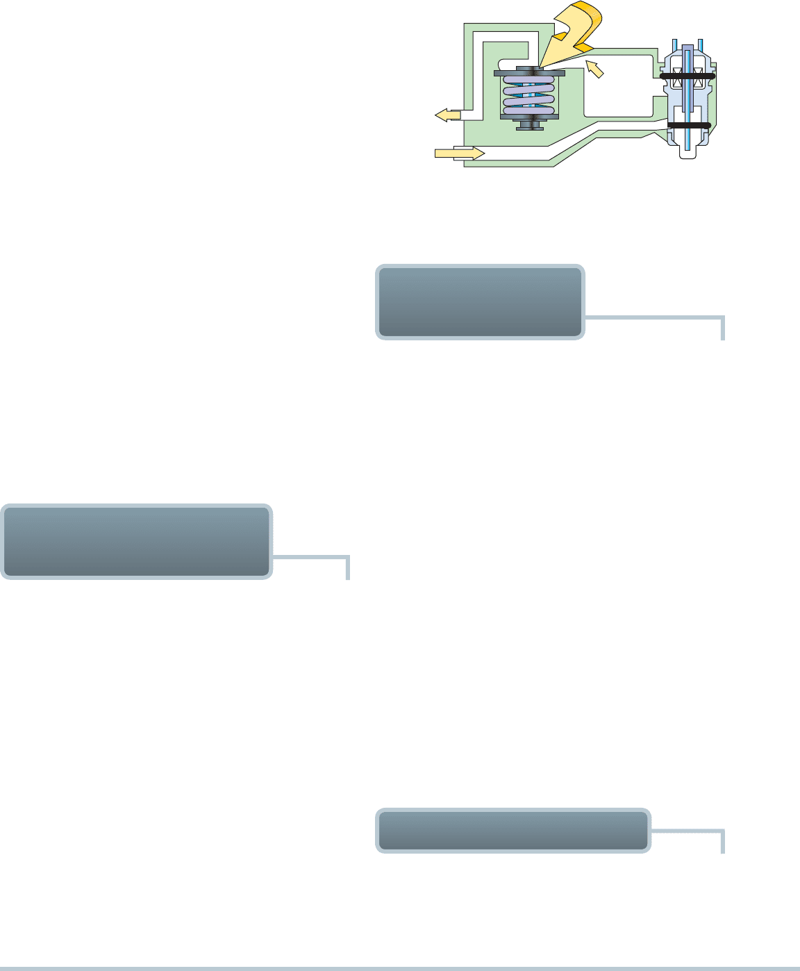
ulator. The regulators used on throttle-body injection systems
are not connected to a vacuum like many port fuel-injection sys-
tems. The strength of the spring inside the regulator determines
at what pressure the valve is unseated, sending the fuel back to
the tank and lowering the pressure.
SEE FIGURE 20–4 . The
amount of fuel delivered by the injector depends on the amount
of time (on-time) that the nozzle is open. This is the injector pulse
width—the on-time in milliseconds that the nozzle is open.
The PCM commands a variety of pulse widths to supply
the amount of fuel that an engine needs at any specific moment:
A long pulse width delivers more fuel.
A short pulse width delivers less fuel.
THROTTLE-BODY
INJECTION
FUEL
RETURN
TO TANK
FUEL IN
TO THROTTLE
BODY
EXCESS
FUEL TO
REGULATOR
INJECTOR
(BOTTOM FEED)
PRESSURE
REGULATOR
FIGURE 20–4 The tension of the spring in the fuel-pressure
regulator determines the operating pressure on a throttle-body
fuel-injection unit.
PORT FUEL INJECTION
The advantages of port fuel-injection design also are related to
characteristics of intake manifolds:
Fuel distribution is equal to all cylinders because each
cylinder has its own injector.
SEE FIGURE 20–5 .
FUEL-INJECTION COMPONENTS AND OPERATION 259
How Do the Sensors Affect the Pulse Width?
The base pulse width of a fuel-injection system is
primarily determined by the value of the MAF or
MAP sensor and engine speed (RPM). However, the
PCM relies on the input from many other sensors to
modify the base pulse width as needed:
• TP Sensor. This sensor causes the PCM to com-
mand up to 500% (five times) the base pulse width
if the accelerator pedal is depressed rapidly to the
floor. It can also reduce the pulse width by about
70% if the throttle is rapidly closed.
• ECT. The value of this sensor determines the tem-
perature of the engine coolant, helps determine
the base pulse width, and can account for up to
60% of the determining factors.
• BARO. The BARO sensor compensates for altitude
and adds up to about 10% under high- pressure
conditions and subtracts as much as 50% from
the base pulse width at high altitudes.
• IAT. The intake air temperature is used to modify
the base pulse width based on the temperature of
the air entering the engine. It is usually capable of
adding as much as 20% if very cold air is entering
the engine or reducing the pulse width by up to
20% if very hot air is entering the engine.
• O2S. This is one of the main modifiers to the base
pulse width and can add or subtract up to about
20% to 25% or more, depending on the oxygen
sensor activity.
?
FREQUENTLY ASKED QUESTION
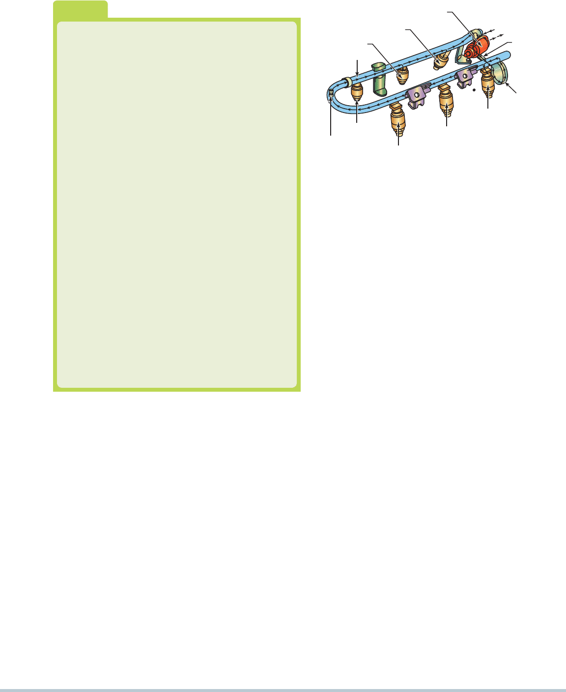
FUEL RAIL
INJECTOR
INJECTOR
FUEL-PRESSURE REGULATOR
FUEL-
PRESSURE
TAP
INJECTOR
INJECTOR
INJECTOR
INJECTOR
PULSE
DAMPENER
FUEL INLET
TUBE
TO FUEL
RETURN LINE
FR
O
M
FUEL FEED
LINE
FIGURE 20–5 The injectors receive fuel and are supported
by the fuel rail.
The fuel is injected almost directly into the combustion
chamber, so there is no chance for it to condense on the
walls of a cold intake manifold.
Because the manifold does not have to carry fuel to
properly position a TBI unit, it can be shaped and sized
to tune the intake airflow to achieve specific engine per-
formance characteristics.
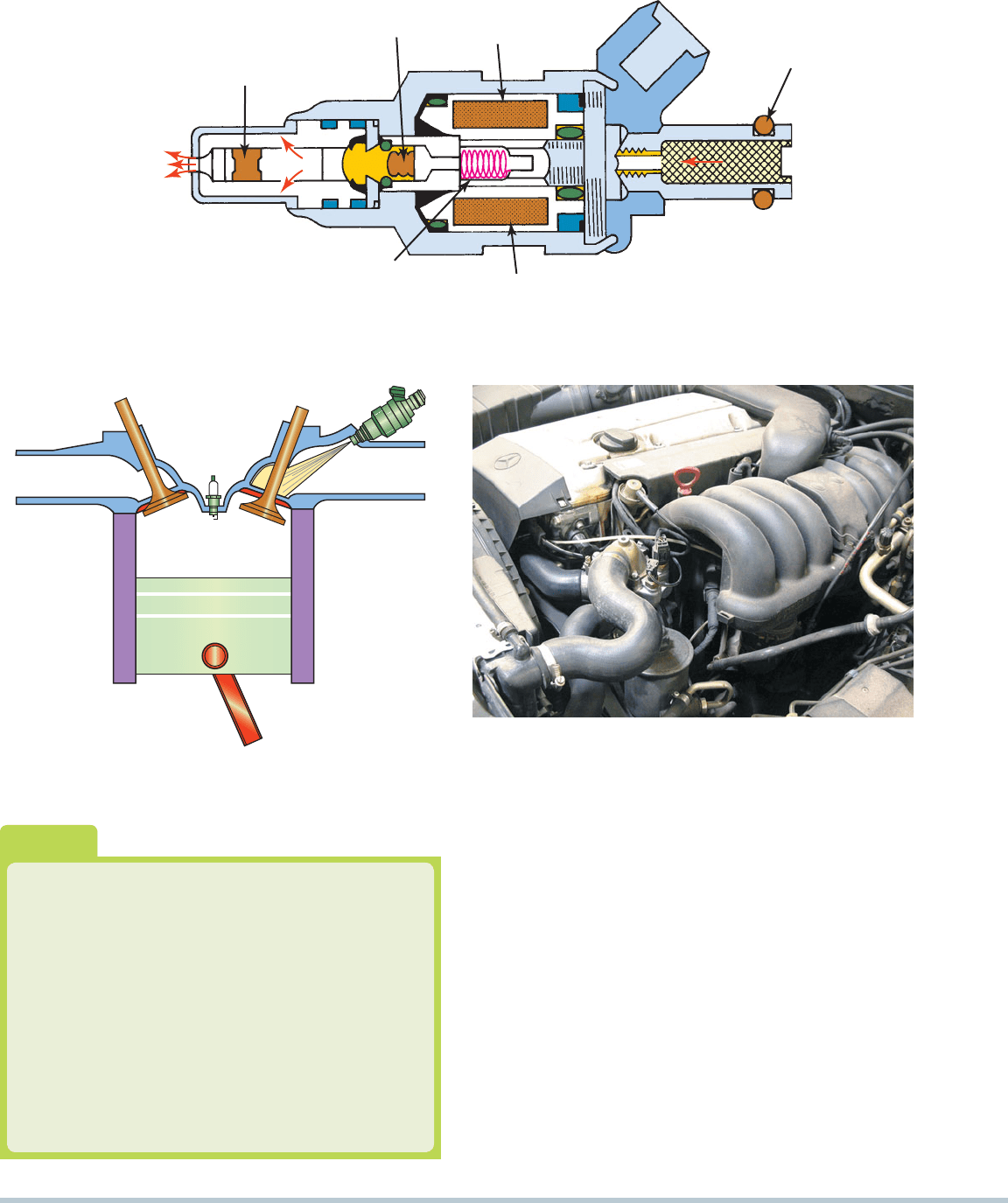
An EFI injector is simply a specialized solenoid.
SEE
FIGURE 20–6 . It has an armature winding to create a magnetic
field, and a needle (pintle), a disc, or a ball valve. A spring holds
the needle, disc, or ball closed against the valve seat, and when
energized, the armature winding pulls open the valve when it
receives a current pulse from the powertrain control module
(PCM). When the solenoid is energized, it unseats the valve to
inject fuel.
Electronic fuel-injection systems use a solenoid-
operated injector to spray atomized fuel in timed pulses into
the manifold or near the intake valve.
SEE FIGURE 20–7 .
Injectors may be sequenced and fired in one of several ways,
but their pulse width is determined and controlled by the
engine computer.
Port systems have an injector for each cylinder, but they
do not all fire the injectors in the same way. Domestic systems
use one of three ways to trigger the injectors:
Grouped double-fire
Simultaneous double-fire
Sequential
GROUPED DOUBLE-FIRE This system divides the injec-
tors into two equalized groups. The groups fire alternately; each
group fires once each crankshaft revolution, or twice per four-
stroke cycle. The fuel injected remains near the intake valve and
enters the engine when the valve opens. This method of pulsing
injectors in groups is sometimes called gang fired .
SIMULTANEOUS DOUBLE-FIRE This design fires all of
the injectors at the same time once every engine revolution: two
pulses per four-stroke cycle. Many port fuel-injection systems
on 4-cylinder engines use this pattern of injector firing. It is easier
for engineers to program this system and it can make relatively
quick adjustments in the air-fuel ratio, but it still requires the
intake charge to wait in the manifold for varying lengths of time.
SEQUENTIAL Sequential firing of the injectors according to
engine firing order is the most accurate and desirable method of
regulating port fuel injection. However, it is also the most complex
and expensive to design and manufacture. In this system, the
injectors are timed and pulsed individually, much like the spark
plugs are sequentially operated in firing order of the engine. This
system is often called sequential fuel injection, or SFI. Each
cylinder receives one charge every two crankshaft revolutions,
just before the intake valve opens. This means that the mixture
is never static in the intake manifold, and mixture adjustments
can be made almost instantaneously between the firing of one
injector and the next. A camshaft position sensor (CMP) signal or
a special distributor reference pulse informs the PCM when the
number 1 cylinder is on its compression stroke. If the sensor fails
or the reference pulse is interrupted, some injection systems shut
down, while others revert to pulsing the injectors simultaneously.
260 CHAPTER 20
NEEDLE
VALVE
COIL
WINDINGS
PLUNGER
INLET
WIRING
TERMINAL
INJECTION
O-RING
SEAL
PLUNGER SPRING
(CLOSES NEEDLE
VALVE)
COIL
WINDINGS
FIGURE 20–6 Cross section of a typical port fuel-injection nozzle assembly. These injectors are serviced as an assembly only;
no part replacement or service is possible except for replacement of external O-ring seals.
FIGURE 20–7 Port fuel injectors spray atomized fuel into the
intake manifold about 3 inches (75 mm) from the intake valve.
How Can It Be Determined if the Injection
System Is Sequential?
Look at the color of the wires at the injectors. If a se-
quentially fired injector is used, then one wire color (the
pulse wire) will be a different color for each injector. The
other wire is usually the same color because all injectors
receive voltage from some source. If a group- or batch-
fired injection system is being used, then the wire colors
will be the same for the injectors that are group fired.
For example, a V-6 group-fired engine will have three in-
jectors with a pink and blue wire (power and pulse), and
the other three will have pink and green wires.
?
FREQUENTLY ASKED QUESTION
FIGURE 20–8 A port fuel-injected engine that is equipped
with long, tuned intake manifold runners.
The major advantage of using port injection instead of the
simpler throttle-body injection is that the intake manifolds on
port fuel-injected engines only contain air, not a mixture of air
and fuel. This allows the engine design engineer the opportunity
to design long, “tuned” intake-manifold runners that help the
engine produce increased torque at low engine speeds.
SEE
FIGURE 20–8 .
NOTE: Some port fuel-injection systems used on en-
gines with four or more valves per cylinder may use two
injectors per cylinder. One injector is used all the time,
and the second injector is operated by the computer
when high engine speed and high-load conditions are
detected by the computer. Typically, the second injector
injects fuel into the high-speed intake ports of the mani-
fold. This system permits good low-speed power and
throttle responses as well as superior high-speed power.