Halderman J.D., Linder J. Automotive Fuel and Emissions Control Systems
Подождите немного. Документ загружается.

ELECTRONIC THROTTLE CONTROL SYSTEM 281
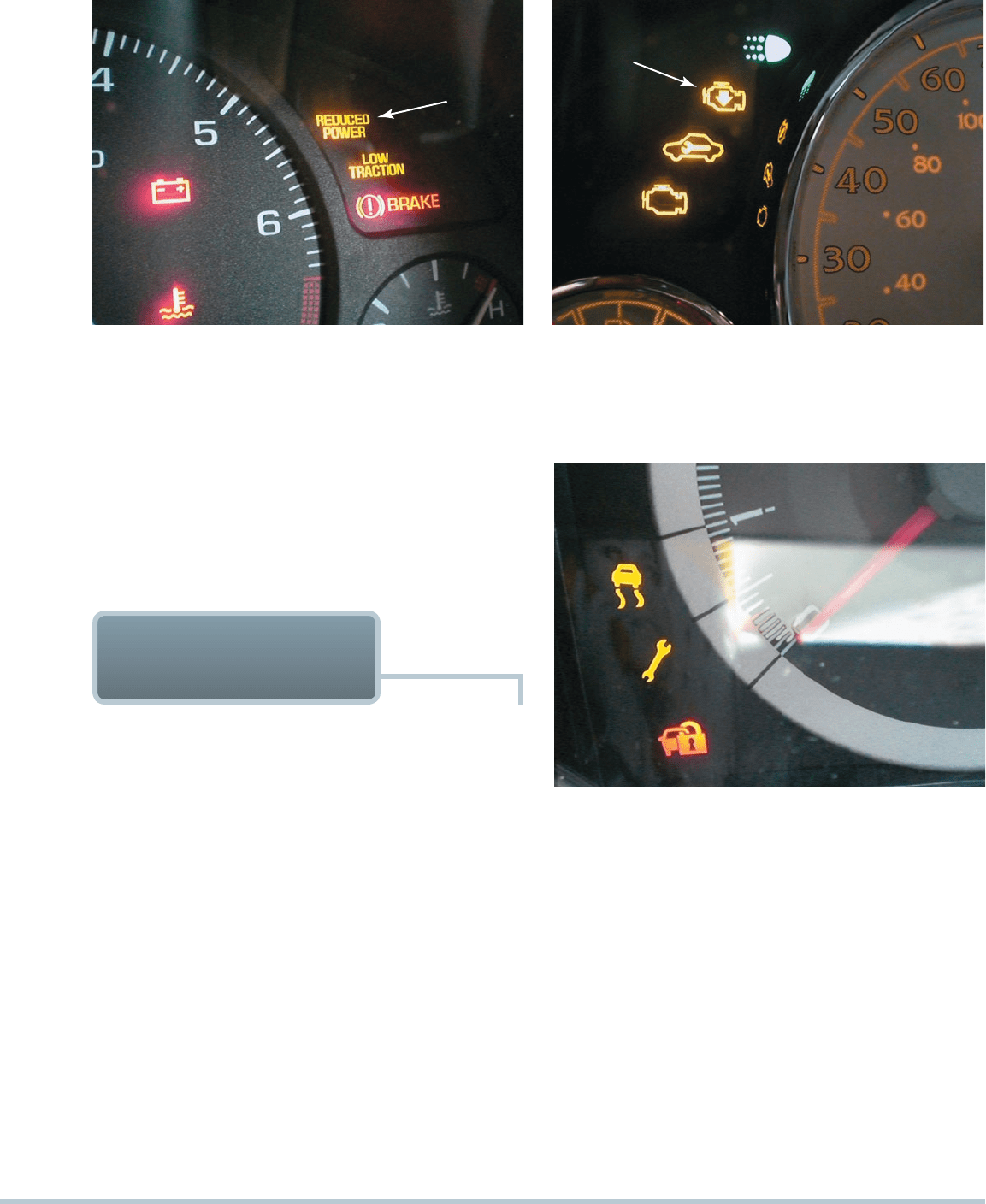
FIGURE 22–9 A wrench symbol warning lamp on a Ford
vehicle. The symbol can also be green.
HALL-EFFECT TP SENSORS Some vehicle manufactur-
ers, Honda, for example, use a noncontact Hall-effect TP sen-
sor. Because there is not physical contact, this type of sensor
is less likely to fail due to wear.
(a)
FIGURE 22–8 (a) A “reduced power” warning light indicates a fault with the electronic throttle control (ETC) system on some
General Motors vehicles. (b) A symbol showing an engine with an arrow pointing down is used on some General Motors vehicles
to indicate a fault with the ETC system.
(b)
FAULT MODE ETC systems can have faults like any
other automatic system. Because of the redundant sensors
in accelerator pedal position (APP) sensors and TP sensor,
many faults result in a “limp home” situation instead of a
total failure. The limp home mode is also called the “fail-safe
mode” and indicates the following actions performed by
thePCM:
Engine speed is limited to the default speed (about 1,200
to 1,600 RPM).
There is slow or no response when the accelerator pedal
is depressed.
The cruise control system is disabled.
A diagnostic trouble code (DTC) is set.
An ETC warning lamp on the dash will light. The warning
lamp may be labeled differently, depending on the vehicle
manufacturer. Examples include the following:
General Motors vehicle—Reduced power lamp ( SEE
FIGURE 22–8 )
Ford—Wrench symbol (amber or green) ( SEE
FIGURE 22–9 )
DIAGNOSIS OF ETC
SYSTEMS
Chrysler—Red lightning bolt symbol ( SEE
FIGURE 22–10 )
The engine will run and can be driven slowly. This limp-in
mode operation allows the vehicle to be driven off of the
road and to a safe location.
The ETC may enter the limp-in mode if any of the following
has occurred:
Low battery voltage has been detected
PCM failure
One TP and the MAP sensor have failed
Both TP sensors have failed
The ETC actuator motor has failed
The ETC throttle spring has failed
282 CHAPTER 22
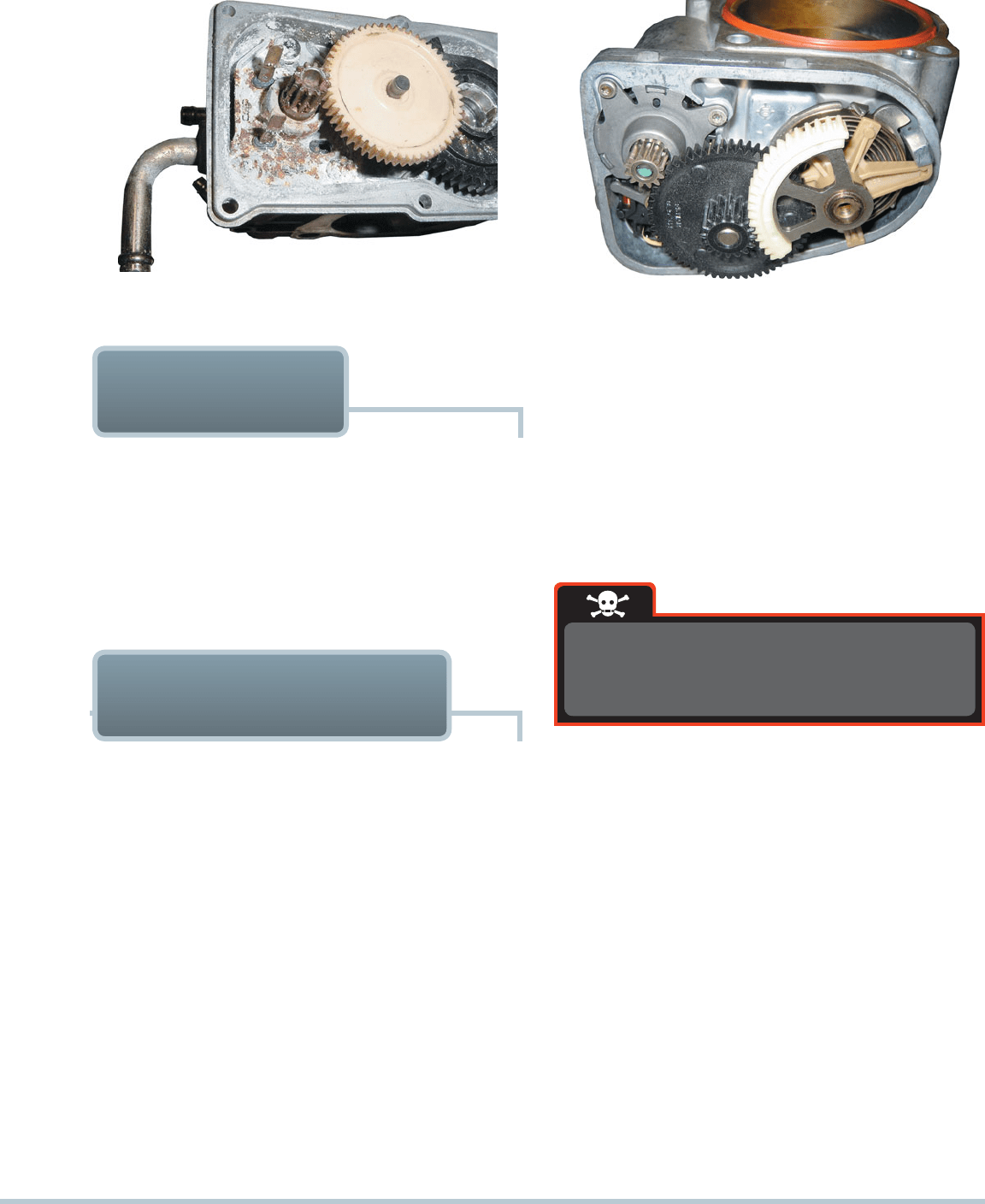
FIGURE 22–11 The throttle plate stayed where it was moved
by the technician, which indicates that there is a problem with
the electronic throttle body control assembly.
FIGURE 22–10 A symbol used on a Chrysler vehicle indicat-
ing a fault with the electronic throttle control (ETC).
The High-Idle Toyota
The owner of a Toyota Camry complained that the
engine would idle at over 1,200 RPM compared
with a normal 600 to 700 RPM. The vehicle would
also not accelerate. Using a scan tool, a check for
DTCs showed one code: P2101—“TAC motor
circuit low.”
Checking service information led to the inspec-
tion of the ETC throttle body assembly. With the
ignition key out of the ignition and the inlet air duct
off the throttle body, the technician used a screwdriver
to gently push to see if the throttle plate worked:
Normal operation —The throttle plate should move and
then spring back quickly to the default position.
Abnormal operation —If the throttle plate stays where
it is moved or does not return to the default posi-
tion, there is a fault with the throttle body assembly.
SEE FIGURE 22–11 .
Solution: The technician replaced the throttle
body assembly with an updated version, and proper
engine operation was restored. The technician disas-
sembled the old throttle body and found it was cor-
roded inside because of moisture entering the unit
through the vent hose.
SEE FIGURE 22–12 .
REAL WORLD FIX
VACUUM LEAKS The ETC system is able to compensate
for many vacuum leaks. A vacuum leak at the intake manifold
for example will allow air into the engine that is not measured
by the mass airflow sensor. The ETC system will simply move
the throttle as needed to achieve the proper idle speed to com-
pensate for the leak.
DIAGNOSTIC PROCEDURE If a fault occurs in the ETC
system, check service information for the specified procedure
to follow for the vehicle being checked. Most vehicle service
information includes the following steps:
STEP 1 Verify the customer concern.
STEP 2 Use a factory scan tool or an aftermarket scan tool
with original equipment capability and check for DTCs.
STEP 3 If there are stored DTCs, follow service information
instructions for diagnosing the system.
STEP 4 If there are no stored DTCs, check scan tool data for
possible fault areas in the system.
SCAN TOOL DATA Scan data related to the ETC system
can be confusing. Typical data and the meaning include the
following:
APP indicated angle. The scan tool will display a per-
centage ranging from 0% to 100%. When the throttle is
released, the indicated angle should be 0%. When the
throttle is depressed to wide open, the reading should
indicate 100%.
TP desired angle. The scan tool will display a percent-
age ranging from 0% to 100%. This represents the
desired throttle angle as commanded by the driver of
the vehicle.
TP indicated angle. The TP indicated angle is the angle
of the measured throttle opening, and it should agree
with the TP desired angle.
TP sensors 1 and 2. The scan tool will display “agree”
or “disagree.” If the PCM or throttle actuator control
(TAC) module receives a voltage signal from one of
the TP sensors that is not in the proper relationship
to the other TP sensor, the scan tool will display
“disagree.”
ELECTRONIC THROTTLE CONTROL SYSTEM 283
FIGURE 22–12 A corroded electronic throttle control (ETC)
assembly shown with the cover removed.
THROTTLE BODY CLEANING PROCEDURE Before
attempting to clean a throttle body on an engine equipped with
an ETC system, be sure that the ignition key is out of the vehicle
and the ready light is off if working on a Toyota/Lexus hybrid
electric vehicle to avoid the possibility of personal injury.
FIGURE 22–13 Notice the small motor gear on the left drives
a larger plastic gear (black), which then drives the small gear in
mesh with the section of a gear attached to the throttle plate.
This results in a huge torque increase from the small motor
and helps explain why it could be dangerous to insert a finger
into the throttle body assembly.
On some vehicles, such as many Chrysler vehicles, the opera-
tion of the ETC can be tested using a factory or factory-level
scan tool. To perform this test, use the “throttle follower test”
procedure as shown on the scan tool. An assistant is needed to
check that the throttle plate is moving as the accelerator pedal
is depressed. This test cannot be done normally because the
PCM does not normally allow the throttle plate to be moved un-
less the engine is running.
ETC THROTTLE
FOLLOWER TEST
ETC-RELATED PERFORMANCE ISSUES The only ser-
vice that an ETC system may require is a cleaning of the throttle
body. Throttle body cleaning is a routine service procedure on
port fuel-injected engines and is still needed when the throttle
is being opened by an electric motor rather than a throttle cable
tied to a mechanical accelerator pedal. The throttle body may
need cleaning if one or more of the following symptoms are
present:
Lower-than-normal idle speed
Rough idle
Engine stalls when coming to a stop (called a coast-
down stall )
If any of the above conditions exists, a throttle body clean-
ing will often correct these faults.
CAUTION: Some vehicle manufacturers add a nonstick
coating to the throttle assembly and warn that cleaning
could remove this protective coating. Always follow the
vehicle manufacturer’s recommended procedures.
SERVICING ELECTRONIC
THROTTLE SYSTEMS
The electric motor that operates the throttle
plate is strong enough to cut off a finger.
SEE
FIGURE 22–13 .
WARNING
To clean the throttle, perform the following steps:
STEP 1 With the ignition off and the key removed from the
ignition, remove the air inlet hose from the throttle
body.
STEP 2 Spray throttle body cleaner onto a shop cloth.
STEP 3 Open the throttle body and use the shop cloth to re-
move the varnish and carbon deposits from the throttle
body housing and throttle plate.
CAUTION: Do not spray cleaner into the throt-
tle body assembly. The liquid cleaner could
flow into and damage the throttle position (TP)
sensors.
STEP 4 Reinstall the inlet hose being sure that there are no air
leaks between the hose and the throttle body assembly.
STEP 5 Start the engine and allow the PCM to learn the correct
idle. If the idle is not correct, check service information
for the specified procedures to follow to perform a
throttle relearn.

284 CHAPTER 22
THROTTLE BODY RELEARN PROCEDURE Wheninstall-
ing a new throttle body or PCM or sometimes after cleaning
the throttle body, the throttle position has to be learned by the
PCM. After the following conditions have been met, a typical
throttle body relearn procedure for a General Motors vehicle
includes the following:
Accelerator pedal released
Battery voltage higher than 8 volts
Vehicle speed must be zero
Engine coolant temperature (ECT) higher than 40°F (5°C)
and lower than 212°F (100°C)
Intake air temperature (IAT) higher than 40°F (5°C)
No throttle DTCs set
If all of the above conditions are met, perform the follow-
ing steps:
STEP 1 Turn the ignition on (engine off) for 30 seconds.
STEP 2 Turn the ignition off and wait 30 seconds.
Start the engine and the idle learn procedure should cause
the engine to idle at the correct speed.
4. What component parts are included in an ETC system?
5. What is the default or limp-in position of the throttle plate?
6. What dash warning light indicates a fault with the ETC
system?
1. What parts can be deleted if an engine uses an electronic
throttle control (ETC) system instead of a conventional ac-
celerator pedal and cable to operate the throttle valve?
2. How can the use of an ETC system improve fuel economy?
3. How is the operation of the throttle different on a system
that uses an ETC system compared with a conventional
mechanical system?
REVIEW QUESTIONS
2. The throttle plate is spring loaded to hold the throttle
slightly open how far?
a. 3% to 5%
b. 8% to 10%
c. 16% to 20%
d. 22% to 28%
1. The use of an electronic throttle control (ETC) system al-
lows the elimination of all except ______________ .
a. Accelerator pedal
b. Mechanical throttle cable (most systems)
c. Cruise control actuator
d. Idle air control
CHAPTER QUIZ
4. Limp-in mode is commanded if there is a major fault in the
system, which can allow the vehicle to be driven enough
to be pulled off the road to safety.
5. The diagnostic procedure for the ETC system includes
verifying the customer concern, using a scan tool to check
for DTCs, and checking the value of the TP and APP sen-
sors.
6. Servicing the ETC system includes cleaning the throttle
body and throttle plate.
1. Using an electronic throttle control (ETC) system on an
engine has many advantages over a conventional method
that uses a mechanical cable between the accelerator
pedal and the throttle valve.
2. The major components of an ETC system include the
following:
•
Accelerator pedal position (APP) sensor
•
ETC actuator motor and spring
•
Throttle position (TP) sensor
•
Electronic control unit
3. The TP sensor is actually two sensors that share the 5-volt
reference from the PCM and produce opposite signals as
a redundant check.
SUMMARY

ELECTRONIC THROTTLE CONTROL SYSTEM 285
8. A technician is checking the operation of the ETC system
by depressing the accelerator pedal with the ignition in the
on (run) position (engine off). What is the most likely result
if the system is functioning correctly?
a. The throttle goes to wide open when the accelerator
pedal is depressed all the way.
b. There is no throttle movement.
c. The throttle will open partially but not all of the way.
d. The throttle will perform a self-test by closing and then
opening to the default position.
9. With the ignition off and the key out of the ignition, what
should happen if a technician uses a screwdriver and pushes
gently on the throttle plate in an attempt to open the valve?
a. Nothing. The throttle should be kept from moving by
the motor, which is not energized with the key off.
b. The throttle should move and stay where it is moved
and not go back unless moved back.
c. The throttle should move and then spring back to the
home position when released.
d. The throttle should move closed but not open further
than the default position.
10. The throttle body may be cleaned (if recommended by the
vehicle manufacturer) if what conditions are occurring?
a. Coast-down stall
b. Rough idle
c. Lower-than-normal idle speed
d. Any of the above
3. The throttle plate actuator motor is what type of electric
motor?
a. Stepper motor c. AC motor
b. DC motor d. Brushless motor
4. The actuator motor is controlled by the PCM through what
type of circuit?
a. Series c. H-bridge
b. Parallel d. Series-parallel
5. When does the PCM perform a self-test of the ETC system?
a. During cruise speed when the throttle is steady
b. During deceleration
c. During acceleration
d. When the ignition switch is first rotated to the on posi-
tion before the engine starts
6. The throttle position sensor used in the throttle body as-
sembly of an ETC system is what type?
a. Single potentiometer
b. Two potentiometers that read in the opposite direction
c. Hall-effect sensor
d. Either b or c
7. A green wrench symbol is displayed on the dash. What
does this mean?
a. A fault in the ETC in a Ford has been detected.
b. A fault in the ETC in a Honda has been detected.
c. A fault in the ETC in a Chrysler has been detected.
d. A fault in the ETC in a General Motors vehicle has
been detected.
286 CHAPTER 23
chapter
FUEL-INJECTION SYSTEM
DIAGNOSIS AND SERVICE
23
OBJECTIVES: After studying Chapter 23 , the reader should be able to: • Prepare for ASE Engine Performance (A8)
certification test content area “C” (Fuel, Air Induction, and Exhaust Systems Diagnosis and Repair). • Explain how to test the fuel
injection system using a scan tool. • Explain how to check a fuel-pressure regulator. • Describe how to test fuel injectors.
• Explain how to diagnose electronic fuel-injection problems. • Describe how to service the fuel-injection system.
KEY TERMS: Graphing multimeter (GMM) 287 • Idle air control counts 288 • Idle air control (IAC) 295 • Noid light 289
• Peak-and-hold injector 294 • Pressure transducer 287 • Saturation 294
FIGURE 23–1 If the vacuum hose is removed from the fuel-
pressure regulator when the engine is running, the fuel pres-
sure should increase. If it does not increase, then the fuel
pump is not capable of supplying adequate pressure or the
fuel-pressure regulator is defective. If gasoline is visible in the
vacuum hose, the regulator is leaking and should be replaced.
Most port fuel-injected engines use a vacuum hose connected to
the fuel-pressure regulator. At idle, the pressure inside the intake
manifold is low (high vacuum). Manifold vacuum is applied above
the diaphragm inside the fuel-pressure regulator. This reduces
the pressure exerted on the diaphragm and results in a lower,
about 10 PSI (69 kPa), fuel pressure applied to the injectors. To
test a vacuum-controlled fuel-pressure regulator, follow these
steps:
1. Connect a fuel-pressure gauge to monitor the fuel pressure.
2. Locate the fuel-pressure regulator and disconnect the
vacuum hose from the regulator.
NOTE: If gasoline drips out of the vacuum hose
when removed from the fuel-pressure regula-
tor, the regulator is defective and will require
replacement.
3. With the engine running at idle speed, reconnect the
vacuum hose to the fuel-pressure regulator while watch-
ing the fuel-pressure gauge. The fuel pressure should drop
(about 10 PSI, or 69 kPa) when the hose is reattached to
the regulator.
4. Using a hand-operated vacuum pump, apply vacuum
(20 in. Hg) to the regulator. The regulator should hold
PORT FUEL-INJECTION
PRESSURE REGULATOR
DIAGNOSIS
vacuum. If the vacuum drops, replace the fuel-pressure
regulator.
SEE FIGURE 23–1 .
NOTE: Some vehicles do not use a vacuum-regulated
fuel-pressure regulator. Many of these vehicles use a
regulator located inside the fuel tank that supplies a
constant fuel pressure to the fuel injectors.
FUEL-INJECTION SYSTEM DIAGNOSIS AND SERVICE 287
Check the positive crankcase ventilation (PCV) valve
forproper operation or replacement as needed.
SEE
FIGURE 23–3.
NOTE: The use of an incorrect PCV valve can cause
a rough idle or stalling.
Check all fuel-injection electrical connections for
corrosion or damage.
Check for gasoline at the vacuum port of the
fuel-pressure regulator if the vehicle is so equipped.
Gasoline in the vacuum hose at the fuel-pressure
regulator indicates that the regulator is defective
andrequires replacement.
FIGURE 23–3 A clogged PCV system caused the engine oil
fumes to be drawn into the air cleaner assembly. This is what
the technician discovered during a visual inspection.
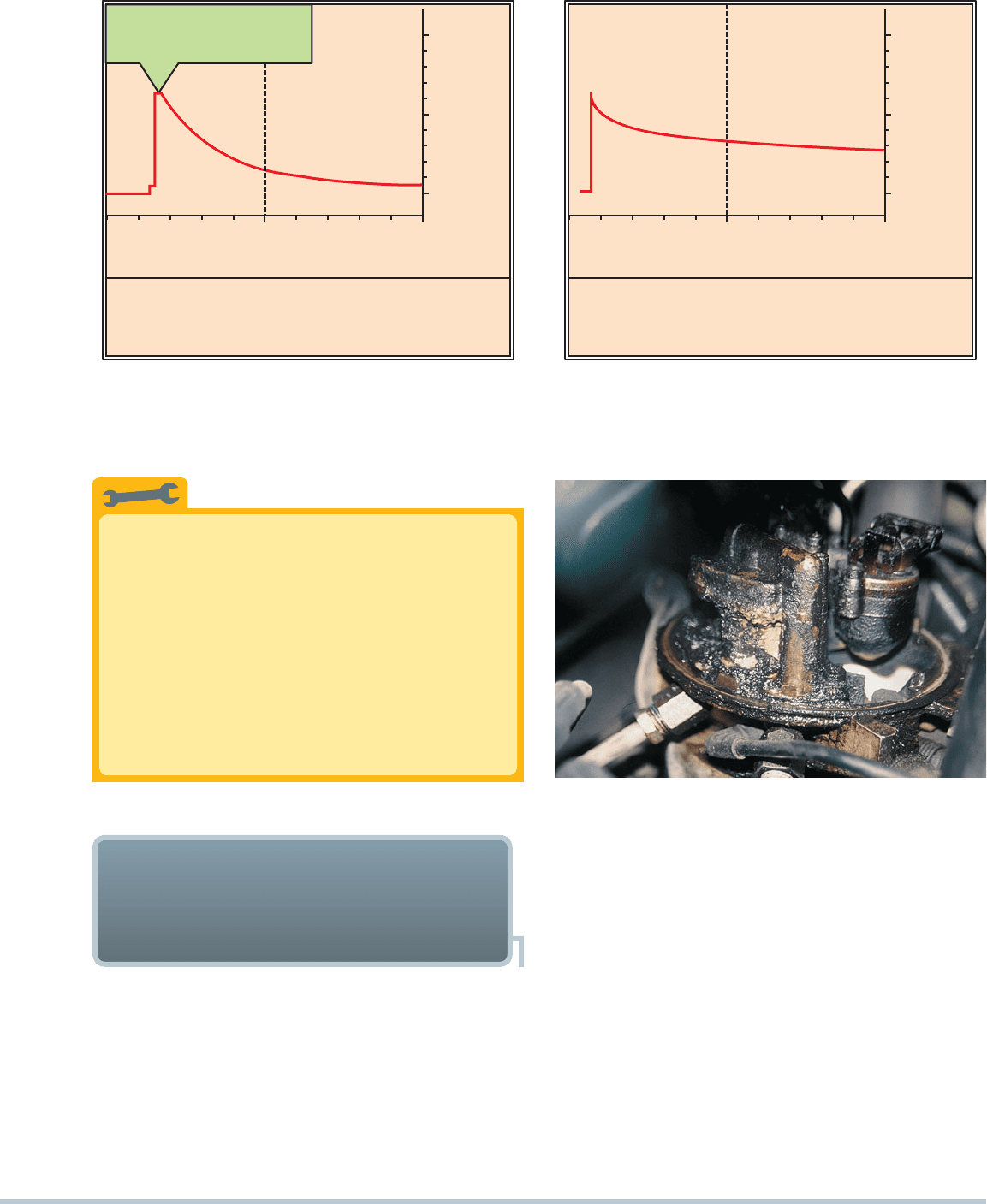
Pressure Transducer Fuel-Pressure Test
Using a pressure transducer and a graphing
multimeter (GMM) or digital storage oscilloscope
(DSO) allows the service technician to view the fuel
pressure over time.
SEE FIGURE 23–2(a). Note
that the fuel pressure dropped from 15 PSI to 6 PSI
on a TBI-equipped vehicle after just one minute.
Anormal pressure holding capability is shown in
FIGURE 23–2(b) when the pressure dropped only
about 10% after 10 minutes on a port fuel-injection
system.
TECH TIP
KOEO
2-SEC. FUEL PUMP PULSE
LEAKING REGULATOR
FUEL PRESSURE DROP AFTER 1 MINUTE
8 PSI
1 m
100
0
60 PSI
(
a
)
32.6
10 m
100
0
28.0 PSI
(b)
FIGURE 23–2 (a) A fuel-pressure graph after key on, engine off (KOEO) on a TBI system. (b) Pressure drop after 10 minutes on a
normal port fuel-injection system.
All fuel-injection systems require the proper amount of clean
fuel delivered to the system at the proper pressure and the cor-
rect amount of filtered air. The following items should be care-
fully inspected before proceeding to more detailed tests:
Check the air filter and replace as needed.
Check the air induction system for obstructions.
Check the conditions of all vacuum hoses. Replace any
hose that is split, soft (mushy), or brittle.
DIAGNOSING ELECTRONIC
FUEL-INJECTION PROBLEMS
USING VISUAL INSPECTION
288 CHAPTER 23
FIGURE 23–4 All fuel injectors should make the same sound
with the engine running at idle speed. A lack of sound indi-
cates a possible electrically open injector or a break in the wir-
ing. A defective computer could also be the cause of a lack of
clicking (pulsing) of the injectors.
FUEL-
PRESSURE
REGULATOR
FUEL
RETURN
LINE TO
TANK
FIGURE 23–5 Fuel should be heard returning to the fuel tank
at the fuel return line if the fuel-pump and fuel-pressure regu-
lator are functioning correctly.
SCAN TOOL VACUUM
LEAK DIAGNOSIS
If a vacuum (air) leak occurs on an engine equipped with a
speed-density type of fuel injection, the extra air would cause
the following to occur:
The idle speed increases because of the extra air just as
if the throttle pedal were depressed.
The MAP sensor reacts to the increased air from the
vacuum leak as an additional load on the engine.
Stethoscope Fuel-Injection Test
A commonly used test for injector operation is to
listen to the injector using a stethoscope with the
engine operating at idle speed.
SEE FIGURE 23–4.
All injectors should produce the same clicking sound.
If any injector makes a clunking or rattling sound, it
should be tested further or replaced. With the engine
still running, place the end of the stethoscope probe
to the return line from the fuel-pressure regulator.
SEE FIGURE 23–5. Fuel should be heard flow-
ing back to the fuel tank if the fuel-pump pressure is
higher than the fuel-regulator pressure. If no sound
of fuel is heard, then either the fuel pump or the fuel-
pressure regulator is at fault.
TECH TIP
Quick and Easy Leaking Injector Test
Leaking injectors may be found by disabling the igni-
tion, unhooking all injectors, and checking exhaust
for hydrocarbons (HC) using a gas analyzer while
cranking the engine (maximum HC = 300 PPM).
TECH TIP
The computer increases the injector pulse width slightly
longer because of the signal from the MAP sensor.
The air-fuel mixture remains unchanged.
The idle air control (IAC) counts will decrease, thereby at-
tempting to reduce the engine speed to the target idle speed
stored in the computer memory.
SEE FIGURE 23–6.
Therefore, one of the best indicators of a vacuum leak on a
speed-density fuel-injection system is to look at the IAC counts
or percentage. Normal IAC counts or percentage is usually
15to 25. A reading of less than 5 indicates a vacuum leak.
If a vacuum leak occurs on an engine equipped with a
mass airflow type of fuel-injection system, the extra air causes
the following to occur:
The engine will operate leaner than normal because the
extra air has not been measured by the MAF sensor.
The idle speed will likely be lower because of the leaner-
than-normal air-fuel mixture.
The IAC counts or percentage will often increase in an
attempt to return the engine speed to the target speed
stored in the computer.
FUEL-INJECTION SYSTEM DIAGNOSIS AND SERVICE 289
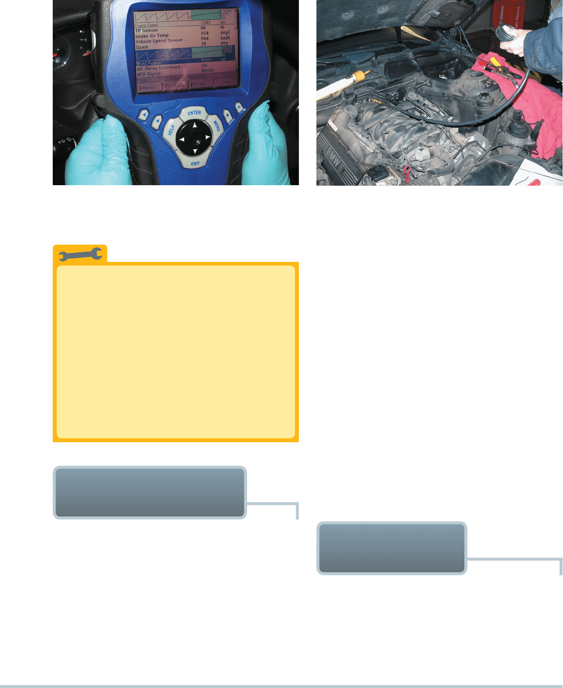
FIGURE 23–6 Using a scan tool to check for idle air control
(IAC) counts or percentage as part of a diagnostic routine.
FIGURE 23–7 Checking the fuel pressure using a fuel-
pressure gauge connected to the Schrader valve.
okay; if the drop is greater, then there is a possible prob-
lem with the following:
The check valve in the fuel pump
Leaking injectors, lines, or fittings
A defective (leaking) fuel-pressure regulator
To determine which unit is defective, perform the following:
Reenergize the electric fuel pump.
Clamp the fuel supply line and wait 10 minutes (see Cau-
tion box). If the pressure drop does not occur, replace the
fuel pump. If the pressure drop still occurs, continue with
the next step.
Repeat the pressure buildup of the electric pump and
clamp the fuel return line. If the pressure drop time is now
okay, replace the fuel-pressure regulator.
If the pressure drop still occurs, one or more of the injec-
tors is leaking. Remove the injectors with the fuel rail and
hold over paper. Replace those injectors that drip one or
more drops after 10 minutes with pressurized fuel.
CAUTION: Do not clamp plastic fuel lines. Connect shut-
off valves to the fuel system to shut off supply and return
lines.
SEE FIGURE 23–8.
No Spark, No Squirt
Most electronic fuel-injection computer systems
use the ignition primary (pickup coil or crank sen-
sor) pulse as the trigger for when to inject (squirt)
fuel from the injectors (nozzles). If this signal were
not present, no fuel would be injected. Because
this pulse is also necessary to trigger the module to
create a spark from the coil, it can be said that “no
spark” could also mean “no squirt.” Therefore, if the
cause of a no-start condition is observed to be a
lack of fuel injection, do not start testing or replacing
fuel-system components until the ignition system is
checked for proper operation.
TECH TIP
PORT FUEL-INJECTION
SYSTEM DIAGNOSIS
To determine if a port fuel-injection system—including the fuel
pump, injectors, and fuel-pressure regulator—is operating cor-
rectly, take the following steps:
1. Attach a fuel-pressure gauge to the Schrader valve on the
fuel rail.
SEE FIGURE 23–7.
2. Turn the ignition key on or start the engine to build up the
fuel-pump pressure (to about 35 to 45 PSI).
3. Wait 20 minutes and observe the fuel pressure retained
in the fuel rail and note the PSI reading. The fuel pressure
should not drop more than 20 PSI (140 kPa) in 20 minutes.
If the drop is less than 20 PSI in 20 minutes, everything is
TESTING FOR AN
INJECTOR PULSE
One of the first checks that should be performed when diagnos-
ing a no-start condition is whether the fuel injectors are being
pulsed by the computer. Checking for proper pulsing of the in-
jector is also important in diagnosing a weak or dead cylinder.
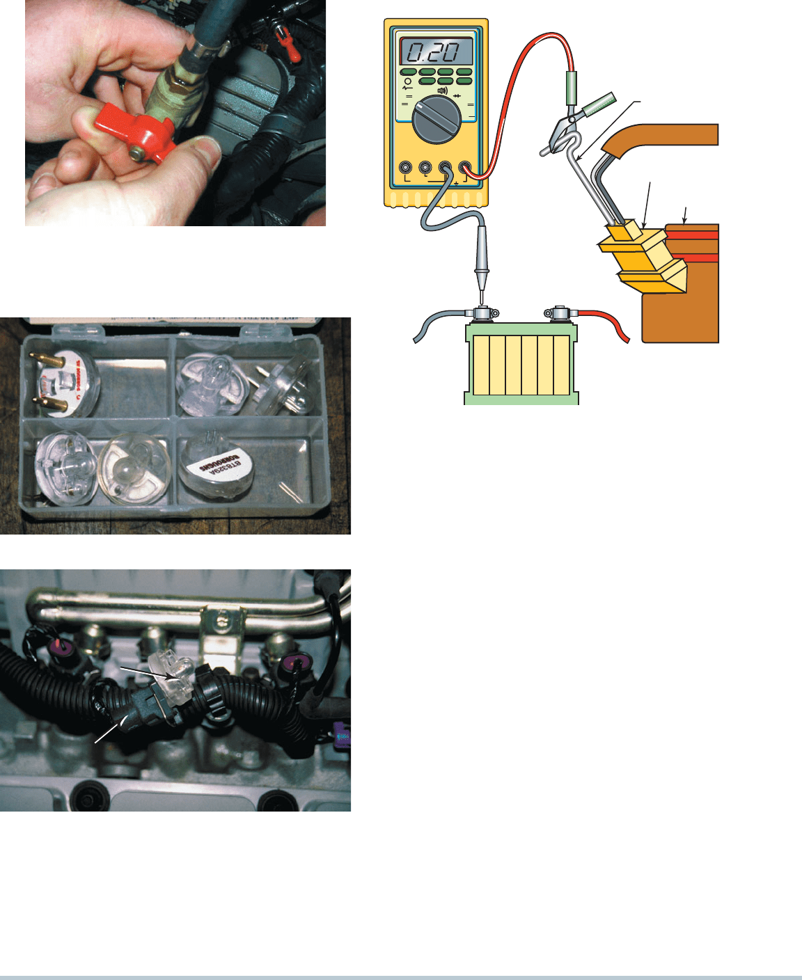
A noid light is designed to electrically replace the injector
in the circuit and to flash if the injector circuit is working cor-
rectly.
SEE FIGURE 23–9. To use a noid light, disconnect the
290 CHAPTER 23
FIGURE 23–8 Shutoff valves must be used on vehicles
equipped with plastic fuel lines to isolate the cause of a
pressure drop in the fuel system.
mV
V
–V
RPM
OFF
Ω
mA
A
mA
A
A mA COM
VΩ-M
RPM
VOLTS DC
BATTERY
POSITIVE
PROBE
HOT SIDE
OF INJECTOR
T-PIN
INJECTOR
CONNECTOR
INJECTOR
FIGURE 23–10 Use a DMM set to read DC volts to check
the voltage drop of the positive circuit to the fuel injector.
A reading of 0.5 volt or less is generally considered to be
acceptable.
(a)
(b)
NOID LIGHT
INJECTOR
CONNECTOR
FIGURE 23–9 (a) Noid lights are usually purchased as an as-
sortment so that one is available for any type or size of injector
wiring connector. (b) The connector is unplugged from the
injector, and a noid light is plugged into the injector connector.
The noid light should flash when the engine is being cranked
if the power circuit and the pulsing to ground by the computer
are functioning okay.
electrical connector at the fuel injector and plug the noid light
into the injector harness connections. Crank or start the engine.
The noid light should flash regularly.
NOTE: The term noid is simply an abbreviation of the
word solenoid. Injectors use a movable iron core and are
therefore solenoids. Therefore, a noid light is a replace-
ment for the solenoid (injector).
Possible noid light problems and causes include the
following:
1. The light is off and does not flash. The problem is an
open circuit in either the power side or the ground side (or
both) of the injector circuit.
2. The noid light flashes dimly. A dim noid light indicates
excessive resistance or low voltage available to the injec-
tor. Both the power and the ground side must be checked.
3. The noid light is on and does not flash. If the noid light is
on, then both a power and a ground are present. Because
the light does not flash (blink) when the engine is being
cranked or started, a short-to-ground fault exists either
in the computer itself or in the wiring between the injector
and the computer.
CAUTION: A noid lamp must be used with caution. The
computer may show a good noid light operation and
have low supply voltage.
SEE FIGURE 23–10.