Halderman J.D., Linder J. Automotive Fuel and Emissions Control Systems
Подождите немного. Документ загружается.

EVAPORATIVE EMISSION CONTROL SYSTEMS 321
PUMP SPEED
SENSOR
CONTROL
VALVE
VACUUM
SOURCE
DIAPHRAGM
SPRING
PRESSURE OUT
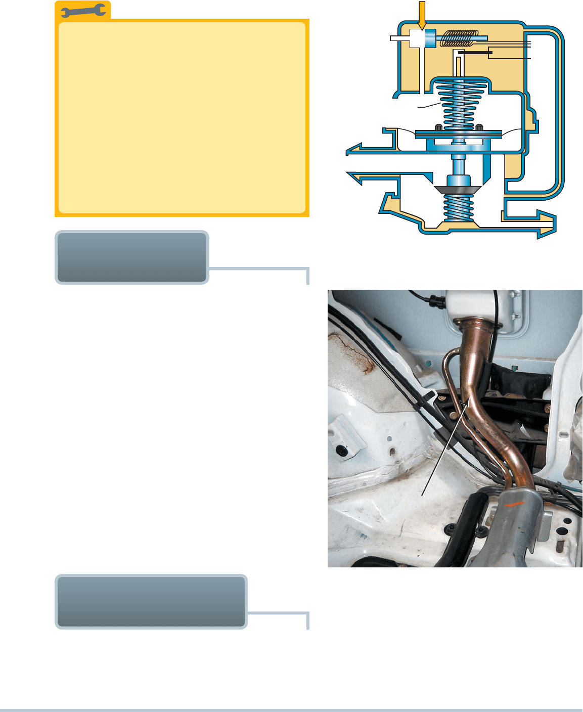
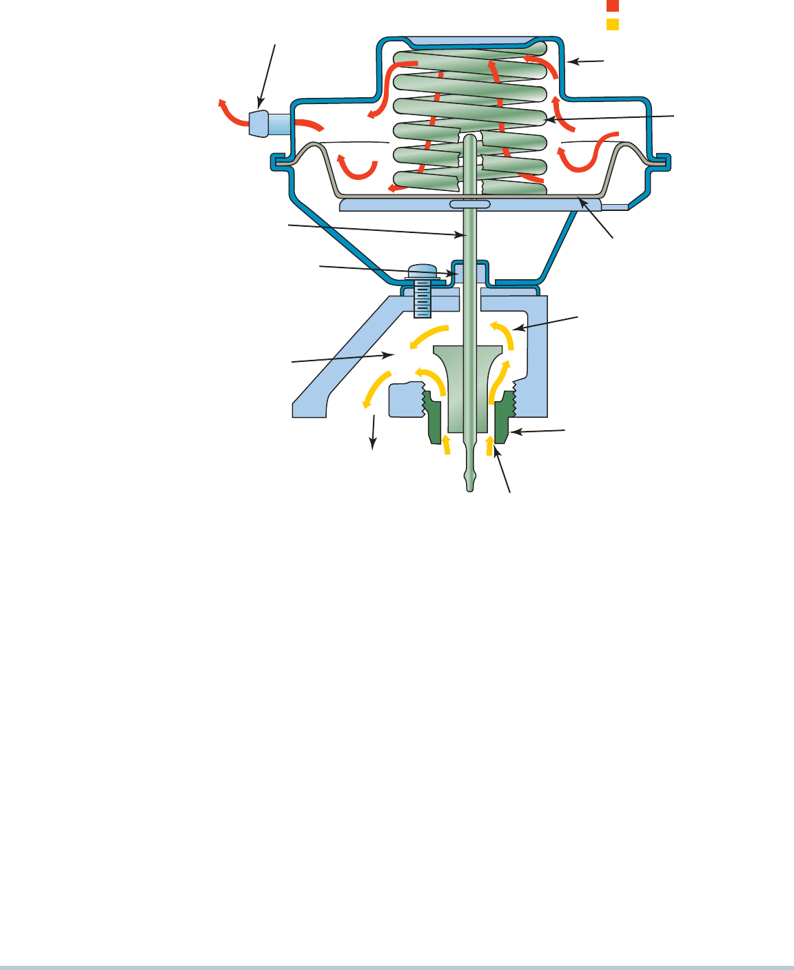
FIGURE 25–6 A leak detection pump (LDP) used on some
Chrysler and other vehicles to pressurize (slightly) the fuel
system to check for leaks.
Problems after Refueling? Check the Purge Valve
The purge valve is normally closed and open only
when the PCM is commanding the system to purge.
If the purge solenoid were to become stuck in the
open position, gasoline fumes would be allowed to
flow directly from the gas tank to the intake manifold.
When refueling, this would result in a lot of fumes
being forced into the intake manifold and as a result
cause a hard-to-start condition after refueling. This
would also result in a rich exhaust and likely black
exhaust when first starting the engine after refueling.
While the purge solenoid is usually located under the
hood of most vehicles and is less subject to rust and
corrosion as with the vent valve, it can still fail.
TECH TIP
LEAK DETECTION
PUMP SYSTEM
PURPOSE AND FUNCTION Many vehicles use a vacuum
operated leak detection pump (LDP) as part of the evapora-
tive control system diagnosis equipment.
SEE FIGURE 25–6 .
OPERATION The system works to test for leaks as follows:
The purge solenoid is normally closed.
The vent valve in the LDP is normally open. Filtered fresh
air is drawn through the LDP to the canister.
The LDP uses a spring attached to a diaphragm to apply
pressure (7.5 in. H
2
O) to the fuel tank.
The PCM monitors the LDP switch that is triggered if the
pressure drops in the fuel tank.
The time between LDP solenoid off and LDP switch close
is called the pump period. This time period is inversely
proportional to the size of the leak. The shorter the pump
period, the larger the leak. The longer the pump period,
the smaller the leak.
EVAP large leak (greater than 0.080 in.): less than 0.9 second
EVAP medium leak (0.040 to 0.080 in.): 0.9 to 1.2 seconds
EVAP small leak (0.020 to 0.040 in.): 1.2 to 6 seconds
ONBOARD REFUELING
VAPOR RECOVERY
PURPOSE AND FUNCTION The onboard refueling
vapor recovery (ORVR) system was first introduced on some
1998 vehicles. Previously designed EVAP systems allowed fuel
vapor to escape to the atmosphere during refueling.
RESTRICTED (NARROWED)
FUEL FILLER TUBE
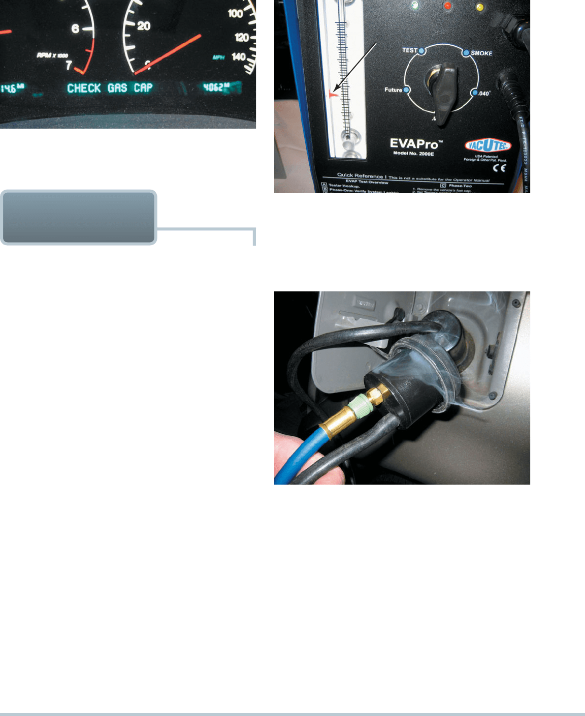
FIGURE 25–7 A restricted fuel fill pipe shown on vehicle with
the interior removed.
OPERATION The primary feature of most ORVR systems
is the restricted tank filler tube, which is about 1 inch (25 mm)
in diameter. This reduced size filler tube creates an aspiration
effect, which tends to draw outside air into the filler tube. During
refueling, the fuel tank is vented to the charcoal canister, which
captures the gas fumes, and with air flowing into the filler tube,
no vapors can escape to the atmosphere.
SEE FIGURE 25–7 .
322 CHAPTER 25
A leak will also cause a gas smell, which would be most
noticeable if the vehicle were parked in an enclosed garage. The
first step is to determine if there is a leak in the system by setting
the EVAP tester to rate the system for either a 0.040-inch-or a
0.020-inch-hole-size leak.
SEE FIGURE 25–9 .
After it has been determined that a leak exists and it is
larger than specified, one of two methods can be used to check
for leaks in the evaporative system:
Smoke machine testing. The most efficient method of
leak detection is to introduce smoke under low pressure
from a machine specifically designed for this purpose.
SEE FIGURE 25–10 .
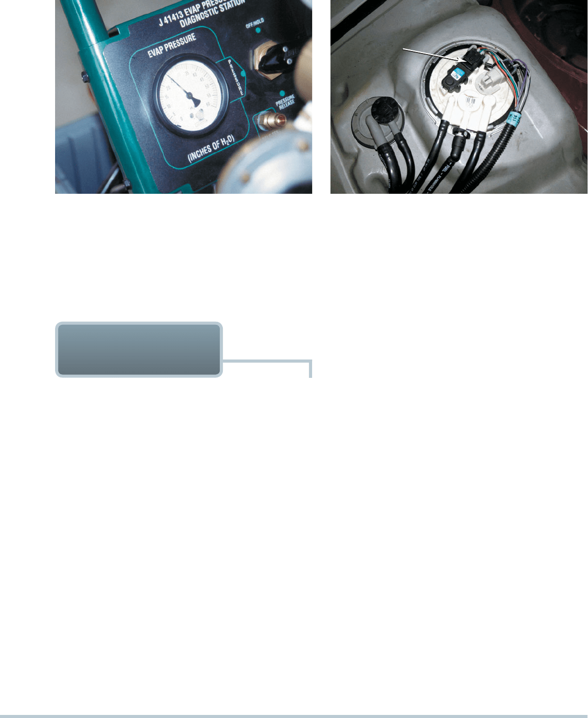
FIGURE 25–8 Some vehicles will display a message if an
evaporative control system leak is detected that could be the
result of a loose gas cap.
RED ARROW SET
TO 0.020 INCH
FIGURE 25–9 To test for a leak, this tester was set to the
0.020-inch hole and turned on. The ball rose in the scale on
the left, and the red arrow was moved to that location. If when
testing the system for leaks the ball rises higher than the arrow,
then the leak is larger than 0.02 inch. If the ball does not rise to
the level of the arrow, the leak is smaller than 0.020 inch.
FIGURE 25–10 This unit is applying smoke to the fuel tank
through an adapter, and the leak was easily found to be the
gas cap seal.
DIAGNOSING THE
EVAP SYSTEM
SYMPTOMS Before vehicle emissions testing began in many
parts of the country, little service work was done on the evapora-
tive emission system. Common engine performance problems
that can be caused by a fault in this system include the following:
Poor fuel economy. A leak in a vacuum-valve diaphragm
can result in engine vacuum drawing in a constant flow of
gasoline vapors from the fuel tank. This usually results in
a drop in fuel economy of 2 to 4 miles per gallon (mpg).
Use a hand-operated vacuum pump to check that the
vacuum diaphragm can hold vacuum.
Poor performance. A vacuum leak in the system can
cause the engine to run rough. Age, heat, and time all
contribute to the deterioration of rubber hoses.
STATE EVAP TESTS Enhanced exhaust emissions (I/M-
240) testing tests the evaporative emission system. A leak in the
system is tested by pressurizing the entire fuel system to a level
below 1 PSI (about 14 in. H
2
O). The system is typically pressur-
ized with nitrogen, a nonflammable gas that makes up 78% of
our atmosphere. The pressure in the system is then shut off and
the pressure monitored. If the pressure drops below a set stan-
dard, then the vehicle fails the test. This test determines if there
is a leak in the system.
HINT: To help pass the evaporative section of an en-
hanced emissions test, arrive at the test site with less
than a half tank of fuel. This means that the rest of the
volume of the fuel tank is filled with air. It takes longer
for the pressure to drop from a small leak when the vol-
ume of the air is greater compared to when the tank is
full and the volume of air remaining in the tank is small.
LOCATING LEAKS IN THE SYSTEM Leaks in the
evaporative emission control system will cause the malfunction
check gas cap indication lamp to light on some vehicles.
SEE
FIGURE 25–8 .
EVAPORATIVE EMISSION CONTROL SYSTEMS 323
Nitrogen gas pressurization. This method uses nitrogen
gas under a very low pressure (lower than 1 PSI) in the
fuel system. The service technician then listens for the
escaping air, using amplified headphones.
SEE
FIGURE 25–11 .
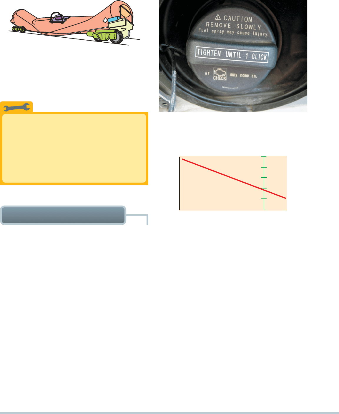
FIGURE 25–11 An emission tester that uses nitrogen to
pressurize the fuel system.
FUEL TANK
PRESSURE
(FTP) SENSOR
FIGURE 25–12 The fuel tank pressure sensor (black unit with
three wires) looks like a MAP sensor and is usually located on
top of the fuel pump module (white unit).
EVAPORATIVE
SYSTEM MONITOR
OBD-II REQUIREMENTS OBD-II computer programs not
only detect faults but also periodically test various systems
and alert the driver before emissions-related components are
harmed by system faults:
Serious faults cause a blinking malfunction indicator lamp
(MIL) or even an engine shutdown.
Less serious faults may simply store a code but not illu-
minate the MIL.
The OBD-II requirements did not affect fuel system design.
However, one new component, a fuel evaporative canister purge
line pressure sensor, was added for monitoring purge line pres-
sure during tests. The OBD-II requirements state that vehicle fuel
systems are to be routinely tested while under way by the PCM.
All OBD-II vehicles perform a canister purge system pres-
sure test, as commanded by the PCM. While the vehicle is being
driven, the vapor line between the canister and the purge valve
is monitored for pressure changes:
When the canister purge solenoid is open, the line should
be under a vacuum since vapors must be drawn from the
canister into the intake system. However, when the purge
solenoid is closed, there should be no vacuum in the line.
The pressure sensor detects if a vacuum is present, and
the information is compared to the command given to the
solenoid.
If, during the canister purge cycle, no vacuum exists in
the canister purge line, a code is set indicating a possible
fault, which could be caused by an inoperative or clogged
solenoid or a blocked or leaking canister purge fuel line.
Likewise, if vacuum exists when no command for purge is
given, a stuck solenoid is evident, and a code is set. The
EVAP system monitor tests for purge volume and leaks.
A typical EVAP monitor first closes off the system to at-
mospheric pressure and opens the purge valve during cruise
operation. A fuel tank pressure (FTP) sensor then monitors
the rate with which vacuum increases in the system. The moni-
tor uses this information to determine the purge volume flow
rate. To test for leaks, the EVAP monitor closes the purge valve,
creating a completely closed system. The fuel tank pressure
sensor then monitors the leak-down rate. If the rate exceeds
PCM-stored values, a leak greater than or equal to the OBD-II
standard of 0.04 inch (1 mm) or 0.02 inch (0.5 mm) exists. After
two consecutive failed trips testing either purge volume or the
presence of a leak, the PCM lights the MIL and sets a DTC.
The fuel tank pressure sensor is similar to a MAP sensor,
and instead of monitoring intake manifold absolute pressure, it
is used to monitor fuel tank pressure.
SEE FIGURE 25–12 .
ENGINE-OFF NATURAL VACUUM System integrity
(leakage) can also be checked after the engine is shut off.
The premise is that a warm evaporative system will cool
down after the engine is shut off and the vehicle is stable.
A slight vacuum will be created in the gas tank during this
cool-down period. If a specific level of vacuum is reached
and maintained, the system is said to have integrity (no
leakage). Actually, the vacuum is created after a period of
time because the vapor pressure tends to increase after the
engine is shut off and gradually decreases over time. The
PCM monitors the pressure rise and decrease over time and
triggers a diagnostic trouble code (DTC) if the pressure indi-
cates a leak in the system.
SEE FIGURE 25–13 .
324 CHAPTER 25
0-4-8-12-16 4
FUEL TANK PRESSURE SENSOR
VOLTAGE VS. INCHES OF WATER
VOLTAGE
DIFFERENTIAL PRESSURE INCHES (H2O)
1V
2V
3V
4V
5V
FIGURE 25–15 To easily check the fuel tank pressure sensor,
remove the cap, and the sensor should read about 1.7 volts.
FIGURE 25–13 A tank car was cleaned using steam, and
then both the bottom drain and the top vent were closed. The
next day, the tank had collapsed because of the air pressure
difference when the inside cooled. The higher outside air pres-
sure caused the tank to collapse.
FIGURE 25–14 This Toyota cap warns that the check engine
light will come on if not tightened until one click.
Always Tighten the Cap Correctly
Many diagnostic trouble codes (DTCs) are set
because the gas cap has not been properly installed.
To be sure that a screw-type gas cap is properly
sealed, tighten it until you hear three clicks. The
clicking is a ratchet device, and the clicking does not
harm the cap. Therefore, if a P0440 or similar DTC is
set, check the cap.
SEE FIGURE 25–14 .
TECH TIP
The PCM will run the EVAP monitor when the following enable
criteria are met:
Barometric pressure (BARO) greater than 70 kPa
(20.7 in. Hg or 10.2 PSI)
Intake air temperature (IAT) between 39°F and 86°F
(4°C to 30°C) at engine start-up
Engine coolant temperature (ECT) between 39°F and
86°F (4°C to 30°C) at engine start-up
ECT and IAT within 3°F of each other at engine start-up
Fuel level within 15% to 85%
Throttle position (TP) sensor between 9% and 35%
A typical EVAP monitor first closes off the system to atmo-
spheric pressure and opens the purge valve during cruise opera-
tion. A fuel tank pressure (FTP) sensor then monitors the rate with
which vacuum increases in the system.
SEE FIGURE 25–15 .
The monitor uses this information to determine the purge
volume flow rate. To test for leaks, the EVAP monitor closes
the purge valve, creating a completely closed system. The
fuel tank pressure sensor then monitors the leak-down rate.
If the rate exceeds PCM-stored values, a leak greater than or
equal to the OBD-II standard of 0.04 inch (1 mm) or 0.02 inch
(0.5mm) exists.
TYPICAL EVAP MONITOR
RUNNING THE EVAP MONITOR Four tests are per-
formed during a typical EVAP monitor. A DTC is assigned to
each test:
1. Weak vacuum test (P0440—large leak). This test identi-
fies gross leaks. During the monitor, the vent solenoid is
closed, and the purge solenoid is duty cycled. The fuel
tank pressure (FTP) should indicate a vacuum of approxi-
mately 6 to 10 in. H
2
O.
2. No flow during purging (P0441—no flow during purg-
ing). This test uses the fuel tank pressure (FTP) sensor
todetermine that there was no change in fuel tank pres-
sure during purging. This fault could be due to a defective
purge valve or a gross leak caused by faults such as a
defective or missing gas cap.
3. Small leak test (P0442—small leak). After the large leak
test passes, the PCM checks for a small leak by keeping
the vent solenoid closed and closing the purge solenoid.
The system is now sealed. The PCM measures the change
in FTP voltage over time.
EVAPORATIVE EMISSION CONTROL SYSTEMS 325
4. Excess vacuum test (P0446). This test checks for vent
path restrictions. With the vent solenoid open and purge
commanded, the PCM should not see excessive vacuum
in the EVAP system. Typical EVAP system vacuum with the
vent solenoid open is about 5 to 6 in. H
2
O.
FIGURE 25–16 The fuel level must be above 15% and below
85% before the EVAP monitor will run on most vehicles.
Diagnostic
Trouble Code Description Possible Causes
P0440 Evaporative
system fault
• Loose gas cap
• Defective EVAP vent
• Cracked charcoal
canister
• EVAP vent or purge
vapor line problems
P0442 Small leak
detected
• Loose gas cap
• Defective EVAP vent
or purge solenoid
• EVAP vent or purge
line problems
P0446 EVAP canister
vent blocked
• EVAP vent or purge
solenoid electrical
problems
• Restricted EVAP
canister vent line
EVAP SYSTEM-RELATED
DIAGNOSTIC TROUBLE
CODES
Keep the Fuel Tank Properly Filled
Most evaporative system monitors will not run
unless the fuel level is between 15% and 85%. In
other words, if a driver always runs with close to an
empty tank or always tries to keep the tank full, the
EVAP monitor may not run.
SEE FIGURE 25–16 .
TECH TIP
4. A typical EVAP system uses a canister purge valve, which
is normally closed, and a canister vent valve, which is nor-
mally open.
5 . OBD-II regulation requires that the evaporative emission
control system be checked for leakage and proper purge
flow rates.
6. External leaks can best be located by pressurizing the fuel
system with low-pressure smoke.
1. The purpose of the evaporative emission control (EVAP)
system is to reduce the release of volatile organic com-
pounds (VOCs) into the atmosphere.
2. A carbon (charcoal) canister is used to trap and hold gaso-
line vapors until they can be purged and run into the engine
to be burned.
3. Pressures inside the EVAP system are low and are meas-
ured in inches of water (1 PSI 28 in. H
2
O).
SUMMARY

326 CHAPTER 25
4. Why is the vent valve subject to rust and corrosion?
5. What are the parameters (enable criteria) that must be met
for the evaporative system monitor to run?
1. What components are used in a typical evaporative emis-
sion control system?
2. How does the computer control the purging of the vapor
canister?
3. What is the difference between an enhanced and a nonen-
hanced evaporative control system?
REVIEW QUESTIONS
7. Which EVAP valve is subject to rust and corrosion more
than all of the others?
a. Purge valve
b. Vacuum control valve
c. Vent valve
d. Roll over check valve
8. Before an evaporative emission monitor will run, the fuel
level must be where?
a. At least 75% full
b. Over 25%
c. Between 15% and 85%
d. The level of the fuel in the tank is not needed to run
the monitor test
9. Technician A says that low-pressure smoke installed in
the fuel system can be used to check for leaks. Technician
B says that nitrogen under low pressure can be installed
in the fuel system to check for leaks. Which technician is
correct?
a. Technician A only
b. Technician B only
c. Both Technicians A and B
d. Neither Technician A nor B
10. A small leak is detected by the evaporative emission con-
trol system monitor that could be caused by a loose gas
cap. Which DTC will likely be set?
a. P0440
b. P0442
c. P0446
d. P0440, P0441, or P0442
1. What is the substance used in a vapor canister to absorb
volatile organic compounds?
a. Desiccant c. Pleated paper
b.
Organic absorber
d. Carbon
2. Which valve(s) is (are) normally closed?
a. Canister purge valve
b. Canister vent valve
c. Both canister purge and canister vent valves
d. Neither canister purge nor canister vent valve
3. All of the following can increase the pressure in the evapo-
rative emission control system except ______________ .
a. Fuel temperature
b. Returned fuel from the fuel-injection system
c. Inlet fuel to the fuel pump
d. Volatility of the fuel
4. Evaporative emission control systems operate on low
pressure measured in inches of water (in. H
2
O). One PSI is
equal to how many inches of water?
a. 1 c. 18
b. 10 d. 28
5. Inadequate purge flow rate will trigger which DTC?
a. P0440 c. P0300
b. P0446 d. P0440 or P0446
6. Two technicians are discussing a state emission test.
Technician A says that a vent valve that is not able to close
can cause the system to fail the on-board test. Technician
B says that a leaking gas cap can cause a failure of the
EVAP test. Which technician is correct?
a. Technician A only
b. Technician B only
c. Both Technicians A and B
d. Neither Technician A nor B
CHAPTER QUIZ
EXHAUST GAS RECIRCULATION SYSTEMS 327
chapter
EXHAUST GAS
RECIRCULATION
SYSTEMS
26
OBJECTIVES: After studying Chapter 26 , the reader should be able to: • Prepare for the ASE Engine Performance (A8)
certification test content area “D” (Emission Control Systems). • Describe the purpose and function of the exhaust gas
recirculation system. • Discuss how the exhaust gas recirculation system is tested under OBD-II regulations. • Explain methods
for diagnosing and testing for faults in the exhaust gas recirculation system.
KEY TERMS: Delta pressure feedback EGR (DPFE) sensor 331 • Detonation 328 • Digital EGR valve 330 • EGR valve
position (EVP) sensor 329 • Electronic vacuum regulator valve (EVRV) 332 • Exhaust gas recirculation (EGR) 327 • Inert 327
• Linear EGR valve 330 • Nitrogen oxides (NO
x
) 327 • Pressure feedback EGR (PFE) sensor 329
EXHAUST GAS
RECIRCULATION SYSTEMS
INTRODUCTION Exhaust gas recirculation (EGR) is an
emission control system that lowers the amount of nitrogen
oxides (NO
x
) formed during combustion. In the presence of
sunlight, NO
x
reacts with hydrocarbons in the atmosphere to
form ozone (O
3
) or photochemical smog, an air pollutant.
NO
X
FORMATION Nitrogen (N
2
) and oxygen (O
2
) molecules
are separated into individual atoms of nitrogen and oxygen
during the combustion process. These molecules then bond
to form NO
x
(NO, NO
2
). When combustion flame front tem-
peratures exceed 2,500°F (1,370°C), NO
x
is formed inside the
cylinder, which is then discharged into the atmosphere from the
tailpipe.
SEE FIGURE 26–1 .
CONTROLLING NO
X
To handle the NO
x
generated above
2,500°F (1,370°C), the most efficient method to meet NO
x
emis-
sions without significantly affecting engine performance, fuel
economy, and other exhaust emissions is to use exhaust gas
recirculation (EGR). The EGR system routes small quantities,
usually between 6% and 10%, of exhaust gas into the intake
manifold.
Here, the exhaust gas mixes with and takes the place of
some intake charge. This leaves less room for the intake charge
to enter the combustion chamber. The recirculated exhaust gas
is inert (chemically inactive) and does not enter into the com-
bustion process. The result is a lower peak combustion tem-
perature. When the combustion temperature is lowered, the
production of oxides of nitrogen is reduced.
FIGURE 26–1 Nitrogen oxides (NO
x
) create a red-brown
haze that often hangs over major cities.
The EGR system has some means of interconnecting the
exhaust and intake manifolds.
SEE FIGURE 26–2 .
The EGR valve controls the flow of exhaust gases through
the interconnecting passages:
On V-type engines, the intake manifold crossover is used
as a source of exhaust gas for the EGR system. A cast
passage connects the exhaust crossover to the EGR
valve. The exhaust gas is sent from the EGR valve to
openings in the manifold.
On inline-type engines, an external tube is generally used
to carry exhaust gas to the EGR valve. This tube is often
designed to be long so that the exhaust gas is cooled be-
fore it enters the EGR valve.
328 CHAPTER 26
EGR SYSTEM OPERATION Since small amounts of
exhaust are all that is needed to lower peak combustion tem-
peratures, the orifice through which the exhaust passes is small.
EGR is usually not required during the following conditions
because the combustion temperatures are low:
During idle speed
When the engine is cold
At wide-open throttle (WOT) (Not allowing EGR allows the
engine to provide extra power when demanded. While the
NO
x
formation is high during these times, the overall effect of
not using EGR during WOT conditions is minor.)
The level of NO
x
emission changes according to engine
speed, temperature, and load. Many systems use a cooler to
reduce the temperature of the exhaust gases before they enter
the intake manifold. The cooler the exhaust gases, the more ef-
fective they are at reducing the formation of NO
x
.
EGR BENEFITS In addition to lowering NO
x
levels, the EGR
system also helps control detonation. Detonation, also called
spark knock or ping, occurs when high pressure and heat cause
the air-fuel mixture to ignite. This uncontrolled combustion can
severely damage the engine.
Using the EGR system allows for greater ignition timing ad-
vance and for the advance to occur sooner without detonation
problems, which increases power and efficiency.
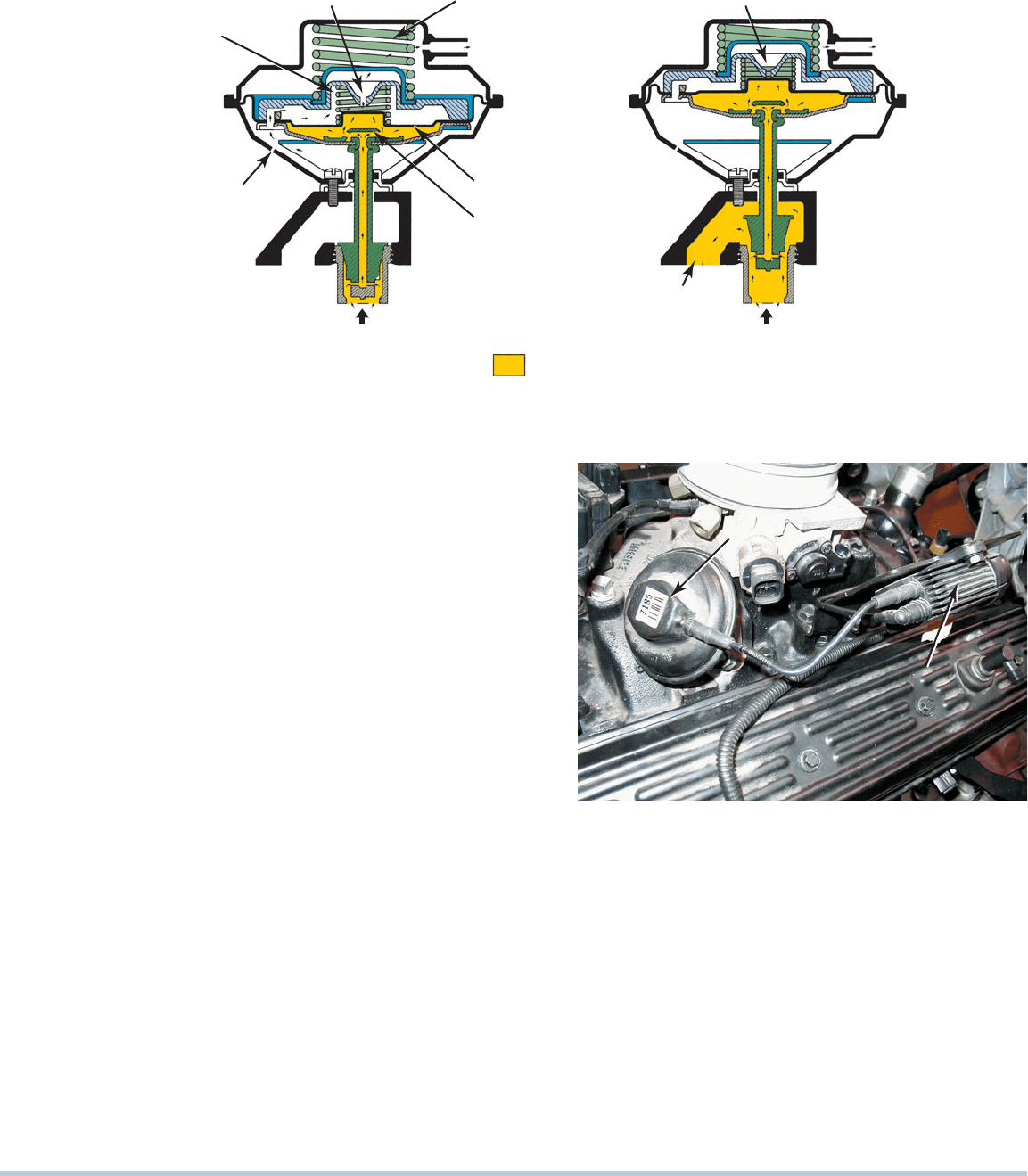
POSITIVE AND NEGATIVE BACK PRESSURE EGR
VALVES Some vacuum-operated EGR valves used on older
engines are designed with a small valve inside that bleeds off
any applied vacuum and prevents the valve from opening:
Positive back pressure EGR valves. These EGR valves
require a positive back pressure in the exhaust system.
At low engine speeds and light engine loads, the EGR
system is not needed, and the back pressure in it is also
low. Without enough back pressure, the EGR valve does
not open even though vacuum may be present at the
EGR valve.
SEE FIGURE 26–3 .
Negative back pressure EGR valves. On each
exhaust stroke, the engine emits an exhaust “pulse.”
Each pulse represents a positive pressure. Behind each
pulse is a small area of low pressure. Some EGR valves
react to this low-pressure area by closing a small inter-
nal valve, which allows the EGR valve to be opened by
vacuum.
DIAPHRAGM
COVER
SPRING
ACTUATING
DIAPHRAGM
VALVE ½ OPEN
VALVE SEAT
VALVE
CHAMBER
TO INTAKE
MANIFOLD
VALVE SHAFT
SEAL
CONTROLLED VACUUM
CONNECTION
EXHAUST GAS
PORT INLET
VACUUM
EXHAUST
FIGURE 26–2 When the EGR
valve opens, the exhaust gases
flow through the valve and into
passages in the intake manifold.
EXHAUST GAS RECIRCULATION SYSTEMS 329
The following conditions must occur before a back
pressure-type vacuum-controlled EGR will operate:
1. Vacuum must be applied to the EGR valve itself. The
vacuum source can be ported vacuum (above the throttle
plate) or manifold vacuum (below the throttle plate) and by
the computer through a solenoid valve.
2. Exhaust back pressure must be present to close an inter-
nal valve inside the EGR to allow the vacuum to move the
diaphragm.
NOTE: Installing a high-performance exhaust system
could prevent a back pressure vacuum-operated EGR
valve from opening. If this is occurs, excessive combus-
tion chamber pressure may lead to severe spark knock,
piston damage, or a blown head gasket.
COMPUTER-CONTROLLED EGR SYSTEMS Most
vehicles today use the Powertrain Control Module (PCM) to
operate the EGR system. Many PCM-controlled EGR systems
have one or more solenoids controlling the EGR vacuum. The
PCM controls a solenoid to shut off vacuum to the EGR valve
at cold engine temperatures, idle speed, and WOT operation. If
two solenoids are used, one acts as an off/on control of supply
vacuum, while the second solenoid vents vacuum when EGR
flow is not desired or needs to be reduced. The second solenoid
is used to control a vacuum air bleed, allowing atmospheric
pressure in to modulate EGR flow according to vehicle operat-
ing conditions.
SEE FIGURE 26–4 .
EGR VALVE POSITION SENSORS Most PCM vacuum-
operated EGR systems use a sensor to indicate EGR operation.
EXHAUST GASES
EXHAUST GAS
TO INTAKE MANIFOLD
HIGH
EXHAUST
BACK PRESSURE
TO VACUUM
SOURCE
SOURCE VACUUM
BLEED HOLE
CLOSED
AIRFLOW IN
LOW
EXHAUST
BACK PRESSURE
DEFLECTOR
DIAPHRAGM
TO VACUUM
SOURCE
VACUUM
CHAMBER
SOURCE VACUUM
BLEED HOLE
OPEN
CONTROL
VALVE
SPRING
VALVE
OPEN
POSITIVE BACK PRESSURE EGR VALVE OPERATION
VALVE
CLOSED
FIGURE 26–3 Back pressure in the exhaust system is used to close the control valve, allowing engine vacuum to open the EGR valve.
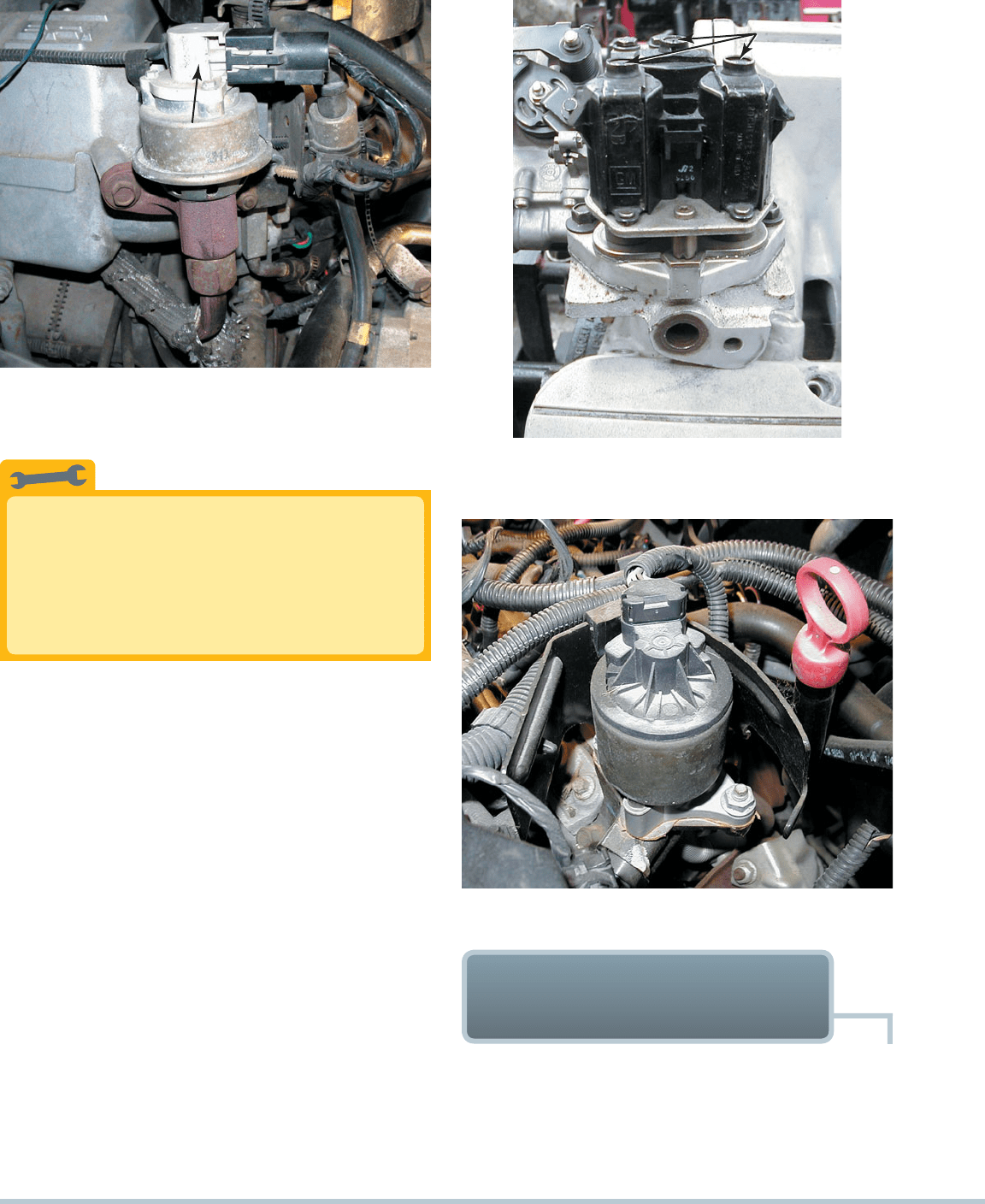
EGR VALVE
EGR CONTROL SOLENOID
FIGURE 26–4 Typical vacuum-operated EGR valve. The
operation of the valve is controlled by the PCM by pulsing the
EGR control solenoid on and off.
Onboard diagnostics generation II (OBD-II) EGR system monitors
require an EGR sensor to verify that the valve opened. A linear
potentiometer on the top of the EGR valve stem indicates valve
position to the PCM. This is called an EGR valve position (EVP)
sensor. Some later-model Ford EGR systems, however, use a
feedback signal provided by an EGR exhaust back pressure sen-
sor that converts the exhaust back pressure to a voltage signal.
This sensor is called a pressure feedback EGR (PFE) sensor.
On some EGR systems, the top of the valve contains a vac-
uum regulator and EGR pintle-position sensor in one assembly
330 CHAPTER 26
sealed inside a nonremovable plastic cover. The pintle-position
sensor provides a voltage output to the PCM, which increases
as the duty cycle increases, allowing the PCM to monitor valve
operation.
SEE FIGURE 26–5 .
DIGITAL EGR VALVES General Motors used a digital EGR
valve design on some engines. Unlike vacuum-operated EGR
valves, the digital EGR valve consists of three solenoids con-
trolled by the powertrain control module (PCM). Each solenoid
controls a different size orifice in the base—small, medium,
and large. The PCM controls the ground circuit of each of the
solenoids individually. It can produce any of seven different flow
rates, using the solenoids to open the three valves in different
combinations. The digital EGR valve offers precise control and
using a swivel pintle design helps prevent carbon deposit prob-
lems.
SEE FIGURE 26–6 .
LINEAR EGR Most General Motors and many other vehicles
use a linear EGR valve that contains a pulse-width modulated
solenoid to precisely regulate exhaust gas flow and a feedback
potentiometer that signals the PCM regarding the actual posi-
tion of the valve.
SEE FIGURES 26–7 AND 26–8 .
Find the Root Cause
Excessive back pressure, such as that caused by a
partially clogged exhaust system, could cause the
plastic sensors on the EGR valve to melt. Always
check for a restricted exhaust whenever replacing a
failed EGR valve sensor.
TECH TIP
EGR VALVE POSITION SENSOR
FIGURE 26–5 An EGR valve position sensor on top
of an EGR valve.
THREE EGR
SOLENOIDS
THREE EGR
SOLENOIDS
FIGURE 26–6 Digital EGR valve as used on some older
General Motors engines.
FIGURE 26–7 A General Motors linear EGR valve.
OBD-II EGR MONITORING
STRATEGIES
PURPOSE AND FUNCTION In 1996, the U.S. EPA began
requiring OBD-II systems in all passenger cars and most light-
duty trucks. These systems include emission system monitors
that alert the driver and the technician if an emission system is
malfunctioning. The OBD-II system performs this test by opening