Halderman J.D., Linder J. Automotive Fuel and Emissions Control Systems
Подождите немного. Документ загружается.

FUEL-INJECTION SYSTEM DIAGNOSIS AND SERVICE 291
COM
A
mA A
mV
V
V
mA
A
A
V
DIGITAL MULTIMETER
RECORD
MAX MIN
HZ
%
10
2
3 4 5
6
7
8
9
0
HZ
MAXMIN
15.20
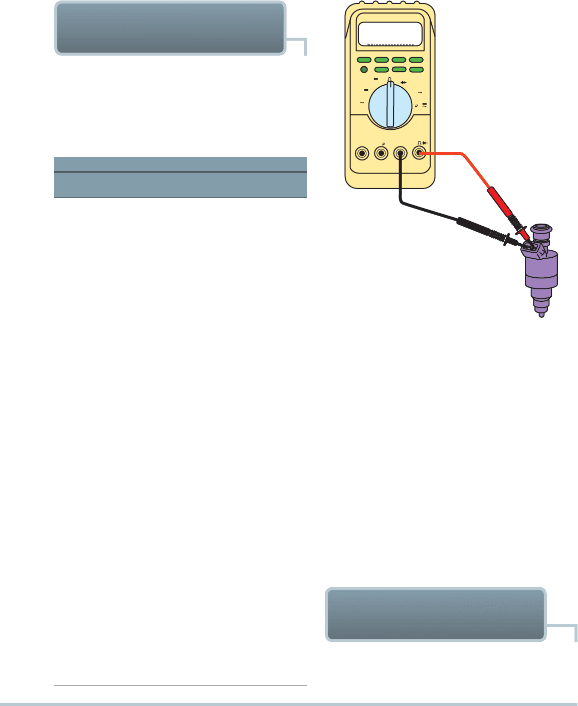
FIGURE 23–11 Connections and settings necessary
tomeasure fuel-injector resistance.
NOTE: Some engines require specific procedures to
gain access to the injectors. Always follow the manu-
facturer’s recommended procedures.
With an ohmmeter, measure the resistance across the in-
jector terminals. Be sure to use the low-ohms feature of the
digital ohmmeter to read in tenths (0.1) of an ohm.
SEE
FIGURES 23–11 AND 23–12. Check service information for
the resistance specification of the injectors. Measure the resis-
tance of all of the injectors. Replace any injector that does not
fall within the resistance range of the specification. The resis-
tance of the injectors should be measured twice—once when
the engine (and injectors) are cold and once after the engine
has reached normal operating temperature. If any injector mea-
sures close to specification, make certain that the terminals of
the injector are electrically sound and perform other tests to
confirm an injector problem before replacement.
CHECKING FUEL-INJECTOR
RESISTANCE
Each port fuel injector must deliver an equal amount of fuel, or
the engine will idle roughly or perform poorly.
The electrical balance test involves measuring the injector
coil-winding resistance. For best engine operation, all injectors
should have the same electrical resistance. To measure the re-
sistance, carefully release the locking feature of the connector
and remove the connector from the injector.
Injector Resistance Table
Manufacturer Injector Application
Resistance
Values
General Motors
Quad 4 1.95–2.15 Ω
CPI Vortec 4.3L 1.48–1.52 Ω
MFI Bosch Style Injector
(1985–1989) 2.8L
15.95–16.35 Ω
MFI Black Multec Injector
2.8L, 3.1L, 3.3L, 3.4L
11.8–12.6 Ω
MFI 3800 14.3–14.7 Ω
MFI 3.8L, 5.0L, 5.7L 15.8–16.6 Ω
MFI 5.7 LT5-ZR1 11.8–12.6 Ω
TBI 220 Series 2.8L, 3.1L,
4.3L, 5.0L, 5.7L, 7.4L
1.16–1.36 Ω
TBI 295 Series 4.3L,
6.0L, 7.0L
1.42–1.62 Ω
TBI 700 Series 2.0L,
2.2L, 2.5L
1.42–1.62 Ω
Chrysler Brand
MFI Early Years through
1992 (majority of)
2.4 Ω
MFI Later Years after
1992 (majority of)
14.5 Ω
TBI Low-Pressure
Systems (majority of)
1.3 Ω
TBI High-Pressure
Systems (majority of)
0.7 Ω
Ford
MFI (majority of) 15.0–18.0 Ω
TBI Low-Pressure 1.9L
(1987–1990)
1.0–2.0 Ω
TBI Low-Pressure 2.3L
(1985–1987)
1.0–2.0 Ω
TBI Low-Pressure 2.5L
(1986–1990)
1.0–2.0 Ω
TBI High-Pressure 3.8L
(1984–1987)
1.5–2.5 Ω
TBI High-Pressure 5.0L
(1981–1985)
1.5–3.5 Ω
MEASURING RESISTANCE
OF GROUPED INJECTORS
Many vehicles are equipped with a port fuel-injection system
that “fires” two or more injectors at a time. For example, a V-6
may group all three injectors on one bank to pulse on at the
292 CHAPTER 23
FIGURE 23–12 To measure fuel-injector resistance, a techni-
cian constructed a short wiring harness with a double banana
plug that fits into the V and COM terminals of the meter and
an injector connector at the other end. This setup makes
checking resistance of fuel injectors quick and easy.
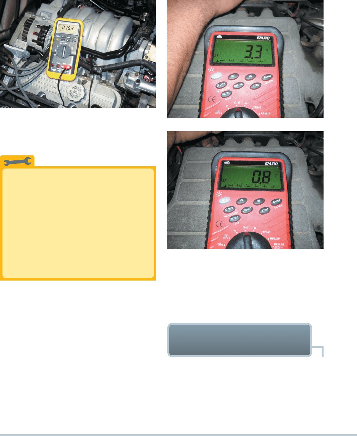
(a)
(b)
FIGURE 23–13 (a) The meter is connected to read one group
of three 12-ohm injectors. The result should be 4 ohms, and
this reading is a little low, indicating that at least one injector
is shorted (low resistance). (b) This meter is connected to the
other group of three injectors and indicates that most, if not
all three, injectors are shorted. The technician replaced all six
injectors, and the engine ran great.
same time. Then the other three injectors will be pulsed on. This
sequence alternates. To measure the resistance of these injec-
tors, it is often easiest to measure each group of three that is
wired in parallel. The resistance of three injectors wired in paral-
lel is one-third of the resistance of each individual injector. An
example follows:
Injector resistance = 12 ohms (Ω)
Three injectors in parallel = 4 ohms (Ω)
A V-6 has two groups of three injectors. Therefore, both
groups should measure the same resistance. If both groups
measure 4 ohms, then it is likely that all six injectors are okay.
However, if one group measures only 2.9 ohms and the other
group measures 4 ohms, then it is likely that one or more fuel
injectors are defective (shorted). This means that the technician
now has reasonable cause to remove the intake manifold to get
access to each injector for further testing.
SEE FIGURE 23–13.
Equal Resistance Test
All fuel injectors should measure the specified resist-
ance. However, the specification often indicates that
the temperature of the injectors be at room temperature
and of course will vary according to the temperature.
Rather than waiting for all of the injectors to achieve
room temperature, measure the resistance and check
that they are all within 0.4 ohm of each other. To
determine the difference, record the resistance of each
injector and then subtract the lowest resistance reading
from the highest resistance reading to get the differ-
ence. If more than 0.4 ohm, then further testing will be
needed to verify defective injector(s).
TECH TIP
MEASURING RESISTANCE
OF INDIVIDUAL INJECTORS
While there are many ways to check injectors, the first test is
to measure the resistance of the coil inside and compare it to
factory specifications.
SEE FIGURE 23–14. If the injectors
are not accessible, check service information for the location of
the electrical connector for the injectors. Unplug the connector
and measure the resistance of each injector at the injector side
of the connector. Use service information to determine the wire
colors for the power side and the pulse side of each injector.
FUEL-INJECTION SYSTEM DIAGNOSIS AND SERVICE 293
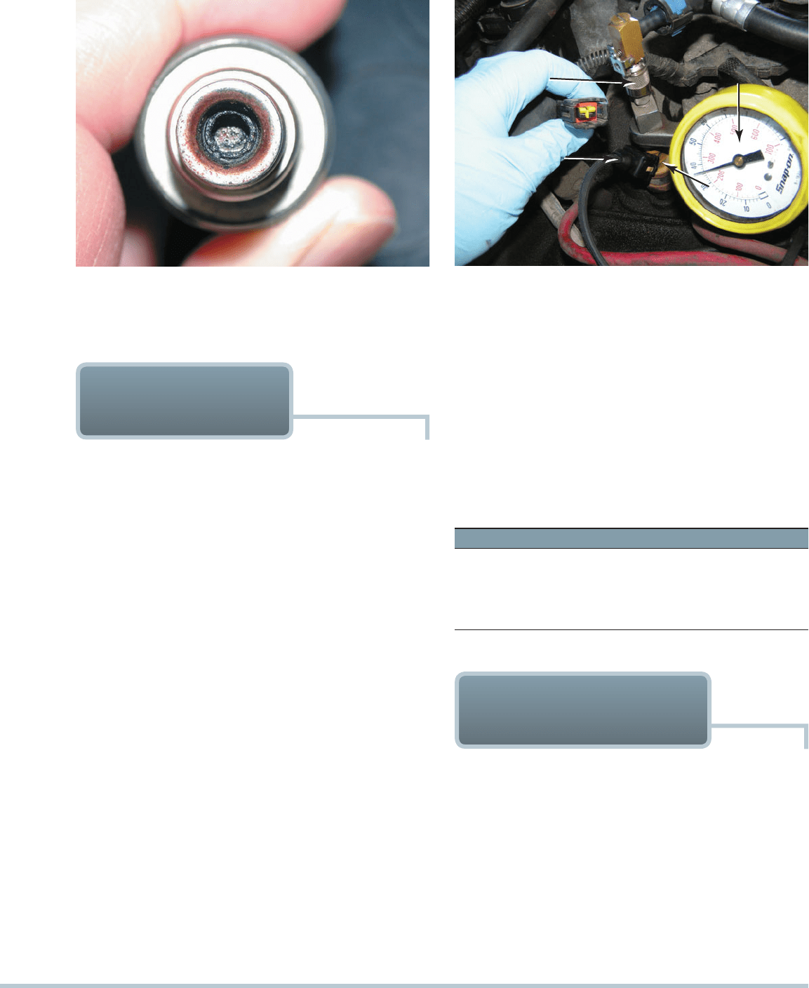
FIGURE 23–14 If an injector has the specified resistance,
this does not mean that it is okay. This injector had the speci-
fied resistance, yet it did not deliver the correct amount of fuel
because it was clogged.
SCHRADER
VALVE
TEST CONNECTOR
FROM PULSE UNIT
INJECTOR
FUEL-PRESSURE
GAUGE
FIGURE 23–15 Connect a fuel-pressure gauge to the fuel rail
at the Schrader valve.
PRESSURE-DROP
BALANCE TEST
The pressure balance test involves using an electrical timing
device to pulse the fuel injectors on for a given amount of time,
usually 500 ms, or 0.5 second, and observing the drop in pres-
sure that accompanies the pulse. If the fuel flow through each
injector is equal, the drop in pressure in the system will be equal.
Most manufacturers recommend that the pressures be within
about 1.5 PSI (10 kPa) of each other for satisfactory engine per-
formance. This test method not only tests the electrical function-
ing of the injector (for definite time and current pulse) but also
tests for mechanical defects that could affect fuel flow amounts.
The purpose of running this injector balance test is to deter-
mine which injector is restricted, inoperative, or delivering fuel differ-
ently than the other injectors. Replacing a complete set of injectors
can be expensive. The basic tools needed are the folowing:
Accurate pressure gauge with pressure relief
Injector pulser with time control
Necessary injector connection adapters
Safe receptacle for catching and disposing of any fuel
released
STEP 1 Attach the pressure gauge to the fuel delivery rail on
the supply side. Make sure the connections are safe
and leakproof.
STEP 2 Attach the injector pulser to the first injector to be
tested.
STEP 3 Turn the ignition key to the on position to prime the
fuel rail. Note the static fuel-pressure reading.
SEE
FIGURE 23–15.
STEP 4 Activate the pulser for the timed firing pulses.
STEP 5 Note and record the new static rail pressure after the
injector has been pulsed.
STEP 6 Reenergize the fuel pump and repeat this procedure
for all of the engine injectors.
STEP 7 Compare the two pressure readings and compute the
pressure drop for each injector. Compare the pressure
drops of the injectors to each other. Any variation in
pressure drops will indicate an uneven fuel delivery
rate between the injectors.
An example follows:
Injector 1 2 3 4 5 6
Initial pressure 40 40 40 40 40 40
Second pressure 30 30 35 30 20 30
Pressure drop 10 10 5 10 20 10
Possible problem OK OK Restriction OK Leak OK
INJECTOR VOLTAGE-
DROP TESTS
Another test of injectors involves pulsing the injector and mea-
suring the voltage drop across the windings as current is flow-
ing. A typical voltage-drop tester is shown in
FIGURE 23–16.
The tester, which is recommended for use by General Motors
Corporation, pulses the injector while a digital multimeter is
connected to the unit, which will display the voltage drop as the
current flows through the winding.
CAUTION: Do not test an injector using a pulse-type
tester more than one time without starting the engine to
help avoid a hydrostatic lock caused by the flow of fuel
into the cylinder during the pulse test.
294 CHAPTER 23
MENU
RECORD
SAVE
RECALL
AUTO
RANGE
AUTOMOTIVE SCOPMETER
0
5
10
15
20
25
-5
VEHICLE
DATA
PRADE
SINGLE
RANGE
HOLD
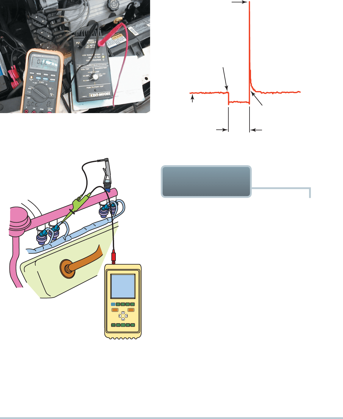
FIGURE 23–17 A digital storage oscilloscope can be easily
connected to an injector by carefully back probing the electrical
connector.
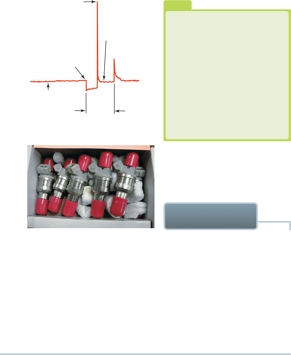
PEAK VOLTAGE CAUSED
BY THE COLLAPSE OF THE
INJECTOR COIL
DRIVER TRANSISTOR TURNS
ON, PULLING THE INJECTOR
PINTLE AWAY FROM ITS
SEAT, STARTING FUEL FLOW
BATTERY VOLTAGE
(SOURCE VOLTAGE
SUPPLIED TO INJECTOR)
DRIVER TRANSISTOR
TURNS OFF, ENDING
FUEL FLOW
INJECTOR
ON-TIME
FIGURE 23–18 The injector on-time is called the pulse
width. (Courtesy of Fluke Corporation)
FIGURE 23–16 An injector tester being used to check the volt-
age drop through the injector while the tester is sending current
through the injectors. This test is used to check the coil inside the
injector. This same tester can be used to check for equal pres-
sure drop of each injector by pulsing the injector on for 500 ms.
SCOPE-TESTING
FUEL INJECTORS
A scope (analog or digital storage) can be connected into each
injector circuit. There are three types of injector drive circuits,
and each type of circuit has its own characteristic pattern.
SEE FIGURE 23–17 for an example of how to connect a
scope to read a fuel-injector waveform.
SATURATED SWITCH TYPE In a saturated switch-
type injector-driven circuit, voltage (usually a full 12 volts)
is applied to the injector. The ground for the injector is pro-
vided by the vehicle computer. When the ground connection
is completed, current flows through the injector windings.
Because of the resistance and inductive reactance of the
coil itself, it requires a fraction of a second (about 3 ms, or
0.003second) for the coil to reach saturation, or maximum
current flow. Most saturated switch-type fuel injectors have
12 to 16 ohms of resistance. This resistance, as well as the
computer switching circuit, control and limit the current flow
through the injector. A voltage spike occurs when the com-
puter shuts off (opens the injector ground-side circuit) the
injectors.
SEE FIGURE 23–18.
PEAK-AND-HOLD TYPE A peak-and-hold type is typi-
cally used for TBI and some port low-resistance injectors. Full
battery voltage is applied to the injector, and the ground side is
controlled through the computer. The computer provides a high
initial current flow (about 4 amperes) to flow through the injector
windings to open the injector core. Then the computer reduces
the current to a lower level (about 1 ampere). The hold current
Record the highest voltage drop observed on the meter dis-
play during the test. Repeat the voltage-drop test for all of the injec-
tors. The voltage drop across each injector should be within 0.1 volt
of each other. If an injector has a higher-than-normal voltage drop,
the injector windings have higher-than-normal resistance.
FUEL-INJECTION SYSTEM DIAGNOSIS AND SERVICE 295
PEAK VOLTAGE CAUSED
BY THE COLLAPSE OF THE
INJECTOR COIL, WHEN
CURRENT IS REDUCED
DRIVER TRANSISTOR TURNS
ON, PULLING THE INJECTOR
PINTLE AWAY FROM ITS SEAT,
BEGINNING FUEL FLOW
CURRENT REDUCED
ENOUGH TO KEEP
HOLD-IN WINDING
ACTIVATED
INJECTOR
ON-TIME
BATTERY VOLTAGE
(SOURCE VOLTAGE
SUPPLIED TO INJECTOR)
FIGURE 23–19 A typical peak-and-hold fuel-injector wave-
form. Most fuel injectors that measure less than 6 ohms will
usually display a similar waveform.
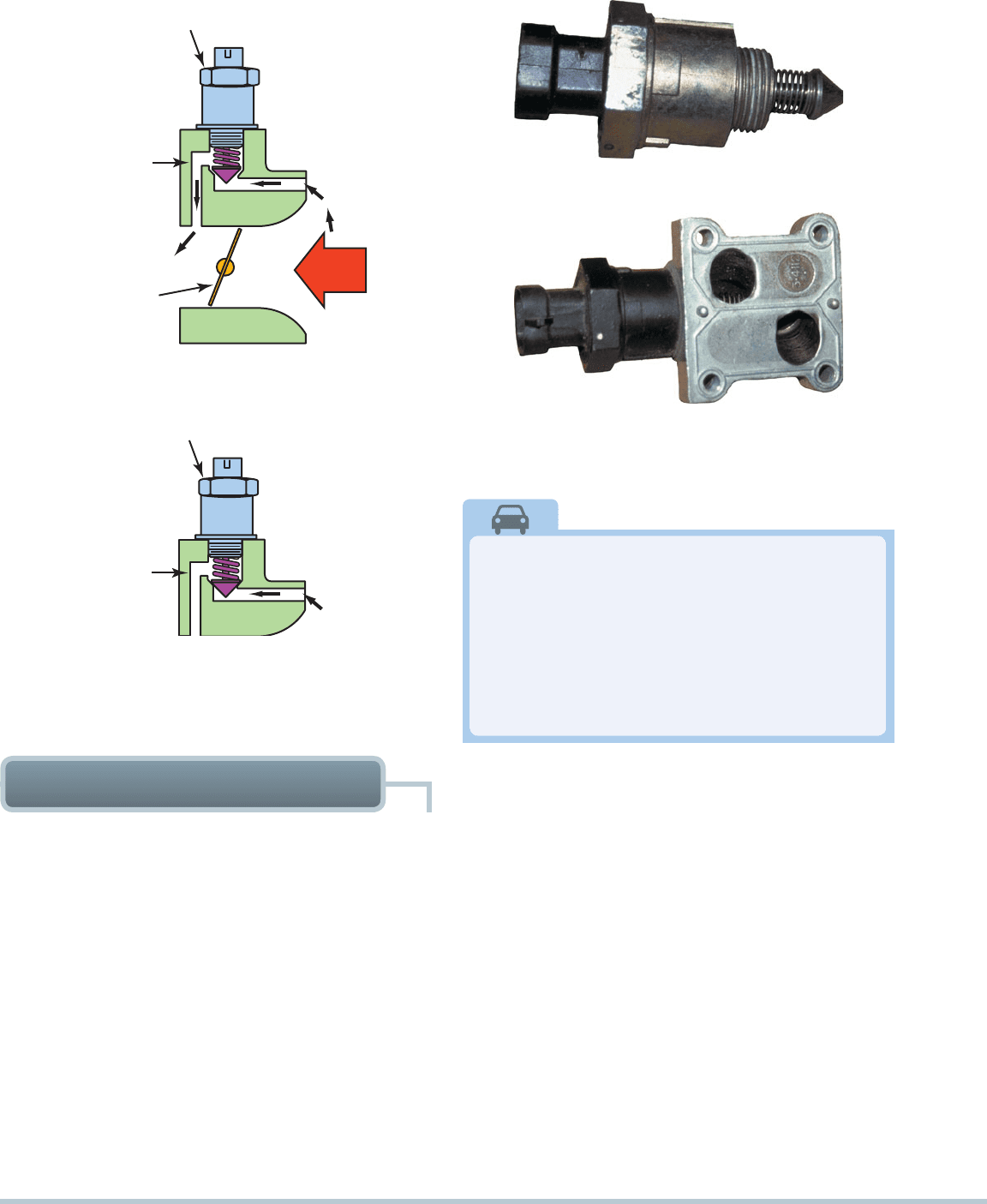
FIGURE 23–20 A set of six reconditioned injectors. The sixth
injector is barely visible at the far right.
is enough to keep the injector open yet conserves energy and
reduces the heat buildup that would occur if the full current flow
remains on as long as the injector is commanded on. Typical
peak-and-hold-type injector resistance ranges from 2 to 4 ohms.
The scope pattern of a typical peak-and-hold-type injec-
tor shows the initial closing of the ground circuit, then a voltage
spike as the current flow is reduced. Another voltage spike oc-
curs when the lower level current is turned off (opened) by the
computer.
SEE FIGURE 23–19.
PULSE-WIDTH MODULATED TYPE A pulse-width
modulated type of injector drive circuit uses lower-resistance
coil injectors. Battery voltage is available at the positive terminal
of the injector and the computer provides a variable-duration
connection to ground on the negative side of the injector.
If Three of Six Injectors Are Defective, Should
I Also Replace the Other Three?
This is a good question. Many service technicians
“recommend” that the three good injectors also be
replaced along with the other three that tested as
being defective. The reasons given by these techni-
cians include the following:
• All six injectors have been operating under the
same fuel, engine, and weather conditions.
• The labor required to replace all six is just about
the same as replacing only the three defective
injectors.
• Replacing all six at the same time helps ensure that
all of the injectors are flowing the same amount of
fuel so that the engine is operating most efficiently.
With these ideas in mind, the customer should
be informed and offered the choice. Complete sets
of injectors such as those in
FIGURE 23–20 can
be purchased at a reasonable cost.
?
FREQUENTLY ASKED QUESTION
The computer can vary the time intervals that the injector is
grounded for very precise fuel control.
Each time the injector circuit is turned off (ground circuit
opened), a small voltage spike occurs. It is normal to see mul-
tiple voltage spikes on a scope connected to a pulse-width
modulated type of fuel injector.
IDLE AIR SPEED
CONTROL DIAGNOSIS
On an engine equipped with fuel injection (TBI or port injec-
tion), the idle speed is controlled by increasing or decreas-
ing the amount of air bypassing the throttle plate. Again, an
electronic stepper motor or pulse-width modulated solenoid
is used to maintain the correct idle speed. This control is of-
ten called the idle air control (IAC) .
SEE FIGURES 23–21
THROUGH 23–23.
When the engine stops, most IAC units will retract out-
ward to get ready for the next engine start. When the engine
starts, the engine speed is high to provide for proper operation
when the engine is cold. Then, as the engine gets warmer, the
computer reduces engine idle speed gradually by reducing the
number of counts or steps commanded by the IAC.
When the engine is warm and restarted, the idle speed
should momentarily increase, then decrease to normal idle
speed. This increase and then decrease in engine speed is often
called an engine flare. If the engine speed does not flare, then
the IAC may not be working (it may be stuck in one position).
296 CHAPTER 23
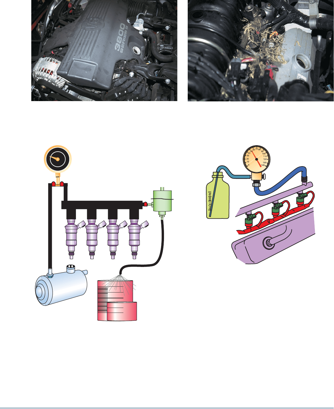
IDLE AIR CONTROL MOTOR (IAC)
THROTTLE
VALVE
AIR BYPASS
PASSAGE
AIRFLOW
(NORMAL IDLE POSITION)
AIR BYPASS
PASSAGE
(FULLY EXTENDED POSITION)
FIGURE 23–21 An idle air control (IAC) controls idle speed
by controlling theamount of air that passes around the throttle
plate. More airflow results in a higher idle speed.
FIGURE 23–22 A typical idle air control (IAC).
FIGURE 23–23 Some idle air control (IAC) units are pur-
chased with the housing as shown. Carbon buildup in these
passages can cause a rough or unstable idling or stalling.
There Is No Substitute for a Thorough Visual
Inspection
An intermittent “check engine” light and a random-
misfire diagnostic trouble code (DTC) P0300 was
being diagnosed. A scan tool did not provide any help
because all systems seemed to be functioning nor-
mally. Finally, the technician removed the engine cover
and discovered a mouse nest.
SEE FIGURE 23–24.
REAL WORLD FIX
After many years of fuel-injection service, some service tech-
nicians still misunderstand the process of proper fuel-system
handling. Much has been said over the years with regard to
when and how to perform injector cleaning. Some manufac-
turers have suggested methods of cleaning, while others have
issued bulletins to prohibit any cleaning at all.
All engines using fuel injection do require some type of fuel-
system maintenance. Normal wear and tear with today’s under-
hood temperatures and changes in gasoline quality contribute to
the buildup of olefin wax, dirt, water, and many other additives.
Unique to each engine is an air-control design that also may
contribute different levels of carbon deposits, such as oil control.
Fuel-injection system service should include the following
operations:
1. Check fuel-pump operating pressure and volume. The
missing link here is volume. Most working technicians
FUEL-INJECTION SERVICE
assume that if the pressure is correct, the volume is also
okay. Hook up a fuel-pressure tester to the fuel rail inlet to
quickly test the fuel pressure with the engine running. At the
same time, test the volume of the pump by sending fuel into
the holding tank. (One ounce per second is the usual speci-
fication.)
SEE FIGURE 23–25 . A two-line system tester is
the recommended procedure to use and is attached to the
fuel inlet and the return on the fuel rail. The vehicle onboard
system is looped and returns fuel to the tank.
2. Test the fuel-pressure regulator for operation and
leakage. At this time, the fuel-pressure regulator would
be tested for operational pressure and proper regulation,
including leakage. (This works well, as the operator has to-
tal control of rail pressure with a unit control valve.) Below
are some points to ponder:
Good pressure does not mean proper volume. For
example, a clogged filter may test okay on pressure,
but the restriction may not allow proper volume under
load.
SEE FIGURE 23–26 .
FUEL-INJECTION SYSTEM DIAGNOSIS AND SERVICE 297
It is a good idea to use the vehicle’s own gasoline to
service the system versus a can of shop gasoline that
has been sitting around for some time.
Pressure regulators do fail, and a lot more do not
properly shut off fuel, causing higher-than-normal
pump wear and shorter service life.
(a)
(b)
FIGURE 23–24 (a) Nothing looks unusual when the hood is first opened. (b) When the cover is removed from the top of the en-
gine, a mouse or some other animal nest is visible. The animal had already eaten through a couple of injector wires. At least the
cause of the intermittent misfire was discovered.
ONE OUNCE
PER SECOND
REGULATOR
FUEL GAUGE
FUEL VOLUME TEST
0
1
10
2
9
3
8
4
7
5
6
Bar
FIGURE 23–25 Checking fuel-pump volume using a hose
from the outlet of the fuel-pressure regulator into a calibrated
container.
FIGURE 23–26 Testing fuel-pump volume using a fuel-
pressure gauge with a bleed hose inserted into a suitable con-
tainer. The engine is running during this test.
3. Flush the entire fuel rail and upper fuel-injector screens,
including the fuel-pressure regulator. Raise the input
pressure to a point above regulator setting to allow a con-
stant flow of fuel through the inlet pressure side of the
system, through the fuel rail, and out the open fuel-pressure
regulator. In most cases the applied pressure is 75 to 90PSI
(517 to 620 kPa) but will be maintained by the presence of
a regulator. At this point, cleaning chemical is added to the
fuel at a 5:1 mixture and allowed to flow through the system
for 15 to 30 minutes.
SEE FIGURE 23–27 . Results are
best on a hot engine with the fuel supply looped and the
engine not running. Below are some points to ponder:
This flush is the fix most vehicles need first. The differ-
ence is that the deposits are removed to a remote tank
298 CHAPTER 23
This service usually takes approximately one hour for the vehicle
to run out of fuel and the entire service to be performed. The
good thing is that the technician may do other services while this
is being performed. Some technicians may install a set of plugs
or change the fuel filter while the engine is flushing. This service
should restore the fuel system to original operations.
and filter versus attempting to soften the deposits and
blow them through the upper screens.
Most injectors use a 10-micron final filter screen. A
25% restriction in the upper screen would increase the
injector on-time approximately 25%.
Clean the fuel injectors. Start the engine and adjust
the output pressure closer to regulator pressure or
lower than in the previous steps. Lower pressure will
cause the pulse width to open up somewhat longer
and allow the injectors to be cleaned. Slow speed (idle)
position will take a longer time frame, and operating
temperature will be reached. Clean injectors are the
objective, but the chemical should also decarbon the
engine valves, pistons, and oxygen sensor.
4. Decarbon the engine assembly. On most vehicles, the
injector spray will help the decarboning process. On oth-
ers, you may need to enhance the operation with external
addition of a mixture through the PCV hose, throttle plates,
or IACs.
5. Clean the throttle plate and IAC passages. Doing this
service alone on most late-model engines will show a
manifold vacuum increase of up to 2 in. Hg. Stop the en-
gine and clean the areas as needed, then use a handheld
fuel injector connected in parallel with the pressure hose,
along with a pulser to allow cleaning of the throttle plates
with the same chemical as injectors are running on.
SEE
FIGURE 23–28 . This works well, as air is drawn into IAC
passages on a running engine and will clean the passages
without IAC removal.
6. Relearn the onboard computer. Some vehicles may have
been running in such a poor state of operation that the on-
board computer may need to be relearned. Consult service
information for the suggested relearn procedures for each
particular vehicle.
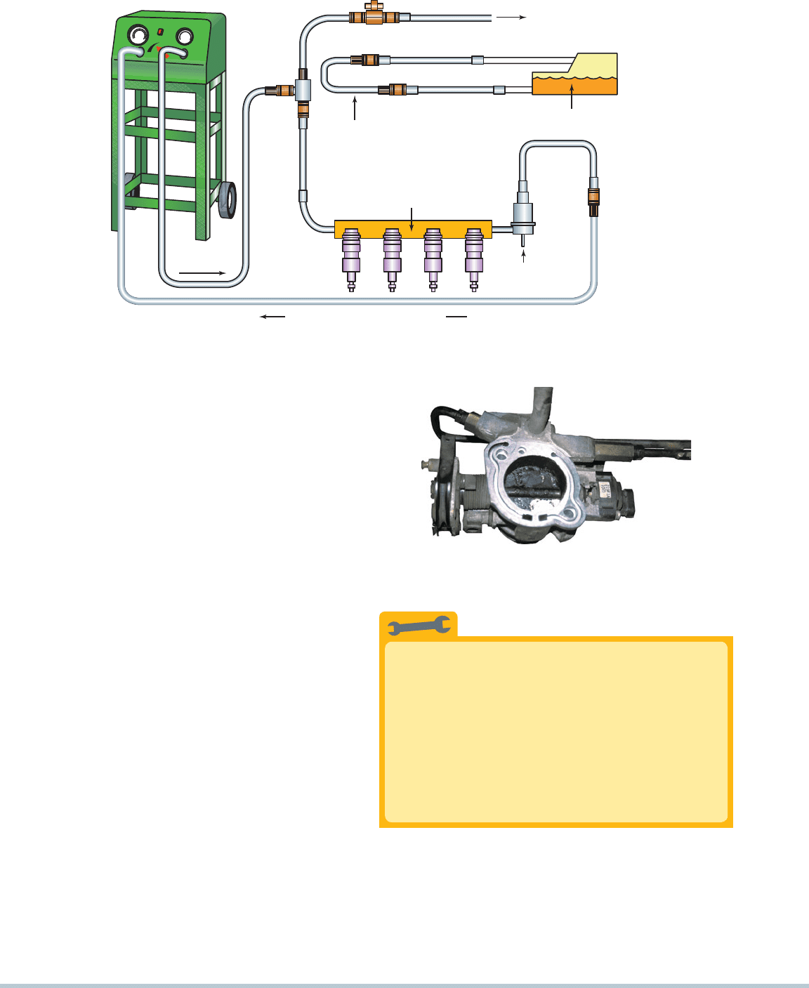
CLEANING
SOLUTION
FUEL SUPPLY AND RETURN
LINES DISCONNECTED FROM
SYSTEM AND LOOPED TOGETHER
FUEL TANK
FUEL RAIL
VACUUM
LINE
DISCONNECTED
CLEANING SOLUTION RETURN
TO PLENUM
CLEANER NOZZLE
FIGURE 23–27 A typical two-line cleaning machine hookup, showing an extension hose that can be used to squirt a cleaning
solution into the throttle body while the engine is running on the cleaning solution and gasoline mixture.
FIGURE 23–28 To thoroughly clean a throttle body, it is
sometimes best to remove it from the vehicle.
Check the Injectors at the “Bends
and the Ends”
Injectors that are most likely to become restricted
because of clogging of the filter basket screen are the
injectors at the ends of the rail, especially on returnless
systems where dirt can accumulate. Also, the injectors
that are located at the bends of the fuel rail are
subject to possible clogging because of the dirt being
deposited where the fuel makes a turn in the rail.
TECH TIP
FUEL-INJECTION SYSTEM DIAGNOSIS AND SERVICE 299
All of the previously listed steps may be performed using a
two-line fuel-injector service unit, such as Carbon Clean, Auto
Care, Injector Test, DeCarbon, or Motor-Vac.
Fuel-Injection Symptom Chart
Symptom Possible Causes
Hard cold starts • Low fuel pressure
• Leaking fuel injectors
• Contaminated fuel
• Low-volatility fuel
• Dirty throttle plate
Garage stalls • Low fuel pressure
• Insufficient fuel volume
• Restricted fuel injector
• Contaminated fuel
• Low-volatility fuel
Poor cold performance • Low fuel pressure
• Insufficient fuel volume
• Contaminated fuel
• Low-volatility fuel
Tip-in hesitation (hesitation
just as the accelerator pedal is
depressed)
• Low fuel pressure
• Insufficient fuel volume
• Intake valve deposits
• Contaminated fuel
• Low-volatility fuel
Be Sure to Clean the Fuel Rail
Whenever you service the fuel injectors or if you
suspect that there may be a fuel-injector problem,
remove the entire fuel rail assembly and check the
passages for contamination. Always thoroughly
clean the rail when replacing fuel injectors.
TECH TIP
Condition
Long-Term Fuel
Trim at Idle
Long-Term Fuel
Trim at 3,000 RPM
System normal
0% 10% 0% 10%
Vacuum leak HIGH OK
Fuel flow problem OK HIGH
Low fuel pressure HIGH HIGH
High fuel pressure *OK or LOW *OK or LOW
*High fuel pressure will affect trim at idle, at 3,000 RPM, or both.
FUEL-SYSTEM SCAN
TOOL DIAGNOSTICS
Diagnosing a faulty fuel system can be a difficult task. However,
it can be made easier by utilizing the information available via
the serial data stream. By observing the long-term fuel trim and
the short-term fuel trim, we can determine how the fuel system
is performing. Short-term fuel trim and long-term fuel trim can
help us to zero in on specific areas of trouble. Readings should
be taken at idle and at 3,000 RPM. Use the following chart as
a guide:
300 CHAPTER 23
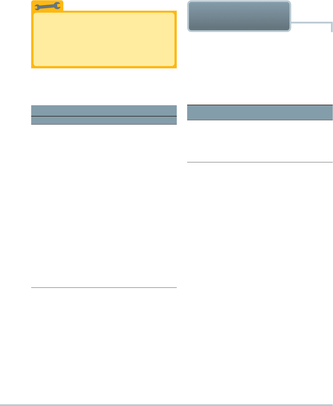
The tools needed to diagnose a circuit containing a re-
lay include a digital multimeter (DMM), a fused jumper
wire, and an assortment of wiring terminals.
1
Start the diagnosis by locating the relay center. It is un-
der the hood on this General Motors vehicle, so access
is easy. Not all vehicles are this easy.
2
The chart under the cover for the relay center indicates
the location of the relay that controls the electric fuel
pump.
3
Locate the fuel-pump relay and remove by using a
puller if necessary. Try to avoid rocking or twisting
the relay to prevent causing damage to the relay
terminals or the relay itself.
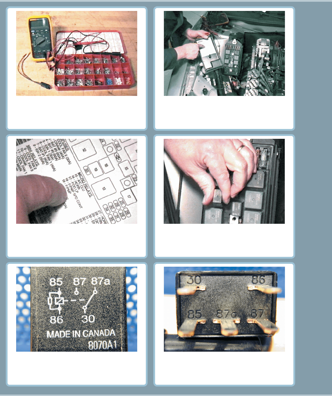
4
Terminals 85 and 86 represent the coil inside the
relay. Terminal 30 is the power terminal, 87a is the
normally closed contact, and 87 is the normally
open contact.
5
The terminals are also labeled on most relays.
6
FUEL-PUMP RELAY CIRCUIT DIAGNOSIS