Harris C.M., Piersol A.G. Harris Shock and vibration handbook
Подождите немного. Документ загружается.

When the moments and product of inertia with respect to a pair of axes X and Z
in a principal plane of inertia XZ are known, the orientation of a principal axis P is
given by
θ
p
=
1
⁄2 tan
−1
(3.29)
where θ
p
is the counterclockwise angle from the X axis to the P axis. The second
principal axis in this plane is at θ
p
+ 90°.
Consider the determination of products of inertia when the directions of all
principal axes of inertia are unknown. In one method, the moments of inertia about
two independent sets of three mutually perpendicular axes are measured, and the
direction cosines between these sets of axes are known from the positions of the
axes. The values for the six moments of inertia and the nine direction cosines are
then substituted into Eqs. (3.16) and (3.17). The result is six linear equations in the
six unknown products of inertia, from which the values of the desired products of
inertia may be found by simultaneous solution of the equations. This method leads
to experimental errors of relatively large magnitude because each product of iner-
tia is, in general, a function of all six moments of inertia, each of which contains an
experimental error.
An alternative method is based upon the knowledge that one of the principal
moments of inertia of a body is the largest and another is the smallest that can be
obtained for any axis through the center-of-gravity. A trial-and-error procedure can
be used to locate the orientation of the axis through the center-of-gravity having the
maximum and/or minimum moment of inertia. After one or both are located, the
moments and products of inertia for any set of axes are found by the techniques pre-
viously discussed.
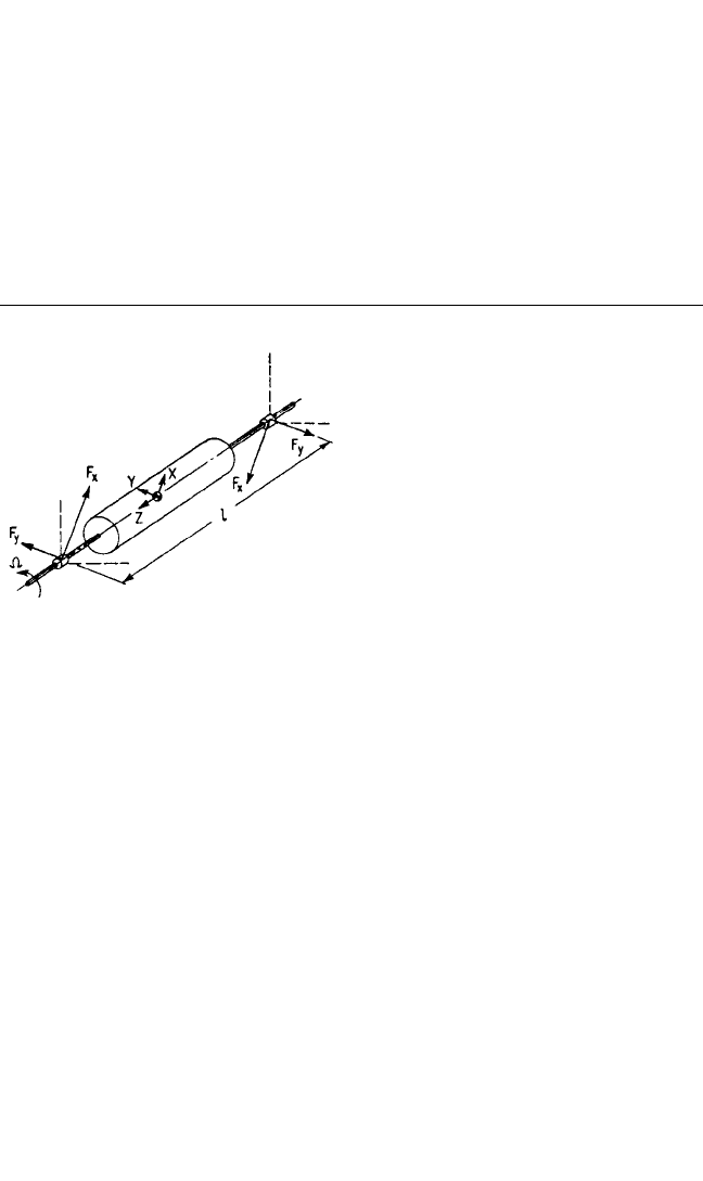
The products of inertia of a body also may be determined by rotating the body at
a constant angular velocity Ω about an axis passing through the center-of-gravity, as
illustrated in Fig. 3.10. This method is similar to the balancing machine technique
used to balance a body dynamically (see Chap. 39). If the bearings are a distance l
apart and the dynamic reactions F
x
and F
y
are measured, the products of inertia are
2I
xz
I
zz
− I
xx
VIBRATION OF A RESILIENTLY SUPPORTED RIGID BODY 3.21
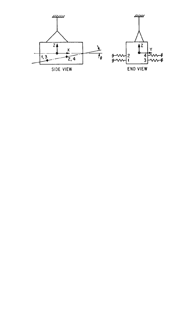
FIGURE 3.9 Method of determining the product of inertia with
respect to the axes X and Z when Y is a principal axis of inertia.The
test body is oscillated about the vertical Z axis with torsional stiff-
ness provided by the four springs acting in the Y direction at the
points shown.There should be no net force on the test body in the Y
direction due to a rotation about the Z axis. The angle θ is varied
until, at some value of θ=θ
0
, oscillations about X and Z are uncou-
pled.The angle θ
0
and the moment of inertia about the Z axis give I
xz
by Eq. (3.28).
8434_Harris_03_b.qxd 09/20/2001 11:32 AM Page 3.21
I
xz
=− I
yz
=− (3.30)
Limitations to this method are (1) the size of the body that can be accommodated
by the balancing machine and (2) the angular velocity that the body can withstand
without damage from centrifugal forces. If the angle between the Z axis and a prin-
cipal axis of inertia is small, high rotational speeds may be necessary to measure the
reaction forces accurately.
PROPERTIES OF RESILIENT SUPPORTS
A resilient support is considered to be a
three-dimensional element having two
terminals or end connections. When the
end connections are moved one relative
to the other in any direction, the ele-
ment resists such motion. In this chap-
ter, the element is considered to be
massless; the force that resists relative
motion across the element is considered
to consist of a spring force that is
directly proportional to the relative dis-
placement (deflection across the ele-
ment) and a damping force that is
directly proportional to the relative
velocity (velocity across the element).
Such an element is defined as a linear
resilient support. Nonlinear elements are
discussed in Chap. 4; elements with mass
are discussed in Chap. 30; and nonlinear
damping is discussed in Chaps. 2 and 30.
In a single degree-of-freedom system or in a system having constraints on the
paths of motion of elements of the system (Chap. 2), the resilient element is con-
strained to deflect in a given direction and the properties of the element are defined
with respect to the force opposing motion in this direction. In the absence of such
constraints, the application of a force to a resilient element generally causes a
motion in a different direction. The principal elastic axes of a resilient element are
those axes for which the element, when unconstrained, experiences a deflection co-
lineal with the direction of the applied force. Any axis of symmetry is a principal
elastic axis.
In rigid body dynamics, the rigid body sometimes vibrates in modes that are cou-
pled by the properties of the resilient elements as well as by their location. For
example, if the body experiences a static displacement x in the direction of the X
axis only, a resilient element opposes this motion by exerting a force k
xx
x on the
body in the direction of the X axis, where one subscript on the spring constant k
indicates the direction of the force exerted by the element and the other subscript
indicates the direction of the deflection. If the X direction is not a principal elastic
direction of the element and the body experiences a static displacement x in the X
direction, the body is acted upon by a force k
yx
x in the Y direction if no displacement
y is permitted. The stiffnesses have reciprocal properties; i.e., k
xy
= k
yx
. In general,
F
y
l
Ω
2
F
x
l
Ω
2
3.22 CHAPTER THREE
FIGURE 3.10 Balancing machine technique
for determining products of inertia. The test
body is rotated about the Z axis with angular
velocity Ω. The dynamic reactions F
x
and F
y
measured at the bearings, which are a distance l
apart, give I
xz
and I
yz
by Eq. (3.30).
8434_Harris_03_b.qxd 09/20/2001 11:32 AM Page 3.22

the stiffnesses in the directions of the coordinate axes can be expressed in terms of
(1) principal stiffnesses and (2) the angles between the coordinate axes and the
principal elastic axes of the element. (See Chap. 30 for a detailed discussion of a
biaxial stiffness element.) Therefore, the stiffness of a resilient element can be rep-
resented pictorially by the combination of three mutually perpendicular, idealized
springs oriented along the principal elastic directions of the resilient element. Each
spring has a stiffness equal to the principal stiffness represented.
A resilient element is assumed to have damping properties such that each spring
representing a value of principal stiffness is paralleled by an idealized viscous
damper, each damper representing a value of principal damping. Hence, coupling
through damping exists in a manner similar to coupling through stiffness. Conse-
quently, the viscous damping coefficient c is analogous to the spring coefficient k;
i.e., the force exerted by the damping of the resilient element in response to a veloc-
ity ˙x is c
xx
˙x in the direction of the X axis and c
yx
˙x in the direction of the Y axis if ˙y is
zero. Reciprocity exists; i.e., c
xy
= c
yx
.
The point of intersection of the principal elastic axes of a resilient element is des-
ignated as the elastic center of the resilient element. The elastic center is important
since it defines the theoretical point location of the resilient element for use in the
equations of motion of a resiliently supported rigid body. For example, the torque on
the rigid body about the Y axis due to a force k
xx
x transmitted by a resilient element
in the X direction is k
xx
a
z
x, where a
z
is the Z coordinate of the elastic center of the
resilient element.
In general, it is assumed that a resilient element is attached to the rigid body by
means of “ball joints”; i.e., the resilient element is incapable of applying a couple to
the body. If this assumption is not made, a resilient element would be represented
not only by translational springs and dampers along the principal elastic axes but
also by torsional springs and dampers resisting rotation about the principal elastic
directions.
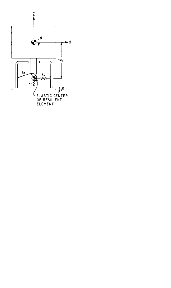
Figure 3.11 shows that the torsional elements usually can be neglected. The
torque which acts on the rigid body due to a rotation β of the body and a rotation b
of the support is (k
t
+ a
z
2
k
x
) (β−b), where k
t
is the torsional spring constant in the β
direction. The torsional stiffness k
t
usually is much smaller than a
z
2
k
x
and can be ne-
glected.Treatment of the general case indicates that if the torsional stiffnesses of the
resilient element are small compared with the product of the translational stiffnesses
times the square of distances from the elastic center of the resilient element to the
center-of-gravity of the rigid body, the torsional stiffnesses have a negligible effect
on the vibrational behavior of the body. The treatment of torsional dampers is com-
pletely analogous.
EQUATIONS OF MOTION FOR A RESILIENTLY
SUPPORTED RIGID BODY
The differential equations of motion for the rigid body are given by Eqs. (3.2) and
(3.3), where the F’s and M’s represent the forces and moments acting on the body,
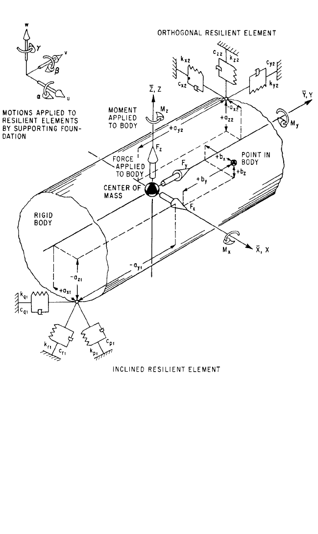
either directly or through the resilient supporting elements. Figure 3.12 shows a view
of a rigid body at rest with an inertial set of axes
X,
Y,
Z and a coincident set of axes
X,Y, Z fixed in the rigid body, both sets of axes passing through the center-of-mass. A
typical resilient element (2) is represented by parallel spring and viscous damper
combinations arranged respectively parallel with the
X,
Y,
Z axes. Another resilient
element (1) is shown with its principal axes not parallel with
X,
Y,
Z.
VIBRATION OF A RESILIENTLY SUPPORTED RIGID BODY 3.23
8434_Harris_03_b.qxd 09/20/2001 11:32 AM Page 3.23
The displacement of the center-of-
gravity of the body in the
X,
Y,
Z direc-
tions is in Fig. 3.1 indicated by x
c
,y
c
,z
c
,
respectively; and rotation of the rigid
body about these axes is indicated by a,
b, g, respectively. In Fig. 3.12, each
resilient element is represented by three
mutually perpendicular spring-damper
combinations. One end of each such
combination is attached to the rigid
body; the other end is considered to
be attached to a foundation whose cor-
responding translational displacement is
defined by u, v, w in the
X,
Y,
Z di-
rections, respectively, and whose rota-
tional displacement about these axes is
defined by a, b, g, respectively. The point
of attachment of each of the idealized
resilient elements is located at the coor-
dinate distances a
x
,a
y
,a
z
of the elastic
center of the resilient element.
Consider the rigid body to experi-
ence a translational displacement x
c
of
its center-of-gravity and no other dis-
placement, and neglect the effects of the
viscous dampers.The force developed by a resilient element has the effect of a force
−k
xx
(x
c
− u) in the X direction, a moment k
xx
(x
c
− u)a
y
in the γ coordinate (about the
Z axis), and a moment −k
xx
(x
c
− u)a
z
in the β coordinate (about the Y axis). Further-
more, the coupling stiffness causes a force −k
xy
(x
c
− u) in the Y direction and a force
−k
xz
(x
c
− u) in the Z direction. These forces have the moments k
xy
(x
c
− u)a
z
in the α
coordinate; −k
xy
(x
c
− u)a
x
in the γ coordinate; k
xz
(x
c
− u)a
x
in the β coordinate; and
−k
xz
(x
c
− u)a
y
in the α coordinate. By considering in a similar manner the forces and
moments developed by a resilient element for successive displacements of the rigid
body in the three translational and three rotational coordinates, and summing over
the number of resilient elements, the equations of motion are written as follows:
6, 7
m¨x
c
+Σk
xx
(x
c
− u) +Σk
xy
(y
c
− v) +Σk
xz
(z
c
− w)
+Σ(k
xz
a
y
− k
xy
a
z
)(α−a) +Σ(k
xx
a
z
− k
xz
a
x
)(β−b)
+Σ(k
xy
a
x
− k
xx
a
y
)(γ−g) = F
x
(3.31a)
I
xx
¨α−I
xy
¨
β−I
xz
¨γ+Σ(k
xz
a
y
− k
xy
a
z
)(x
c
− u)
+Σ(k
yz
a
y
− k
yy
a
z
)(y
c
− v) +Σ(k
zz
a
y
− k
yz
a
z
)(z
c
− w)
+Σ(k
yy
a
z
2
+ k
zz
a
y
2
− 2k
yz
a
y
a
z
)(α−a)
+Σ(k
xz
a
y
a
z
+ k
yz
a
x
a
z
− k
zz
a
x
a
y
− k
xy
a
z
2
)(β−b)
+Σ(k
xy
a
y
a
z
+ k
yz
a
x
a
y
− k
yy
a
x
a
z
− k
xz
a
y
2
)(γ−g) = M
x
(3.31b)
mÿ
c
+Σk
xy
(x
c
− u) +Σk
yy
(y
c
− v) +Σk
yz
(z
c
− w)
+Σ(k
yz
a
y
− k
yy
a
z
)(α−a) +Σ(k
xy
a
z
− k
yz
a
x
)(β−b)
+Σ(k
yy
a
x
− k
xy
a
y
)(γ−g) = F
y
(3.31c)
3.24 CHAPTER THREE
FIGURE 3.11 Pictorial representation of the
properties of an undamped resilient element in
the XZ plane including a torsional spring k
t
. An
analysis of the motion of the supported body in
the XZ plane shows that the torsional spring can
be neglected if k
t
<< a
z
2
k
x
.
8434_Harris_03_b.qxd 09/20/2001 11:32 AM Page 3.24
I
yy
¨
β−I
xy
¨α−I
yz
¨γ+Σ(k
xx
a
z
− k
xz
a
x
)(x
c
− u)
+Σ(k
xy
a
z
− k
yz
a
x
)(y
c
− v) +Σ(k
xz
a
z
− k
zz
a
x
)(z
c
− w)
+Σ(k
xz
a
y
a
z
+ k
yz
a
x
a
z
− k
zz
a
x
a
y
− k
xy
a
z
2
)(α−a)
+Σ(k
xx
a
z
2
+ k
zz
a
x
2
− 2k
xz
a
x
a
z
)(β−b)
+Σ(k
xy
a
x
a
z
+ k
xz
a
x
a
y
− k
xx
a
y
a
z
− k
yz
a
x
2
)(γ−g) = M
y
(3.31d)
VIBRATION OF A RESILIENTLY SUPPORTED RIGID BODY 3.25
FIGURE 3.12 Rigid body at rest supported by resilient elements, with inertial axes
X,
Y,
Z and
coincident reference axes X, Y, Z passing through the center-of-mass. The forces F
x
,F
y
,F
z
and the
moments M
x
,M
y
,M
z
are applied directly to the body; the translations u, v, w and rotations a, b, g in
and about the X, Y, Z axes, respectively, are applied to the resilient elements located at the coordi-
nates a
x
,a
y
,a
z
. The principal directions of resilient element (2) are parallel to the
X,
Y,
Z axes
(orthogonal), and those of resilient element (1) are not parallel to the
X,
Y,
Z axes (inclined).
8434_Harris_03_b.qxd 09/20/2001 11:32 AM Page 3.25

m¨z
c
+Σk
xz
(x
c
− u) +Σk
yz
(y
c
− v) +Σk
zz
(z
c
− w)
+Σ(k
zz
a
y
− k
yz
a
z
)(α−a) +Σ(k
xz
a
z
− k
zz
a
x
)(β−b)
+Σ(k
yz
a
x
− k
xz
a
y
)(γ−g) = F
z
(3.31e)
I
zz
¨γ−I
xz
¨α−I
yz
¨
β+Σ(k
xy
a
x
− k
xx
a
y
)(x
c
− u)
+Σ(k
yy
a
x
− k
xy
a
y
)(y
c
− v) +Σ(k
yz
a
x
− k
xz
a
y
)(z
c
− w)
+Σ(k
xy
a
y
a
z
+ k
yz
a
x
a
y
− k
yy
a
x
a
z
− k
xz
a
y
2
)(α−a)
+Σ(k
xy
a
x
a
z
+ k
xz
a
x
a
y
− k
xx
a
y
a
z
− k
yz
a
x
2
)(β−b)
+Σ(k
xx
a
y
2
+ k
yy
a
x
2
− 2k
xy
a
x
a
y
)(γ−g) = M
z
(3.31f )
where the moments and products of inertia are defined by Eqs. (3.11) and (3.12) and
the stiffness coefficients are defined as follows:
k
xx
= k
p
λ
xp
2
+ k
q
λ
xq
2
+ k
r
λ
xr
2
k
yy
= k
p
λ
yp
2
+ k
q
λ
yq
2
+ k
r
λ
yr
2
k
zz
= k
p
λ
zp
2
+ k
q
λ
zq
2
+ k
r
λ
zr
2
k
xy
= k
p
λ
xp
λ
yp
+ k
q
λ
xq
λ
yq
+ k
r
λ
xr
λ
yr
(3.32)
k
xz
= k
p
λ
xp
λ
zp
+ k
q
λ
xq
λ
zq
+ k
r
λ
xr
λ
zr
k
yz
= k
p
λ
yp
λ
zp
+ k
q
λ
yq
λ
zq
+ k
r
λ
yr
λ
zr
where the λ’s are the cosines of the angles between the principal elastic axes of the
resilient supporting elements and the coordinate axes. For example, λ
xp
is the cosine
of the angle between the X axis and the P axis of principal stiffness.
The equations of motion, Eqs. (3.31), do not include forces applied to the rigid
body by damping forces from the resilient elements. To include damping, appropri-
ate damping terms analogous to the corresponding stiffness terms are added to each
equation. For example, Eq. (3.31a) would become
m¨x
c
+Σc
xx
(˙x
c
− ˙u) +Σk
xx
(x
c
− u) + ⋅⋅⋅
+Σ(c
xz
a
y
− c
xy
a
z
)(˙α−˙a ) +Σ(k
xz
a
y
− k
xy
a
z
)(α−a) + ⋅⋅⋅ = F
x
(3.31a′ )
where c
xx
= c
p
λ
xp
2
+ c
q
λ
xq
2
+ c
r
λ
xr
2
c
xy
= c
p
λ
xp
λ
yp
+ c
q
λ
xq
λ
yq
+ c
r
λ
xr
λ
yr
The number of degrees-of-freedom of a vibrational system is the minimum num-
ber of coordinates necessary to define completely the positions of the mass elements
of the system in space. The system of Fig. 3.12 requires a minimum of six coordinates
(x
c
,y
c
,z
c
,α,β,γ) to define the position of the rigid body in space; thus, the system is
said to vibrate in six degrees-of-freedom. Equations (3.31) may be solved simulta-
neously for the three components x
c
,y
c
,z
c
of the center-of-gravity displacement and
the three components α, β, γ of the rotational displacement of the rigid body. In most
practical instances, the equations are simplified considerably by one or more of the
following simplifying conditions:
1. The reference axes X,Y, Z are selected to coincide with the principal inertial axes
of the body; then
3.26 CHAPTER THREE
8434_Harris_03_b.qxd 09/20/2001 11:32 AM Page 3.26

I
xy
= I
xz
= I
yz
= 0 (3.33)
2. The resilient supporting elements are so arranged that one or more planes of
symmetry exist; i.e., motion parallel to the plane of symmetry has no tendency to
excite motion perpendicular to it, or rotation about an axis lying in the plane
does not excite motion parallel to the plane. For example, in Eq. (3.31a), motion
in the XY plane does not tend to excite motion in the XZ or YZ plane if Σk
xz
,
Σ(k
xz
a
y
− k
xy
a
z
), and Σ(k
xx
a
z
− k
xz
a
x
) are zero.
3. The principal elastic axes P, Q , R of all resilient supporting elements are orthog-
onal with the reference axes X,Y, Z of the body, respectively. Then, in Eqs. (3.32),
k
xx
= k
p
= k
x
k
yy
= k
q
= k
y
k
zz
= k
r
= k
z
k
xy
= k
xz
= k
yz
= 0
(3.34)
where k
x
,k
y
,k
z
are defined for use when orthogonality exists. The supports are
then called orthogonal supports.
4. The forces F
x
,F
y
,F
z
and moments M
x
,M
y
,M
z
are applied directly to the body and
there are no motions (u = v = w = a = b = g = 0) of the foundation; or alternatively,
the forces and moments are zero and excitation results from motion of the foun-
dation.
In general, the effect of these simplifications is to reduce the numbers of terms in the
equations and, in some instances, to reduce the number of equations that must be
solved simultaneously. Simultaneous equations indicate coupled modes; i.e., motion
cannot exist in one coupled mode independently of motion in other modes which
are coupled to it.
MODAL COUPLING AND NATURAL
FREQUENCIES
Several conditions of symmetry resulting from zero values for the product of inertia
terms in Eq. (3.33) are discussed in the following sections.
ONE PLANE OF SYMMETRY WITH ORTHOGONAL RESILIENT
SUPPORTS
When the YZ plane of the rigid body system in Fig. 3.12 is a plane of symmetry, the
following terms in the equations of motion are zero:
Σk
yy
a
x
=Σk
zz
a
x
=Σk
yy
a
x
a
z
=Σk
zz
a
x
a
y
= 0 (3.35)
Introducing the further simplification that the principal elastic axes of the resilient
elements are parallel with the reference axes, Eqs. (3.34) apply. Then the motions in
the three coordinates y
c
,z
c
, α are coupled but are independent of motion in any of
the other coordinates; furthermore, the other three coordinates x
c
, β, γ also are cou-
pled. For example, Fig. 3.13 illustrates a resiliently supported rigid body, wherein the
YZ plane is a plane of symmetry that meets the requirements of Eq. (3.35).The three
natural frequencies for the y
c
,z
c
, α coupled directions are found by solving Eqs.
VIBRATION OF A RESILIENTLY SUPPORTED RIGID BODY 3.27
8434_Harris_03_b.qxd 09/20/2001 11:32 AM Page 3.27

(3.31b), (3.31c), and (3.31e) [or Eqs. (3.31a), (3.31d), and (3.31f) for the x
c
, β, γ cou-
pled directions] simultaneously.
6
6
− A
4
+ B
2
− C = 0 (3.36)
where f
z
=
(3.37)
is a quantity having mathematical rather than physical significance if translational
motion in the direction of the Z axis is coupled to other modes of motion. (Such cou-
pling exists for the system of Fig. 3.13.) The roots f
n
represent the natural frequencies
of the system in the coupled modes. The coefficients A, B, C for the coupled modes
in the y
c
,z
c
, α coordinates are
A
yzα
= 1 ++D
zx
B
yzα
= D
zx
+ (1 + D
zx
) −
C
yzα
=
D
zx
−
−
where D
zx
=
and ρ
x
is the radius of gyration of the rigid body with respect to the X axis.
The corresponding coefficients for the coupled modes in the x
c
, β, γ coordinates are
A
xβγ
=+D
zy
+ D
zz
B
xβγ
= (D
zy
+ D
zz
) + D
zy
D
zz
−−−
C
xβγ
=
D
zy
D
zz
−
− D
zy
− D
zz
+ 2
where D
zy
= D
zz
=
and ρ
y
, ρ
z
are the radii of gyration of the rigid body with respect to the Y, Z axes.
The roots of the cubic equation Eq. (3.36) may be found graphically from Fig.
3.14.
6
The coefficients A, B, C are first calculated from the above relations for the
appropriate set of coupled coordinates. Figure 3.14 is entered on the abscissa scale
at the appropriate value for the quotient B/A
2
. Small values of B/A
2
are in Fig.
3.14A, and large values in Fig. 3.14B. The quotient C/A
3
is the parameter for the
family of curves. Upon selecting the appropriate curve, three values of (f
n
/f
z
)/A
Σk
x
a
y
2
+Σk
y
a
x
2
ρ
z
2
Σk
z
Σk
x
a
z
2
+Σk
z
a
x
2
ρ
y
2
Σk
z
(Σk
x
a
y
)(Σk
x
a
z
)(Σk
x
a
y
a
z
)
ρ
y
2
ρ
z
2
(Σk
z
)
3
(Σk
x
a
z
)
2
ρ
y
2
(Σk
z
)
2
(Σk
x
a
y
)
2
ρ
z
2
(Σk
z
)
2
(Σk
x
a
y
a
z
)
2
ρ
y
2
ρ
z
2
(Σk
z
)
2
Σk
x
Σk
z
(Σk
x
a
y
a
z
)
2
ρ
y
2
ρ
z
2
(Σk
z
)
2
(Σk
x
a
y
)
2
ρ
z
2
(Σk
z
)
2
(Σk
x
a
z
)
2
ρ
y
2
(Σk
z
)
2
Σk
x
Σk
z
Σk
x
Σk
z
Σk
y
a
z
2
+Σk
z
a
y
2
ρ
x
2
Σk
z
(Σk
y
a
z
)
2
ρ
x
2
(Σk
z
)
2
(Σk
z
a
y
)
2
ρ
x
2
(Σk
z
)
2
Σk
y
Σk
z
(Σk
y
a
z
)
2
+ (Σk
z
a
y
)
2
ρ
x
2
(Σk
z
)
2
Σk
y
Σk
z
Σk
y
Σk
z
Σk
z
m
1
2π
f
n
f
z
f
n
f
z
f
n
f
z
3.28 CHAPTER THREE
8434_Harris_03_b.qxd 09/20/2001 11:32 AM Page 3.28
are read from the ordinate and trans-
ferred to the left scale of the nomo-
graph in Fig. 3.14B. Diagonal lines are
drawn for each root to the value of A on
the right scale, as indicated by dotted
lines, and the roots f
n
/f
z
of the equation
are indicated by the intercept of these
dotted lines with the center scale of the
nomograph.
The coefficients A, B, C can be sim-
plified if all resilient elements have
equal stiffness in the same direction.The
stiffness coefficients always appear to
equal powers in numerator and denomi-
nator, and lead to dimensionless ratios
of stiffness. For n resilient elements, typ-
ical terms reduce as follows:
==
=
2
, etc.
TWO PLANES OF SYMMETRY
WITH ORTHOGONAL RESILIENT
SUPPORTS
Two planes of symmetry may be achieved
if, in addition to the conditions of Eqs.
(3.33) to (3.35), the following terms of
Eqs. (3.31) are zero:
Σk
xx
a
y
=Σk
zz
a
y
=Σk
xx
a
y
a
z
= 0
(3.38)
Under these conditions, Eqs. (3.31) sep-
arate into two independent equations,
Eqs. (3.31e) and (3.31f ), and two sets
each consisting of two coupled equa-
tions [Eqs. (3.31a) and (3.31d); Eqs.
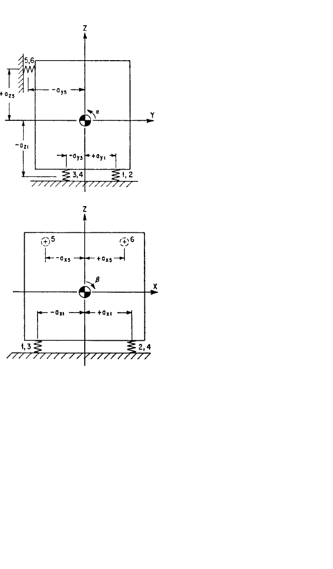
(3.31b) and (3.31c)]. The planes of symmetry are the XZ and YZ planes. For exam-
ple, a common system is illustrated in Fig. 3.15, where four identical resilient sup-
porting elements are located symmetrically about the Z axis in a plane not
containing the center-of-gravity.
6
Coupling exists between translation in the X direc-
tion and rotation about the Y axis (x
c
,β), as well as between translation in the Y
direction and rotation about the X axis (y
c
,α).Translation in the Z direction (z
c
) and
rotation about the Z axis (γ) are each independent of all other modes.
The natural frequency in the Z direction is found by solving Eq. (3.31e) to obtain
Eq. (3.37), where Σk
zz
= 4k
z
. The rotational natural frequency f
γ
about the Z axis is
found by solving Eq. (3.31f); it can be expressed with respect to the natural fre-
quency in the direction of the Z axis:
Σa
y
a
z
ρ
y
ρ
z
k
x
nk
z
(Σk
x
a
y
a
z
)
2
ρ
y
2
ρ
z
2
(Σk
z
)
2
Σa
y
2
nρ
x
2
Σk
z
a
y
2
ρ
x
2
Σk
z
k
y
k
z
Σk
y
Σk
z
VIBRATION OF A RESILIENTLY SUPPORTED RIGID BODY 3.29
FIGURE 3.13 Example of a rigid body on
orthogonal resilient supporting elements with
one plane of symmetry.The YZ plane is a plane of
symmetry since each resilient element has prop-
erties identical to those of its mirror image in the
YZ plane; i.e., k
x1
= k
x2
, k
x3
= k
x4
, k
x5
= k
x6
, etc. The
conditions satisfied are Eqs. (3.33) to (3.35).
8434_Harris_03_b.qxd 09/20/2001 11:32 AM Page 3.29
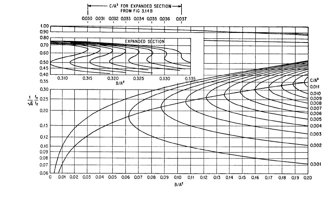
FIGURE 3.14A Graphical method of determining solutions of the cubic Eq.
(3.36). Calculate A, B, C for the
appropriate set of coupled coordinates, enter the abscissa at B/A
2
(values less than 0.2 on Fig. 3.14A, values greater
than 0.2 on Fig. 3.14B), and read three values of (f
n
/f
z
)/A
from the curve having the appropriate value of C/A
3
.
3.30
8434_Harris_03_b.qxd 09/20/2001 11:32 AM Page 3.30