Harris C.M., Piersol A.G. Harris Shock and vibration handbook
Подождите немного. Документ загружается.

also intersect at a common point on the Z axis, the angle between the Z axis and the
P axis for each element being 90°−φ. Consequently, the Q principal elastic axes are
each tangent to the circle of radius a
r
which bounds the end face of the cylinder.
The use of such a configuration permits decoupling of all six modes of vibration
of the rigid body. This complete decoupling is achieved if the angle of inclination φ
has the value φ′ which satisfies the following equation:
= (3.50)
(
1
⁄2)[1 − (k
p
/k
r
)] sin 2φ′
(k
q
/k
r
) + (k
p
/k
r
) + [1 − (k
p
/k
r
)] sin
2
φ′
a
z
a
r
VIBRATION OF A RESILIENTLY SUPPORTED RIGID BODY 3.41
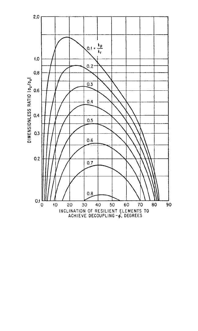
FIGURE 3.23 Curves showing the angle of inclination φ′ of the resilient
elements which achieves decoupling of the x
c
, β motions in Fig. 3.21 [see
Eq. (3.47)]. Calculate the ordinate |a
z
/a
x
| and with the stiffness ratio k
p
/k
r
determine two values of φ′ for which decoupling is possible. Decoupling is
not possible for a particular value of k
p
/k
r
if |a
z
/a
y
| has a value greater than
the maximum ordinate of the k
p
/k
r
curve.
8434_Harris_03_b.qxd 09/20/2001 11:32 AM Page 3.41
Since complete decoupling is effected, the system may be termed an “equivalent
center-of-gravity system.”
9, 10
The natural frequencies of the six decoupled modes are
==
cos
2
φ′ + sin
2
φ′ +
(3.51)
==
sin φ′
sin φ′ + cos φ′
+ cos φ′
cos φ′ − sin φ′
1/2
(3.52)
=
(3.53)
The frequency ratio f
z
/f
r
is given by Eq.
(3.43) or Fig. 3.22. The fictitious natural
frequency f
r
is given by
f
r
= (1/2π)
nk
r
/m
Similar solutions are also available for
the configuration of four resilient sup-
ports located in a rectangular array and
inclined to achieve complete decou-
pling.
11
FORCED VIBRATION
Forced vibration results from a continu-
ing excitation that varies sinusoidally
with time.The excitation may be a vibra-
tory displacement of the foundation for
the resiliently supported rigid body
(foundation-induced vibration), or a
force or moment applied to or gener-
ated within the rigid body (body-
induced vibration). These two forms of
excitation are considered separately.
FOUNDATION-INDUCED SINUSOIDAL VIBRATION
This section includes an analysis of foundation-induced vibration for two different
systems, each having two planes of symmetry. In one system, the principal elastic
axes of the resilient elements are parallel to the X,Y, Z axes; in the other system, the
principal elastic axes are inclined with respect to two of the axes but in a plane par-
allel to one of the reference planes. The excitation is translational movement of the
foundation in its own plane, without rotation. No forces or moments are applied
a
r
ρ
z
k
q
k
r
f
γ
f
r
a
z
ρ
x
a
r
ρ
x
a
z
ρ
x
a
r
ρ
x
k
p
k
r
a
r
2ρ
x
f
β
f
r
f
α
f
r
k
q
k
r
k
p
k
r
1
2
f
y
f
r
f
x
f
r
3.42 CHAPTER THREE
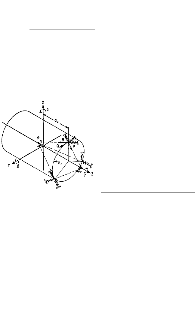
FIGURE 3.24 Example of a rigid cylindrical
body on radially inclined resilient supports. The
resilient supports are attached symmetrically
about the Z axis to one end face of the cylinder
at a distance a
r
from the Z axis and a distance a
z
from the XY plane. The resilient elements are
inclined so that their principal elastic axes R and
P intersect the Z axis at common points. The
angle between the R axes and the Z axis is φ;
and the angle between the P axis and Z axis is
90°−φ.The Q principal elastic axes are each tan-
gent to the circle of radius a
r
.
8434_Harris_03_b.qxd 09/20/2001 11:32 AM Page 3.42
directly to the rigid body; i.e., in the equations of motion [Eqs. (3.31)], the following
terms are equal to zero:
F
x
= F
y
= F
z
= M
x
= M
y
= M
z
= a = b = g = 0 (3.54)
Two Planes of Symmetry with Orthogonal Resilient Supports. The system is
shown in Fig. 3.15.The excitation is a motion of the foundation in the direction of the
X axis defined by u = u
0
sin ωt. (Alternatively, the excitation may be the displace-
ment v = v
0
sin ωt in the direction of the Y axis, and analogous results are obtained.)
The resulting motion of the resiliently supported rigid body involves translation x
c
and rotation β simultaneously. The conditions of symmetry are defined by Eqs.
(3.33), (3.34), (3.35), and (3.38); these conditions decouple Eqs. (3.31) so that only
Eqs. (3.31a) and (3.31d), and Eqs. (3.31b) and (3.31c), remain coupled. Upon substi-
tuting u = u
0
sin ωt as the excitation, the response in the coupled modes is of a form
x
c
= x
c0
sin ωt, β=β
0
sin ωt where x
c0
and β
0
are related to u
0
as follows:
x
c 0
=
2
−
2
u
0
4
−
+
2
+
2
2
+
2
(3.55)
β
0
=
−
2
(3.56)
u
0
/ρ
y
4
−
+
2
+
2
2
+
2
where f
z
= 4
k
z
/
m
in accordance with Eq. (3.37). A similar set of equations
apply for vibration in the coupled y
c
, α coordinates. There is no response of the sys-
tem in the z
c
or γ modes since there is no net excitation in these directions; that is, F
z
and M
z
are zero.
As indicated by Eqs. (3.1), the displacement at any point in a rigid body is the sum
of the displacement at the center-of-gravity and the displacements resulting from
motion of the body in rotation about axes through the center-of-gravity. Equations
(3.55) and (3.56) together with analo-
gous equations for y
c0
, α
0
provide the
basis for calculating these displace-
ments. Care should be taken with phase
angles, particularly if two or more exci-
tations u, v, w exist concurrently.
At any single frequency, coupled
vibration in the x
c
, β modes is equivalent
to a pure rotation of the rigid body with
respect to an axis parallel to the Y axis,
in the YZ plane and displaced from the
center-of-gravity of the body (see Fig.
3.15).As a result, the rigid body has zero
displacement x in the horizontal plane
containing this axis. Therefore, the Z
coordinate of this axis b
z
′ satisfies x
c 0
+
b
z
′β
0
= 0, which is obtained from the first
1
2π
a
x
ρ
y
k
x
k
z
f
f
z
a
x
ρ
y
a
z
ρ
y
k
x
k
z
k
x
k
z
f
f
z
f
f
z
a
z
ρ
y
k
x
k
z
a
x
ρ
y
k
x
k
z
f
f
z
a
x
ρ
y
a
z
ρ
y
k
x
k
z
k
x
k
z
f
f
z
f
f
z
a
x
ρ
y
k
x
k
z
VIBRATION OF A RESILIENTLY SUPPORTED RIGID BODY 3.43
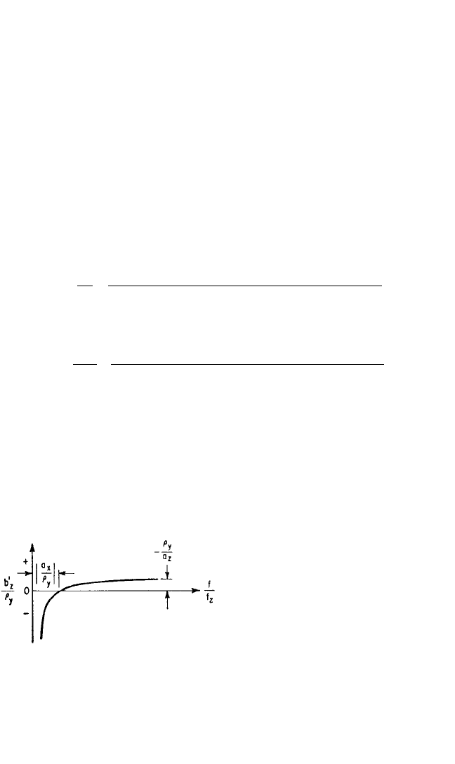
FIGURE 3.25 Curve showing the position of
the axis of pure rotation of the rigid body in Fig.
3.15 as a function of the frequency ratio f/f
z
when
the excitation is sinusoidal motion of the foun-
dation in the X direction [see Eq. (3.57)]. The
axis of rotation is parallel to the Y axis and in the
XZ plane, and its coordinate along the Z axis is
designated by b
z
′.
8434_Harris_03_b.qxd 09/20/2001 11:32 AM Page 3.43
of Eqs. (3.1) by setting x
b
= 0 (γ
0
motion is not considered). Substituting Eqs. (3.55)
and (3.56) for x
c 0
and β
0
, respectively, the axis of rotation is located at
= (3.57)
Figure 3.25 shows the relation of Eq. (3.57) graphically. At high values of frequency
f/f
z
, the axis does not change position significantly with frequency; b
z
′/ρ
y
approaches
a positive value as f/f
z
becomes large, since a
z
is negative (see Fig. 3.15).
When the resilient supporting elements have damping as well as elastic properties,
the solution of the equations of motion [see Eq. (3.31a)] becomes too laborious for
general use. Responses of systems with damping have been obtained for several typi-
cal cases using a digital computer. Figures 3.26 A, B, and C show the response at three
points in the body of the system shown in Fig. 3.15, with the excitation u = u
0
sin ωt.
The weight of the body is 45 lb; each of the four resilient supporting elements has
a stiffness k
z
= 1,050 lb/in. and stiffness ratios k
x
/k
z
= k
y
/k
z
=
1
⁄2. The critical damping
coefficients in the X, Y, Z directions are taken as c
cx
= 24
k
x
m
,c
cy
= 24
k
y
m
,c
cz
=
24
k
z
m
, respectively, where the expression for c
cz
follows fromthe single degree-
of-freedom case defined by Eq. (2.12). The fractions of critical damping are c
x
/c
cx
=
(a
x
/ρ
y
)
2
− (f/f
z
)
2
(a
z
/ρ
y
)(f/f
z
)
2
b
z
′
ρ
y
3.44 CHAPTER THREE
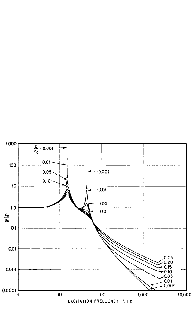
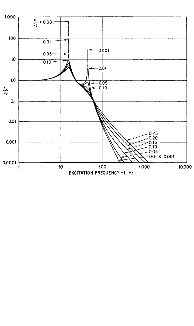
FIGURE 3.26A Response curves for point 1 with damping in the resilient supports in the system
shown in Fig. 3.15. The response is the ratio of the amplitude at point 1 of the rigid body in the X
direction to the amplitude of the foundation in the X direction (x
0
/u
0
). The fraction of critical
damping c/c
c
is the same in the X, Y, Z directions.
8434_Harris_03_b.qxd 09/20/2001 11:32 AM Page 3.44
c
y
/c
cy
= c
z
/c
cz
= c/c
c
, the parameter of the curves in Figs. 3.26A, B, and C. Coordinates
locating the resilient elements are a
x
=±5.25 in., a
y
=±3.50 in., and a
z
=−6.50 in. The
radii of gyration with respect to the X, Y, Z axes are ρ
x
= 4.40 in., ρ
y
= 5.10 in., and
ρ
z
= 4.60 in.
Natural frequencies calculated from Eqs. (3.37) and (3.40) are f
z
= 30.0 Hz;
f
xβ
= 43.7 Hz, 15.0 Hz; and f
yα
= 43.2 Hz, 11.7 Hz. The fraction of critical damping
c/c
c
varies between 0 and 0.25. Certain characteristic features of the response curves
in Figs. 3.26A, B, and C are:
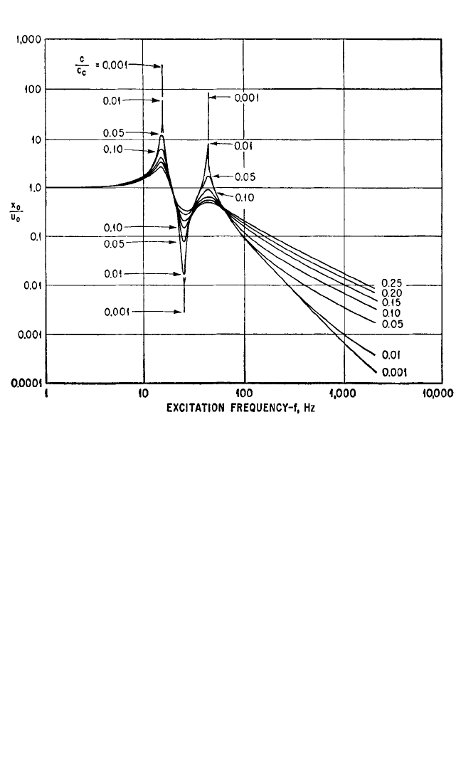
1. The relatively small response at the frequency of 24.2 Hz in Fig. 3.26C occurs
because point 3 lies near the axis of rotation of the rigid body at that frequency. Point 2
lies near the axis of rotation at higher frequencies, and the response becomes corre-
spondingly low, as shown in Fig. 3.26B. The position of the axis of rotation changes rap-
idly for small changes of frequency in the low- and intermediate-frequency range
(indicated by the sharp dip in the curves for small damping in Fig. 3.26C) and varies
asymptotically toward a final position as the forcing frequency increases (see Fig.
3.25).
2. The effect of damping on the magnitude of the response at the higher and
lower natural frequencies in coupled modes is illustrated. When the fraction of crit-
ical damping is between 0.01 and 0.10, the response at the lower of the coupled nat-
VIBRATION OF A RESILIENTLY SUPPORTED RIGID BODY 3.45
FIGURE 3.26B Response curves at point 2 in the system shown in Fig. 3.15. See caption for
Fig. 3.26A.
8434_Harris_03_b.qxd 09/20/2001 11:32 AM Page 3.45

ural frequencies is approximately 10 times as great as the response at the higher of
the coupled natural frequencies.With greater damping (c/c
c
≥ 0.15), the effect of res-
onance in the vicinity of the higher coupled natural frequency becomes so slight as
to be hardly discernible.
Two Planes of Symmetry with Resilient Supports Inclined in One Plane Only.
The system is shown in Fig. 3.21, and the excitation is u = u
0
sin ωt. The conditions of
symmetry are defined by Eqs. (3.33), (3.35), and (3.38). The response is entirely in
the x
c
, β coupled mode with the following amplitudes:
x
c0
=
2
−
cos
2
φ+sin
2
φ
2
u
0
4
− A
2
+
2
(3.58)
β
0
=
−
cos
2
φ+sin
2
φ
+
1 −
sin φ cos φ
2
u
0
/ρ
y
4
− A
2
+
2
where A is defined after Eq. (3.45). A similar set of expressions may be written for
the response in the y
c
, α coupled mode when the excitation is the motion v = v
0
sin ωt of the foundation:
y
c 0
=
sin
2
φ+cos
2
φ
2
−
2
v
0
4
− B
2
+
sin
2
φ+cos
2
φ
(3.59)
α
0
2
v
0
/ρ
x
=
4
− B
2
+
sin
2
φ+cos
2
φ
where B is defined after Eq. (3.46). No motion occurs in the z
c
or γ mode since the
quantities F
z
and M
z
are zero in Eqs. (3.31e) and (3.31f ).
Response curves for the system shown in Fig. 3.21 when damping is included are
qualitatively similar to those shown in Figs. 3.26.The significant advantage in the use
of inclined resilient supports is the additional versatility gained from the ability to
vary the angle of inclination φ, which directly affects the degree of coupling in the x
c
,
β coupled mode. For example, a change in the angle φ produces a change in the posi-
tion of the axis of pure rotation of the rigid body. In a manner similar to that used to
derive Eq. (3.57), Eqs. (3.58) yield the following expression defining the location of
the axis of rotation:
b
z
′
2
−
cos
2
φ+sin
2
φ
2
ρ
y
=
cos
2
φ+sin
2
φ
+
1 −
sin φ cos φ
2
(3.60)
f
f
r
a
x
ρ
y
k
p
k
r
a
z
ρ
y
k
p
k
r
f
f
r
k
p
k
r
a
x
ρ
y
k
p
k
r
a
y
ρ
x
k
p
k
r
k
q
k
r
f
f
r
f
f
r
f
f
r
a
z
ρ
x
k
q
k
r
a
y
ρ
x
k
p
k
r
k
q
k
r
f
f
r
f
f
r
f
f
r
k
q
k
r
a
y
ρ
x
k
p
k
r
k
q
k
r
a
x
ρ
y
k
p
k
r
f
f
r
f
f
r
f
f
r
a
x
ρ
y
k
p
k
r
a
z
ρ
y
k
p
k
r
a
x
ρ
y
k
p
k
r
f
f
r
f
f
r
f
f
r
k
p
k
r
a
x
ρ
y
k
p
k
r
3.46 CHAPTER THREE
8434_Harris_03_b.qxd 09/20/2001 11:32 AM Page 3.46
BODY-INDUCED SINUSOIDAL VIBRATION
This section includes the analysis of a resiliently supported rigid body wherein the
excitation consists of forces and moments applied directly to the rigid body (or orig-
inating within the body). The system has two planes of symmetry with orthogonal
resilient supports; the modal coupling and natural frequencies for such a system are
considered above. Two types of excitation are considered: (1) a force rotating about
an axis parallel to one of the principal inertial axes and (2) an oscillatory moment
acting about one of the principal inertial axes. There is no motion of the foundation
that supports the resilient elements; thus, the following terms in Eqs. (3.31) are equal
to zero:
u = v = w = a = b = g = 0 (3.61)
Two Planes of Symmetry with Orthogonal Resilient Elements Excited by a
Rotating Force. The system excited by the rotating force is illustrated in Fig. 3.27.
The force F
0
rotates at frequency ω about an axis parallel to the Y axis but spaced
therefrom by the coordinate distances d
x
,d
z
; the force is in the XZ plane.The forces
and moments applied to the body by the rotating force F
0
are
VIBRATION OF A RESILIENTLY SUPPORTED RIGID BODY 3.47
FIGURE 3.26C Response curves at point 3 in the system shown in Fig. 3.15. See caption for
Fig. 3.26A.
8434_Harris_03_b.qxd 09/20/2001 11:32 AM Page 3.47

F
x
= F
0
cos ωtM
x
= 0
F
y
= 0 M
y
= F
0
(d
z
cos ωt − d
x
sin ωt) (3.62)
F
z
= F
0
sin ωtM
z
= 0
The conditions of symmetry are defined by Eqs. (3.33), (3.34), (3.35), and (3.38); and
the excitation is defined by Eqs. (3.61) and (3.62). Substituting these conditions into
the equations of motion, Eqs. (3.31) show that vibration response is not excited in the
coupled y
c
, α mode or in the γ mode. In the Z direction, the motion z
c 0
of the body
and the force F
tz
transmitted through the resilient elements can be found from Eq.
(2.30) and Fig. 2.17 since single degree-of-freedom behavior is involved. The hori-
zontal displacement amplitude x
c 0
of the center-of-gravity in the X direction and the
rotational displacement amplitude β
0
about the Y axis are given by
x
c 0
k
x
−
+
2
−
2
2
+
2
F
0
/4k
x
=
k
z
4
−
+
2
+
2
2
+
2
(3.63)
β
0
k
x
−
+
2
2
+
−
2
F
0
/4k
x
ρ
y
=
k
z
4
−
+
2
+
2
2
+
2
a
x
ρ
y
k
x
k
z
f
f
z
a
x
ρ
y
a
z
ρ
y
k
x
k
z
k
x
k
z
f
f
z
f
2
f
z
2
k
x
k
z
d
x
ρ
y
f
f
z
d
z
ρ
y
d
z
ρ
y
a
z
ρ
y
k
x
k
z
a
x
ρ
y
k
x
k
z
f
f
z
a
x
ρ
y
a
z
ρ
y
k
x
k
z
k
x
k
z
f
f
z
a
z
ρ
y
d
x
ρ
y
k
x
k
z
f
f
z
a
x
ρ
y
d
z
ρ
y
a
z
ρ
y
a
z
ρ
y
k
x
k
z
3.48 CHAPTER THREE
FIGURE 3.27 Example of a rigid body on orthogonal resilient supports with
two planes of symmetry, excited by body-induced sinusoidal excitation. Alter-
native excitations are (1) the force F
0
in the XZ plane rotating with angular
velocity ωt about an axis parallel to the Y axis and (2) the oscillatory moment
M
0
sin ωt acting about the Y axis.There is no motion of the foundation that sup-
ports the resilient elements.
8434_Harris_03_b.qxd 09/20/2001 11:32 AM Page 3.48

where a
x
,a
z
are location coordinates of the resilient supports, and
f
z
=
(3.64)
The amplitude of the oscillating force F
tx
in the X direction and the amplitude of the
oscillating moment M
ty
about the Y axis which are transmitted to the foundation by
the combination of resilient elements are
F
tx
= 4k
x
x
c 0
2
− 2a
z
x
c 0
β
0
cos (φ
x
−φ
β
) + a
z
2
β
0
2
(3.65)
M
ty
= 4k
z
a
x
2
β
0
where F
tx
is the sum of the forces transmitted by the individual resilient elements
and M
ty
is a moment formed by forces in the Z direction of opposite sign at opposite
resilient supports. The angles φ
x
and φ
β
are defined by
tan φ
x
=
−
+
2
−
2
[0°≤φ
x
≤ 360°]
tan φ
β
=
−
+
2
[0°≤φ
β
≤ 360°]
−
2
To obtain the correct value of (φ
x
−φ
β
) in Eq. (3.65), the signs of the numerator and
denominator in each tangent term must be inspected to determine the proper quad-
rant for φ
x
and φ
β
.
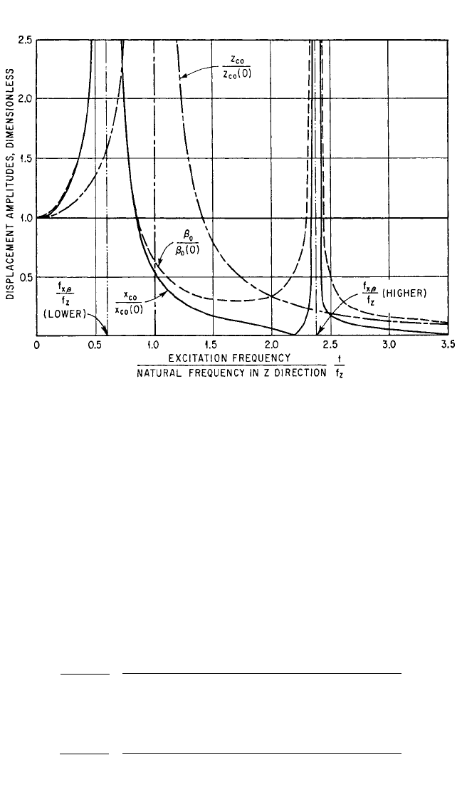
Example 3.2. Consider an electric motor which has an unbalanced rotor, creat-
ing a centrifugal force. The motor weighs 3,750 lb, and has a radius of gyration ρ
y
=
9.10 in.The distances d
x
= d
y
= d
z
= 0, that is, the axis of rotation is the Y principal axis
and the center-of-gravity of the rotor is in the XZ plane. The resilient supports each
have a stiffness ratio of k
x
/k
z
= 1.16, and are located at a
z
=−14.75 in., a
x
=±12.00 in.
The resulting displacement amplitudes of the center-of-gravity, expressed dimen-
sionlessly, are shown in Fig. 3.28; the force and moment amplitudes transmitted to
the foundation, expressed dimensionlessly, are shown in Fig. 3.29.The displacements
of the center-of-gravity of the body are dimensionalized with respect to the dis-
placements at zero frequency:
z
c 0
(0) =
x
c 0
(0) =
1 +
2
(3.66)
β
0
(0) =
2
At excitation frequencies greater than the higher natural frequency of the x
c
, β cou-
pled motion, the displacements, forces, and moment all continuously decrease as the
frequency increases.
a
z
a
x
F
0
4k
z
a
z
a
z
a
x
k
x
k
z
F
0
4k
x
F
0
4k
z
f
f
z
k
x
k
z
d
x
ρ
y
f
f
z
d
z
ρ
y
d
z
ρ
y
a
z
ρ
y
k
x
k
z
d
x
ρ
y
a
z
ρ
y
k
x
k
z
f
f
z
a
x
ρ
y
d
z
ρ
y
a
z
ρ
y
a
z
ρ
y
k
x
k
z
4k
z
m
1
2π
VIBRATION OF A RESILIENTLY SUPPORTED RIGID BODY 3.49
8434_Harris_03_b.qxd 09/20/2001 11:32 AM Page 3.49
Two Planes of Symmetry with Orthogonal Resilient Elements Excited by an
Oscillating Moment. Consider the oscillatory moment M
0
acting about the Y axis
with forcing frequency ω. The resulting applied forces and moments acting on the
body are
M
y
= M
0
sin ωt
F
x
= F
y
= F
z
= M
x
= M
z
= 0
(3.67)
Substituting conditions of symmetry defined by Eqs. (3.33), (3.34), (3.35), and (3.38),
and the excitation defined by Eqs. (3.61) and (3.67), the equations of motion [Eqs.
(3.31)] show that oscillations are excited only in the x
c
, β coupled mode. Solving for
the resulting displacements,
x
c 0
2
M
0
/4k
x
ρ
y
=
4
−
+
2
+
2
2
+
2
(3.68)
β
0
−
2
M
0
/4k
x
ρ
y
2
=
4
−
+
2
+
2
2
+
2
a
x
ρ
y
k
x
k
z
f
f
z
a
x
ρ
y
a
z
ρ
y
k
x
k
z
k
x
k
z
f
f
z
f
f
z
k
x
k
z
k
x
k
z
a
x
ρ
y
k
x
k
z
f
f
z
a
x
ρ
y
a
z
ρ
y
k
x
k
z
k
x
k
z
f
f
z
a
z
ρ
y
k
x
k
z
3.50 CHAPTER THREE
FIGURE 3.28 Response curves for the system shown in Fig. 3.27 when excited by a rotating force
F
0
acting about the Y axis. The parameters of the system are k
x
/k
z
= 1.16, a
x
/ρ
y
=±1.32, a
z
/ρ
y
=−1.62.
Only x
c
,z
c
, β displacements of the body are excited [see Eqs. (3.63)].The displacements are expressed
dimensionlessly by employing the displacements at zero frequency [see Eqs. (3.66)].
8434_Harris_03_b.qxd 09/20/2001 11:32 AM Page 3.50