Harris C.M., Piersol A.G. Harris Shock and vibration handbook
Подождите немного. Документ загружается.

RIGID-ROTOR BALANCING—STATIC UNBALANCE
Rigid-rotor balancing is important because it comprises the majority of the balanc-
ing work done in industry. By far the greatest number of rotors manufactured and
installed in equipment can be classified as “rigid” by definition. All balancing
machines are designed to perform rigid-rotor balancing.*
Consider the case in which the shaft axis is not coincident with the principal axis,
as illustrated in Fig. 39.3. In practice, with even the closest manufacturing tolerances,
the journals are never concentric with
the principal axis of the rotor. If concen-
tric rigid bearings are placed around the
journals, thus forcing the rotor to turn
about the connecting line between the
journals, i.e., the shaft axis, a variable
force is sensed at each bearing.
The center-of-gravity is located on
the principal axis, and is not on the axis
of rotation (shaft axis). From this it fol-
lows that there is a net radial force act-
ing on the rotor which is due to centrifugal acceleration.The magnitude of this force
is given by
F = mω
2
(39.1)
PERFECT BALANCE
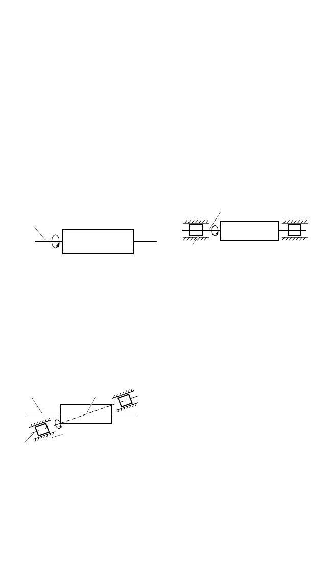
Consider a rigid body which is rotating at a uniform speed about one of its three
principal inertia axes. Suppose that the forces which cause the rotation and support
the body are neglected; then it will rotate about this axis without wobbling, i.e., the
principal axis (which is fixed in the body) coincides with a line fixed in space (Fig.
39.1). Now construct circular, concentric journals around the axis at the points where
the axis protrudes from the body, i.e., on the stub shafts whose axes coincide with the
principal axis. Since the axis does not wobble, the newly constructed journals also
will not wobble. Next, place the journals in bearings which are circular and concen-
tric to the principal axis (Fig. 39.2). It is assumed that there is no dynamic action of
the elasticity of the rotor and the lubricant in the bearings. A rigid rotor constructed
and supported in this manner will not wobble; the bearings will exert no forces other
than those necessary to support the weight of the rotor. In this assembly, the radial
distance between the center-of-gravity of the rotor and the shaft axis (i.e., a straight
line connecting the journal axes) is zero. The principal axis and the shaft axis coin-
cide. This rotor is said to be perfectly balanced.
39.2 CHAPTER THIRTY-NINE, PART I
PRINCIPAL AXIS
FIGURE 39.1 Rigid body rotating about prin-
cipal axis.
PRINCIPAL AXIS
BEARING
JOURNAL
FIGURE 39.2 Balanced rigid rotor.
PRINCIPAL AXIS
c.g.
BEARING
AXIS OF ROTATION (JOURNAL AXIS)
FIGURE 39.3 Unbalanced rigid rotor.
* Field balancing equipment is specifically excluded from this category since it is designed for use with
both rigid and flexible rotors.
8434_Harris_39_b.qxd 09/20/2001 12:24 PM Page 39.2

where m is the mass of the rotor, is the eccentricity or radial distance of the center-
of-gravity from the axis of rotation, and ω is the rotational speed in radians per sec-
ond. Since the rotor is assumed to be rigid and thus not capable of distortion, this
force is balanced by two reaction forces. There is one force at each bearing. Their
algebraic sum is equal in magnitude and opposite in sense. The relative magnitudes
of the two forces depend, in part, upon the axial position of each bearing with
respect to the center-of-gravity of the rotor. In simplified form, this illustrates the
“balancing problem.” One must choose a practical method of constructing a per-
fectly balanced rotor from this unbalanced rotor.
The center-of-gravity may be moved to the shaft axis (or as close to this axis as is
practical) in one of two ways.The journals may be modified so that the shaft axis and
an axis through the center-of-gravity are moved to essential coincidence. From the-
oretical considerations, this is a valid method of minimizing unbalance caused by the
displacement of the center-of-gravity from the shaft axis, but for practical reasons it
is difficult to accomplish. Instead, it is easier to achieve a radial shift of the center-of-
gravity by adding mass to or subtracting it from the mass of the rotor; this change in
mass takes place in the longitudinal plane which includes the shaft axis and the cen-
ter-of-gravity. From Eq. (39.1), it follows that there can be no net radial force acting
on the rotor at any speed of rotation if
m′r = m (39.2)
where m′ is the mass added to or subtracted from that of the rotor and r is the radial
distance to m′. There may be a couple, but there is no net force. Correspondingly,
there can be no net bearing reaction. Any residual reactions sensed at the bearings
would be due solely to the couple acting on the rotor.
If this rotor-bearing assembly were supported on a scale having a sufficiently
rapid response to sense the change in force at the speed of rotation of the rotor, no
fluctuations in the magnitude of the force would be observed. The scale would reg-
ister only the dead weight of the rotor-bearing assembly.
This process of effecting essential coincidence between the center-of-gravity of the
rotor and the shaft axis is called “single-plane (static) balancing.” The latter name for
the process is more descriptive of the end result than of the procedure that is followed.
If a rotor which is supported on two bearings has been balanced statically, the
rotor will not rotate under the influence of gravity alone. It can be rotated to any
position and, if left there, will remain in that position. However, if the rotor has not
been balanced statically, then from any position in which the rotor is initially placed,
it will tend to turn to that position in which the center-of-gravity is lowest.
As indicated below, single-plane balancing can be accomplished most simply (but
not necessarily with great accuracy) by supporting the rotor on flat, horizontal ways
and allowing the center-of-gravity to seek its lowest position. It also can be accom-
plished in a centrifugal balancing machine by sensing and correcting for the unbal-
ance force characterized by Eq. (39.1).
RIGID-ROTOR BALANCING—DYNAMIC UNBALANCE
When a rotor is balanced statically, the shaft axis and principal inertia axis may not
coincide; single-plane balancing ensures that the axes have only one common point,
namely, the center-of-gravity.Thus, perfect balance is not achieved. To obtain perfect
balance, the principal axis must be rotated about the center-of-gravity in the longi-
tudinal plane characterized by the shaft axis and the principal axis. This rotation can
BALANCING OF ROTATING MACHINERY 39.3
8434_Harris_39_b.qxd 09/20/2001 12:24 PM Page 39.3
be accomplished by modifying the journals (but, as before, this is impractical) or by
adding masses to or subtracting them from the mass of the rotor in the longitudinal
plane characterized by the shaft axis and the principal inertia axis. Although adding
or subtracting a single mass may cause rotation of the principal axis relative to the
shaft axis, it also disturbs the static balance already achieved. From this it can be
deduced that a couple must be applied to the rotor in the longitudinal plane. This is
usually accomplished by adding or subtracting two masses of equal magnitude, one
on each side of the principal axis (so as not to disturb the static balance) and one in
each of two radial planes (so as to produce the necessary rotatory effect). Theoreti-
cally, it is not important which two radial planes are selected since the same rotatory
effect can be achieved with appropriate masses, irrespective of the axial location of
the two planes. Practically, the choice of suitable planes may be important. Usually,
it is best to select planes which are separated axially by as great a distance as possi-
ble in order to minimize the magnitude of the masses required.
The above process of bringing the principal inertial axis of the rotor into essential
coincidence with the shaft axis is called “two-plane (dynamic) balancing.” If a rotor is
balanced in two planes, then, by definition, it is balanced statically; however, the con-
verse is not true.
FLEXIBLE-ROTOR BALANCING
1
If the bearing supports are rigid, then the forces exerted on the bearings are due
entirely to centrifugal forces caused by the unbalance. Dynamic action of the elas-
ticity of the rotor and the lubricant in the bearings has been ignored.
The portion of the overall problem in which the dynamic action and interaction
of rotor elasticity, bearing elasticity, and damping are considered is called flexible
rotor or modal balancing.
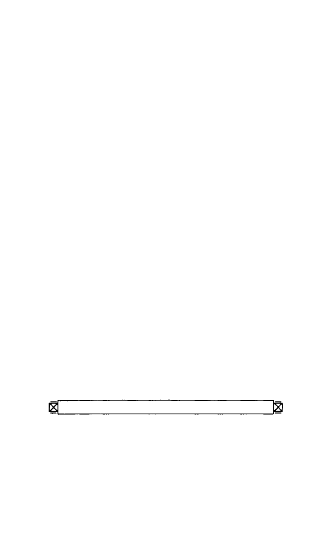
Critical Speed. Consider a long, slender rotor, as shown in Fig. 39.4. It represents
the idealized form of a typical flexible rotor, such as a paper machinery roll or tur-
bogenerator rotor. Assume further that all unbalances occurring along the rotor
caused by machining tolerances, inhomogeneities of material, etc. are compensated
by correction weights placed in the end faces of the rotor, and that the balancing is
done at a low speed as if the rotor were a rigid body.
Assume there is no damping in the rotor or its bearing supports. Consider a thin
slice of this rotor perpendicular to the shaft axis (see Fig. 39.5A). This axis intersects
the slice at its geometric center E when the rotor is not rotating, provided that
deflection due to gravity forces is ignored. The center-of-gravity of the slice is dis-
placed by δ from E due to an unbalance in the slice (caused by machining tolerances,
inhomogeneity, etc., mentioned above) which was compensated by correction
weights in the rotor’s end planes. If the rotor starts to rotate about the shaft axis with
an angular speed ω, then the slice starts to rotate in its own plane at the same speed
about an axis through E. Centrifugal force mδω
2
is thus experienced by the slice.This
force occurs in a direction perpendicular to the shaft axis and may be accompanied
39.4 CHAPTER THIRTY-NINE, PART I
FIGURE 39.4 Idealized flexible rotor.
8434_Harris_39_b.qxd 09/20/2001 12:24 PM Page 39.4
by similarly caused forces at other cross sections along the rotor; such forces are
likely to vary in magnitude and direction.They cause the rotor to bend, which in turn
causes additional centrifugal forces and further bending of the rotor.
At every speed ω, equilibrium conditions require that for one slice, the centrifu-
gal and restoring forces be related by
m(δ+x)ω
2
= kx (39.3)
where x is the deflection of the shaft (the radial distance between the geometric cen-
ter and the shaft axis) and k is the shaft stiffness (Fig. 39.5B). In Fig. 39.5, the cen-
trifugal and restoring forces are plotted for various speeds (ω
1
<ω
2
<ω
3
<ω
4
<ω
5
).
The point of intersection of the lines representing the two forces denotes the equi-
librium condition for the rotor at the given speeds. For this ideal example, as the
speed increases, the point which denotes equilibrium will move outward until, at say
ω
3
, a speed is reached at which there is no resulting force and the lines are parallel.
Since equilibrium is not possible at this speed, it is called the critical speed. The crit-
ical speed ω
n
of a rotating system corresponds to a resonant frequency of the system.
At speeds greater than ω
3
(ω
n
), the lines representing the centrifugal and
restoring forces again intersect. As ω increases, the slope of the line mω
2
(x +δ)
increases correspondingly until, for speeds which are large, the deflection x
approaches the value of δ, i.e., the rotor tends to rotate about its center-of-gravity.
BALANCING OF ROTATING MACHINERY 39.5
FIGURE 39.5 Rotor behavior below, at, and above first critical speed.
8434_Harris_39_b.qxd 09/20/2001 12:24 PM Page 39.5

Unbalance Distribution. Apart from any special and obvious design features, the
axial distribution of unbalance in the slices previously examined along any rotor is
likely to be random.The distribution may be significantly influenced by the presence
of large local unbalances arising from shrink-fitted discs, couplings, etc. The rotor
may also have a substantial amount of initial bend, which may produce effects simi-
lar to those due to unbalance.The method of construction can influence significantly
the magnitude and distribution of unbalance along a rotor. Rotors may be machined
from a single forging, or they may be constructed by fitting several components
together. For example, jet-engine rotors are constructed by joining many shell and
disc components, whereas paper mill rolls are usually manufactured from a single
piece of material.
The unbalance distributions along two nominally identical rotors may be similar
but rarely identical.
Contrary to the case of a rigid rotor, distribution of unbalance is significant in a
flexible rotor because it determines the degree to which any bending or flexural
mode of vibration is excited. The resulting modal shapes are reduced to acceptable
levels by flexible-rotor balancing, also called “modal balancing.”*
Response of a Flexible Rotor to Unbalance. In common with all vibrating sys-
tems, rotor vibration is the sum of its modal components. For an undamped flexible
rotor which rotates in flexible bearings, the flexural modes coincide with principal
modes and are plane curves rotating about the axis of the bearing. For a damped
flexible rotor, the flexural modes may be space (three-dimensional) curves rotating
about the axis of the bearings. The damping forces also limit the flexural amplitudes
at each critical speed. In many cases, however, the damped modes can be treated
approximately as principal modes and hence regarded as rotating plane curves.
The unbalance distribution along a rotor may be expressed in terms of modal
components.The vibration in each mode is caused by the corresponding modal com-
ponent of unbalance. Moreover, the response of the rotor in the vicinity of a critical
speed is usually predominantly in the associated mode. The rotor modal response is
a maximum at any rotor critical speed corresponding to that mode. Thus, when a
rotor rotates at a speed near a critical speed, it is disposed to adopt a deflection
shape corresponding to the mode associated with this critical speed. The degree to
which large amplitudes of rotor deflection occur in these circumstances is deter-
mined by the modal component of unbalance and the amount of damping present in
the rotor system.
If the modal component of unbalance is reduced by a number of discrete correc-
tion masses, then the corresponding modal component of vibration is similarly
reduced.The reduction of the modal components of unbalance in this way forms the
basis of the modal balancing technique.
Flexible-Rotor Mode Shapes. The stiffnesses of a rotor, its bearings, and the
bearing supports affect critical speeds and therefore mode shapes in a complex man-
ner. For example, Fig. 39.6 shows the effect of varying bearing and support stiffness
relative to that of the rotor.The term “soft” or “hard” bearing is a relative one, since
for different rotors the same bearing may appear to be either soft or hard. The
schematic diagrams of the figure illustrate that the first critical speed of a rotor sup-
ported in a balancing machine having soft-spring-bearing supports occurs at a lower
frequency and in an apparently different shape than that of the same rotor sup-
39.6 CHAPTER THIRTY-NINE, PART I
* All modal balancing is accomplished by multiplane corrections; however, multiplane balancing need not
be modal balancing, since multiplane balancing refers only to unbalance correction in more than two planes.
8434_Harris_39_b.qxd 09/20/2001 12:24 PM Page 39.6
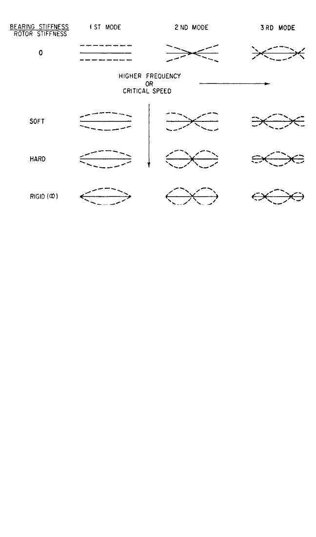
ported in a hard-bearing balancing machine where the bearing support stiffness
approximates service conditions.
To evaluate whether a given rotor may require a flexible-rotor balancing proce-
dure, the following rotor characteristics must be considered:
1. Rotor configuration and service speed.
2. Rotor design and manufacturing procedures. Rotors which are known to be flex-
ible or unstable may still be capable of being balanced as rigid rotors.
Rotor Elasticity Test. This test is designed to determine if a rotor can be consid-
ered rigid for balancing purposes or if it must be treated as flexible. The test is car-
ried out at service speed either under service conditions or in a high-speed,
hard-bearing balancing machine whose support-bearing stiffness closely approxi-
mates that of the final supporting system. The rotor should first be balanced. A
weight is then added in each end plane of the rotor near its journals; the two weights
must be in the same angular position. During a subsequent test run, the vibration is
measured at both bearings. Next, the rotor is stopped and the test weights are moved
to the center of the rotor, or to a position where they are expected to cause the
largest rotor distortion; in another run the vibration is again measured at the bear-
ings. If the total of the first readings is designated x, and the total of the second read-
ings y, then the ratio (y − x)/x should not exceed 0.2. Experience has shown that if
this ratio is below 0.2, the rotor can be corrected satisfactorily at low speed by apply-
ing correction weights in two or three selected planes. Should the ratio exceed 0.2,
the rotor usually must be checked at or near its service speed and corrected by a
modal balancing technique.
High-Speed Balancing Machines. Any technique of modal balancing requires a
balancing machine having a variable balancing speed with a maximum speed at least
equal to the maximum service speed of the flexible rotor. Such a machine must also
BALANCING OF ROTATING MACHINERY 39.7
FIGURE 39.6 Effect of ratio of bearing stiffness to rotor stiffness on mode shape at critical
speeds.
8434_Harris_39_b.qxd 09/20/2001 12:24 PM Page 39.7

have a drive-system power rating which takes into consideration not only accelera-
tion of the rotor inertia but also windage losses and the energy required for a rotor
to pass through a critical speed. For some rotors, windage is the major loss; such
rotors may have to be run in vacuum chambers to reduce the fanlike action of the
rotor and to prevent the rotor from becoming excessively hot. For high-speed bal-
ancing installations, appropriate controls and safety measures must be employed to
protect the operator, the equipment, and the surrounding work areas.
Flexible-Rotor Balancing Techniques. Flexible-rotor balancing consists essen-
tially of a series of individual balancing operations performed at successively greater
rotor speeds:
At a low speed, where the rotor is considered rigid. (Low-speed balancing of flex-
ible rotors usually is performed only in a balancing machine.)
At a speed where significant rotor deformation occurs in the mode of the first
flexural critical speed. (This deformation may occur at speeds well below the crit-
ical speed.)
At a speed where significant rotor deformation occurs in the mode of the second
flexural critical speed. (This applies only to rotors with a maximum service speed
affected significantly by the mode shape of the second flexural critical speed.)
At a speed where significant rotor deformation occurs in the mode of the third
critical speed, etc.
At the maximum service speed of the rotor.
The balancing of flexible rotors requires experience in determining the size of
correction weights when the rotor runs in a flexible mode. The process is consider-
ably more complex than standard low-speed balancing techniques used with rigid
rotors. Primarily this is due to a shift of mass within the rotor (as the speed of rota-
tion changes), caused by shaft and/or body elasticity, asymmetric stiffness, thermal
dissymmetry, incorrect centering of rotor mass and shifting of windings and associ-
ated components, and fit tolerances and couplings.
Before starting the modal balancing procedure, the rotor temperature should be
stabilized in the lower- or middle-speed range until unbalance readings are repeat-
able. This preliminary warmup may take from a few minutes to several hours
depending on the type of rotor, its dimensions, its mass, and its pretest condition.
Once the rotor is temperature-stabilized, the balancing process can begin. Sev-
eral weight corrections in both end planes and along the rotor surface are required.
In the commonly practiced, comprehensive modal balancing technique, unbalance
correction is performed in several discrete modes, each mode being associated with
the speed range in which the rotor is deformed to the mode shape corresponding to
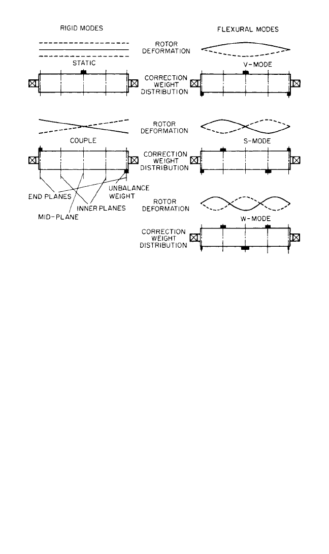
a particular flexural critical speed. Figure 39.7 shows a rotor deformed in five of the
mode shapes of Fig. 39.6; the location of the weights which provide the proper cor-
rection for these mode shapes is indicated.
First, the rotor is rotated at a speed less than one-half the rotor’s first flexural crit-
ical speed and balanced using a rigid-rotor balancing technique. Balancing correc-
tions are performed at the end planes to reduce the original amount of unbalance to
three or four times the final balance tolerance.
Correction for the First Flexural Mode (V Mode). The balancing speed is
increased until rotor deformation occurs, accompanied by a rapid increase in unbal-
ance indication at the same angular position for both end planes. Unbalance correc-
tions for this mode are made in at least three planes. Due to the bending of the rotor,
39.8 CHAPTER THIRTY-NINE, PART I
8434_Harris_39_b.qxd 09/20/2001 12:24 PM Page 39.8
the unbalance indication is not directly proportional to the correction to be applied.
A new relationship between unbalance indication and corresponding correction
weight must be established by test with trial weights. A weight is first added in the
correction plane nearest the middle of the rotor. For large turbo-generator rotors
such a trial weight should be in the range of 30 to 60 oz-in./ton of rotor weight. Two
additional corrections are added in the end planes diametrically opposite to the cen-
ter weight, each equal to one-half the magnitude of the center weight. This process
may have to be repeated a number of times, each run reducing the magnitude of the
weight applications until the residual unbalance is approximately 1 to 3 oz-in./ton of
turbo-generator rotor weight. Then the speed is increased slowly to the maximum
service speed; at the same time, the unbalance indicator is monitored. If an excessive
unbalance indication is observed as the rotor passes through its first critical speed,
further unbalance corrections are required in the V mode until the maximum ser-
vice speed can be reached without an excessive unbalance indication. If a second
flexural critical speed is observed before the maximum service speed is reached, the
additional balancing operation in the S mode must be performed, as indicated
below.
Correction for the Second Flexural Mode (S Mode). The rotor speed is
increased until significant rotor deformation due to the second flexural mode is
observed. This is indicated by a rapid increase in unbalance indication measured in
the end planes at angular positions opposite to each other. Unbalance corrections
for this S mode are made in at least four planes, as indicated in Fig. 39.7. The weights
placed in the end correction planes must be diametrically opposed; on the idealized
symmetrical rotor, each end-plane weight must be equal to one-half the correction
weight placed in one of the inner planes. Of primary concern is that the S-mode
weight set not have any influence on the previously corrected mode shape. The cor-
BALANCING OF ROTATING MACHINERY 39.9
FIGURE 39.7 Rotor mode shapes and correction weights.
8434_Harris_39_b.qxd 09/20/2001 12:24 PM Page 39.9

rection weight in each inner plane must be diametrically opposed to its nearest end-
plane correction weight. The procedure to determine the relationship between
unbalance indication and required correction weight is similar to that used in the
V-mode procedure, described above. The S-mode balancing process must be
repeated until an acceptable residual unbalance is achieved. If a third critical speed
is observed before the maximum service speed is reached, the additional balancing
operation in the W mode must be performed, as indicated below.
Corrections for the Third Flexural Mode (W Mode). The rotor speed is
increased further until significant rotor deformation due to the third flexural mode
is observed. Corrections are made in the rotor with a five-weight set (shown in Fig.
39.7) and in a manner similar to that used in correcting for the first and second flex-
ural modes.
If the service-speed range requires it, higher modes (those associated with the nth
critical speed, for example) may have to be corrected as well. For each of these
higher modes, a set of (n + 2) correction weights is required.
Final Balancing at Service Speed. Final balancing takes place with the rotor at
its service speed. Correction should be made only in the end planes.The final balance
tolerance for large turbo-generators, for example, will normally be on the order of 1
oz-in./ton of rotor weight. If the rotor cannot be brought into proper balance toler-
ances, the S-mode, V-mode, and W-mode corrections may require slight adjustment.
To achieve repeatability of the correction effects, the same balancing speed for
each mode must be accurately maintained. Depending on the size of the rotor, the
number of modes that must be corrected, and the ease with which weights can be
applied, the entire process may take anywhere from 3 to 30 hours.
The relative position of the unbalance correction planes shown in Fig. 39.7
applies to symmetrical rotors only. Rotors with axial asymmetry generally require
unsymmetrically spaced correction planes. In the case of assembled rotors which
may “take a set” at or near service speed (e.g., shrunk-on turbine stages find their
final position), only preliminary unbalance corrections are made at lower speeds
to enable the rotor to be accelerated to service or overspeed, the latter being usu-
ally 20 percent above maximum service speed. Since the “set” creates new unbal-
ance, the normal balancing procedure is commenced only after the initial
high-speed run.
Computer programs are available which facilitate the selection of the most
appropriate correction planes and the computation of correction weights by the
influence coefficient method. Other flexible-rotor balancing techniques rely
mostly on experience data available from previously manufactured rotors of the
same type, or correct only for flexural modes if no low-speed balancing equipment is
available.
SOURCES OF UNBALANCE
Sources of unbalance in rotating machinery may be classified as resulting from
1. Dissymmetry (core shifts in castings, rough surfaces on forgings, unsymmetrical
configurations)
2. Nonhomogeneous material (blowholes in cast rotors, inclusions in rolled or
forged materials, slag inclusions or variations in crystalline structure caused by
variations in the density of the material)
3. Distortion at service speed (blower blades in built-up designs)
39.10 CHAPTER THIRTY-NINE, PART I
8434_Harris_39_b.qxd 09/20/2001 12:24 PM Page 39.10

4. Eccentricity (journals not concentric or circular, matching holes in built-up
rotors not circular)
5. Misalignment of bearings
6. Shifting of parts due to plastic deformation of rotor parts (windings in electric
armatures)
7. Hydraulic or aerodynamic unbalance (cavitation or turbulence)
8. Thermal gradients (steam-turbine rotors, hollow rotors such as paper mill rolls)
Often, balancing problems can be minimized by careful design in which unbal-
ance is controlled. When a part is to be balanced, large amounts of unbalance
require large corrections. If such corrections are made by removal of material, addi-
tional cost is involved and part strength may be affected. If corrections are made by
addition of material, cost is again a factor and space requirements for the added
material may be a problem.
Manufacturing processes are a major source of unbalance. Unmachined portions
of castings or forgings which cannot be made concentric and symmetrical with
respect to the shaft axis introduce substantial unbalance. Manufacturing tolerances
and processes which permit any eccentricity or lack of squareness with respect to the
shaft axis are sources of unbalance.Tolerances necessary for economical assembly of
several elements of a rotor permit radial displacement of parts of the assembly and
thereby introduce unbalance.
Limitations imposed by design often introduce unbalance effects which cannot
be corrected adequately by refinement in design. For example, electrical design lim-
itations impose a requirement that one coil be at a greater radius than the others in
a certain type of electric armature. It is impractical to design a compensating unbal-
ance into the armature.
Fabricated parts, such as fans, often distort nonsymmetrically under service con-
ditions. Design and economic considerations prevent the adaptation of methods
which might eliminate this distortion and thereby reduce the resulting unbalance.
Ideally, rotating parts always should be designed for inherent balance, whether a
balancing operation is to be performed or not. Where low service speeds are
involved and the effects of a reasonable amount of unbalance can be tolerated, this
practice may eliminate the need for balancing. In parts which require unbalanced
masses for functional reasons, these masses often can be counterbalanced by design-
ing for symmetry about the shaft axis.
MOTIONS OF UNBALANCED ROTORS
In Fig. 39.8 a rotor is shown spinning freely in space. This corresponds to spinning
above resonance in soft bearings. In Fig. 39.8A only static unbalance is present and
the center line of the shaft sweeps out a cylindrical surface. Figure 39.8B illustrates
the motion when only couple unbalance is present. In this case, the center line of the
rotor shaft sweeps out two cones which have their apexes at the center-of-gravity of
the rotor. The effect of combining these two types of unbalance when they occur in
the same axial plane is to move the apex of the cones away from the center-of-
gravity. In most cases, there will be no apex and the shaft will move in a more com-
plex combination of the motions shown in Fig. 39.8. Such a condition comes about
through a random combination of static and couple unbalance called dynamic
unbalance.
BALANCING OF ROTATING MACHINERY 39.11
8434_Harris_39_b.qxd 09/20/2001 12:24 PM Page 39.11