Harris C.M., Piersol A.G. Harris Shock and vibration handbook
Подождите немного. Документ загружается.

OPERATING PRINCIPLES OF BALANCING
MACHINES
2,3
This section describes the basic operating principles and general features of the var-
ious types of balancing machines which are available commercially.With this type of
information, it is possible to determine the basic type of machine required for a
given application.
Every balancing machine must determine by some technique both the magnitude
of a correction weight and its angular position in each of one, two, or more selected
balancing planes. For single-plane balancing this can be done statically, but for two-
or multiplane balancing it can be done only while the rotor is spinning. Finally, all
machines must be able to resolve the unbalance readings, usually taken at the bear-
ings, into equivalent corrections in each of the balancing planes.
On the basis of their method of operation, balancing machines and equipment
can be grouped in two general categories:
1. Gravity balancing equipment
2. Centrifugal balancing machines and field balancing equipment
In the first category, advantage is taken of the fact that a body that is free to rotate
always seeks that position in which its center-of-gravity is lowest. Gravity balancing
equipment, also called nonrotating balancers, includes horizontal ways, knife-edges
or roller arrangements, spirit-level devices (“bubble balancers”), and vertical pen-
dulum types. All are capable of detecting and/or indicating only static unbalance.
In the second category, the amplitude and phase of motions or reaction forces
caused by once-per-revolution centrifugal forces resulting from unbalance are
sensed, measured, and indicated by appropriate means. Field balancing equipment
provides sensing and measuring instrumentation only; the necessary measurements
for balancing a rotor are taken while the rotor runs in its own bearings and under
39.12 CHAPTER THIRTY-NINE, PART I
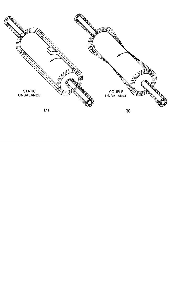
FIGURE 39.8 Effect of static and couple unbalance on free rotor motion.
8434_Harris_39_b.qxd 09/20/2001 12:24 PM Page 39.12

its own power. However, on a centrifugal balancing machine, the rotor is supported
by the machine and rotated around a horizontal or vertical axis by the machine’s
drive motor. Balancing-machine instrumentation differs from field balancing
equipment in that it includes specific features which simplify the balancing process.
A centrifugal balancing machine (also called a rotating balancing machine) is usu-
ally capable of measuring static unbalance (a single-plane rotating balancing
machine) or static and dynamic unbalance (a two-plane rotating balancing
machine). Only a two-plane rotating balancing machine can detect couple unbal-
ance or dynamic unbalance.
GRAVITY BALANCERS
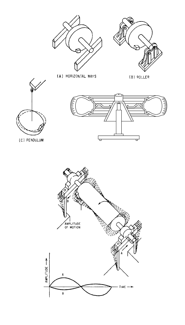
First, consider the simplest type of balancing—usually called “static” balancing,
since the rotor is not spinning. In Fig. 39.9A, a disc-type rotor on a shaft is shown
resting on knife-edges. The mass added to the disc at its rim represents a known
unbalance. In this illustration, in Fig. 39.8, and in the illustrations which follow, the
rotor is assumed to be balanced without this added unbalance weight. In order for
this balancing procedure to work effectively, the knife-edges must be level, parallel,
hard, and straight.
In operation, the heavier side of the disc will seek the lowest level—thus indicat-
ing the angular position of the unbalance.Then, the magnitude of the unbalance usu-
ally is determined by an empirical process, adding mass in the form of wax or putty
to the light side of the disc until it is in balance, i.e., until the disc does not stop at the
same angular position.
In Fig. 39.9B, a set of balanced rollers or wheels is used in place of the knife-
edges.These have the advantage of permitting the rotor to turn without, at the same
time, moving laterally.
In Fig. 39.9C, a setup for another type of static, or “nonrotating,” balancing pro-
cedure is shown. Here the disc to be balanced is supported by a flexible cable, fas-
tened to a point on the disc which coincides with the center of the shaft and is
slightly above the normal plane containing the center-of-gravity. As shown in Fig.
39.9C, the heavy side will tend to seek a lower level than the light side, thereby indi-
cating the angular position of the unbalance. The disc can be balanced by adding
weight to the diametrically opposed side of the disc until it hangs level. In this case,
the center-of-gravity is moved until it is directly under the flexible support cable.
In Fig. 39.9D, a modified version of this setup is shown. The cable is replaced by
a hardened ball-and-socket arrangement (used on many automobile wheel “bubble
balancers”) or by a spherical air bearing (used on some industrial and aerospace bal-
ancers). The inclination of the wheel is then indicated with a centrally mounted
spirit level.
Static balancing is satisfactory for rotors having relatively low service speeds
and axial lengths which are small in comparison with the rotor diameter. A pre-
liminary static unbalance correction may be required on rotors having a combined
unbalance so large that it is impossible in a dynamic, soft-bearing balancing
machine to bring the rotor up to its proper balancing speed without damaging the
machine. If the rotor is first balanced statically by one of the methods just out-
lined, it is usually possible to decrease the combined unbalance to the point where
the rotor may be brought up to balancing speed and the residual unbalance mea-
sured. Such preliminary static correction is not required on hard-bearing balancing
machines.
BALANCING OF ROTATING MACHINERY 39.13
8434_Harris_39_b.qxd 09/20/2001 12:24 PM Page 39.13
39.14 CHAPTER THIRTY-NINE, PART I
FIGURE 39.9 Static (single-plane) balancing devices.
FIGURE 39.10 Motion of unbalanced rotor and
bearings in flexible-bearing, centrifugal balancing
machine.
(A)
(C)
(D)
(B)
8434_Harris_39_b.qxd 09/20/2001 12:24 PM Page 39.14
CENTRIFUGAL BALANCING MACHINES
The following procedures may be used to balance the rotor shown in Fig. 39.8B.
First, select the planes in which the correction weights are to be added; these planes
should be as far apart as possible and the weights should be added as far out from
the shaft as feasible to minimize the size of the weights. Next, by a balancing tech-
nique, determine the size of the required correction weight and its angular position
for each correction plane. To implement these procedures, two types of machines,
soft-bearing and hard-bearing balancing machines, which are described below, are
employed.
Soft-Bearing Balancing Machines. Soft-bearing balancing machines permit the
idealized free rotor motion illustrated in Fig. 39.8B, but on most machines the
motion is restricted to a horizontal plane (as shown in Fig. 39.10). Furthermore, the
bearings (and the directly attached components) vibrate in unison with the rotor,
thus adding to its mass. The restriction of the vertical motion does not affect the
amplitude of vibration in the horizontal plane, but the added mass of the bearings
does. The greater the combined rotor-and-bearing mass, the smaller will be the dis-
placement of the bearings, and the smaller will be the output of the devices which
sense the unbalance.
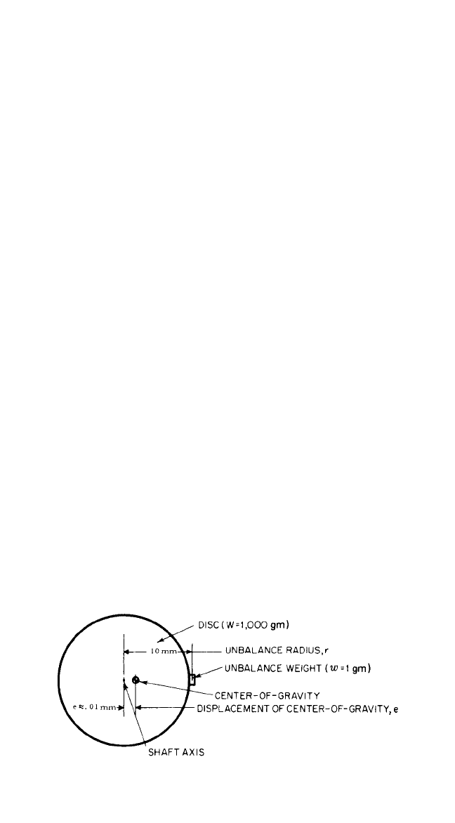
Consider the following example. Assume a balanced disc (see Fig. 39.11) having a
weight W of 1,000 grams, rotating freely in space. An unbalance weight w of 1 gram
is then added to the disc at a radius of 10 mm. The unbalance causes the center-of-
gravity of the disc to be displaced from the shaft axis by
e ==0.00999 mm
Since the addition of the weight of the unbalance to the rotor causes only an insignif-
icant difference, the approximation e ≈ wr/W is generally used. Then e ≈ 0.01 mm.
If the same disc with the same unbalance is rotated on a single-plane balancing
machine having a bearing and bearing housing weight W′ of 1,000 grams, the dis-
placement of the center-of-gravity will be significantly reduced because the bearing
and housing weight is added to the weight W of the disc. The center-of-gravity of the
combined vibrating components will now be displaced by
e′= ≈0.005 mm
The conversion of unbalance into displacement of center-of-gravity as shown in
wr
W + W′
wr
W + w
BALANCING OF ROTATING MACHINERY 39.15
FIGURE 39.11 Displacement of center-of-gravity because of unbalance.
8434_Harris_39_b.qxd 09/20/2001 12:24 PM Page 39.15
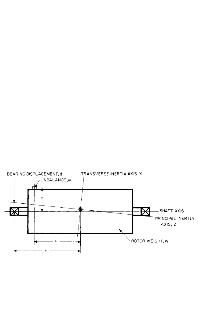
the example above also holds true for rotors of greater axial length which normally
require correction in two planes. However, such rotors are prone to have unbalance
other than static unbalance, causing an inclination of the principal inertia axis from
the shaft axis. In turn, this results in a displacement of the principal inertia axis from
the shaft axis in the bearing planes of the rotor, causing the balancing machine bear-
ings to vibrate.
To find the bearing displacement or bearing vibration amplitude resulting from a
given unbalance is more involved than finding the center-of-gravity displacement,
because other factors come into play, as is illustrated by Fig. 39.12.The weight and
inertia of the balancing machine bearings and directly attached vibratory compo-
nents are usually not known. In any case, they are usually small in relation to the
weight and the inertia of the rotor and can generally be ignored. On this basis, the
following formula may be used to find the approximate bearing displacement d:
d ≈+
where d = displacement at bearing of principal inertia axis from shaft axis
r = distance from shaft axis to unbalance weight
h = distance from center-of-gravity to unbalance plane
s = distance from center-of-gravity to bearing plane
g = gravitational constant
I
x
= moment of inertia around transverse axis X
I
z
= moment of inertia around principal axis Z
wrhs
g(I
x
− I
z
)
wr
W
39.16 CHAPTER THIRTY-NINE, PART I
FIGURE 39.12 Displacement of principal axis of inertia from shaft axis at bearing.
From the above it can be seen that the relationship between bearing motion and
unbalance in a soft-bearing balancing machine is complex. Therefore, a direct
indication of unbalance can be obtained only after calibrating the indicating ele-
ments to a given rotor by use of calibration weights which produce a known
amount of unbalance.
Hard-Bearing Balancing Machines. Hard-bearing balancing machines are
essentially of the same construction as soft-bearing balancing machines except
that their bearing supports are significantly stiffer in the horizontal direction.
8434_Harris_39_b.qxd 09/20/2001 12:24 PM Page 39.16

This results in a horizontal critical speed for the machine which is several orders of
magnitude greater than that for a comparable soft-bearing balancing machine. The
hard-bearing balancing machine is designed to operate at speeds well below its hor-
izontal critical speed. In this speed range, the output from the sensing elements
attached to the balancing-machine bearing supports is directly proportional to the
centrifugal force resulting from unbalance in the rotor.The output is not influenced
by bearing mass, rotor weight, or inertia, so that a permanent relation between
unbalance and sensing element output can be established. Unlike with soft-bearing
balancing machines, the use of calibration weights to calibrate the machine for a
given rotor is not required.
Measurement of Amount and Angle of Unbalance. Both soft- and hard-
bearing balancing machines use various types of sensing elements at the rotor-
bearing supports to convert mechanical vibration into an electrical signal. On
commercially available balancing machines, these sensing elements are usually
velocity-type pickups, although on certain hard-bearing balancing machines, magne-
tostrictive or piezoelectric pickups have also been employed.
Three basic methods are used to obtain a reference signal by which the phase
angle of the amount-of-unbalance indication signal may be correlated with the
rotor. On end-drive machines (where the rotor is driven via a universal joint driver
or similarly flexible coupling shaft), a phase reference generator, directly coupled to
the balancing machine drive spindle, is used. On belt-drive machines (where the
rotor is driven by a belt over the rotor periphery) or on air-drive or self-drive
machines, a small light source projects a narrowly focused beam onto the rotor (usu-
ally the shaft). Its reflection is picked up by a photoelectric cell. Placement of a non-
reflecting mark on the shaft surface will momentarily interrupt the reflection and
thereby furnish the starting point from which the angular position of unbalance in
the rotor is counted. (Stroboscopic lamps, flashing once per rotor revolution, are no
longer considered satisfactory for angle accuracy.) The outputs from the phase-
reference sensor and the pickups at the rotor bearing supports are processed in var-
ious ways by different manufacturers. Generally, the processed signals result in an
indication representing the amount of unbalance and its angular position. In Fig.
39.13 block diagrams are shown for typical balancing instrumentation. In Fig. 39.13A
an indicating system is shown which uses switching between correction planes (i.e.,
single-channel instrumentation). This is generally employed on low-cost balancing
machines. In Fig. 39.13B an indicating system with two-channel instrumentation is
shown. Combined indication of amount of unbalance and its angular position is pro-
vided on a vectormeter having an illuminated target projected on a screen.Two vec-
tormeters give a simultaneous indication for both unbalance correction planes.
Displacement of a target from the central zero point provides a direct visual repre-
sentation of the displacement of the principal inertia axis from the shaft axis. Con-
centric circles on the screen indicate the amount of unbalance, and radial lines
indicate its angular position. Current balancing machines use computerized instru-
mentation with video screens on which the amount and angle of unbalance are indi-
cated in digital format.
Indicated and Actual Angle of Unbalance. An unbalanced rotor is a rotor in
which the principal inertia axis does not coincide with the shaft axis. When rotated
in its bearings, an unbalanced rotor will cause periodic vibration of, and will exert a
periodic force on, the rotor bearings and their supporting structure. If the structure
is rigid, the force is larger than if the structure is flexible. In practice, supporting
structures are neither rigid nor flexible but somewhere in between. The rotor-
BALANCING OF ROTATING MACHINERY 39.17
8434_Harris_39_b.qxd 09/20/2001 12:24 PM Page 39.17
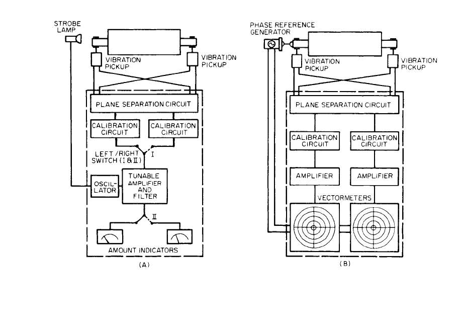
FIGURE 39.13 Block diagrams of typical balancing-machine instrumentations
. (A) Amount of unbalance
indicated on analog meters, angle by strobe light. (B) Combined amount and angle indication on vectormeters.
39.18
8434_Harris_39_b.qxd 09/20/2001 12:24 PM Page 39.18
bearing support offers some restraint, forming a spring-mass system with damping
having a single resonance frequency. When the rotor speed is below this frequency,
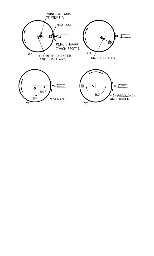
the principal inertia axis of the rotor moves outward radially. This condition is illus-
trated in Fig. 39.14. If a pencil or other marking device is moved toward the rotor
until it touches the rotor, the so-called “high spot” is marked at the same angular
position as the unbalance.When the rotor speed is increased, there is a small time lag
between the instant at which the unbalance passes the pencil and the instant at
which the rotor moves out enough to contact it.This is due to the damping in the sys-
tem. The angle between these two points is called the “angle of lag.” (See Fig.
39.14B.) As the rotor speed is increased further, resonance of the rotor and its sup-
porting structure will occur; at this speed the angle of lag is 90°. As the rotor passes
through resonance, there are large vibration amplitudes, and the angle of lag
changes rapidly. As the speed is increased to approximately twice the resonance
speed, the angle of lag approaches 180°. At speeds greater than approximately twice
the resonance speed, the rotor tends to rotate about its principal inertia axis; the
angle of lag (for all practical purposes) is 180°.
The changes in the relative position of pencil mark and unbalance shown in Fig.
39.14 for a statically unbalanced rotor occur in the same manner on a rotor with
dynamic unbalance. However, the center-of-gravity shown in the illustrations then
represents the position of the principal inertia axis in the plane at which the pencil is
applied to the rotor. Thus, the indicated angle of lag and displacement amplitude
refer only to that particular plane and generally differ from those for any other
plane in the rotor.
Angle of lag is shown as a function of rotational speed in Fig. 39.15: (A) for soft-
bearing balancing machines whose balancing-speed ranges start at approximately
twice the resonance speed; and (B) for hard-bearing balancing machines.The effects
BALANCING OF ROTATING MACHINERY 39.19
FIGURE 39.14 A pencil or marker is held against an unbalanced rotor. (A)
A high spot is marked. (B) The angle of lag. Angle of lag between unbalance
and high spot increases from 0° (A) to 180° (D) as rotor speed increases.
8434_Harris_39_b.qxd 09/20/2001 12:24 PM Page 39.19
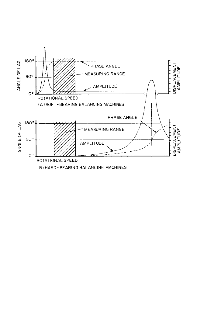
of damping also are illustrated. Here the resonance frequency of the combined
rotor-bearing support system is usually more than three times greater than the max-
imum balancing speed.
Plane Separation. Consider the rotor in Fig. 39.10 and assume that only the
unbalance weight on the left is attached to the rotor.This weight causes not only the
left bearing to vibrate but to a lesser degree the right. This influence is called “cross
effect.” If a second weight is attached in the right plane of the rotor as shown in Fig.
39.10, then the direct effect of the weight in the right plane combines with the cross
effect of the weight in the left plane, resulting in a composite vibration of the right
bearing. If the two unbalance weights are at the same angular position, the cross
effect of one weight has the same angular position as the direct effect in the other
rotor end plane; thus, their direct and cross effects are additive (Fig. 39.16A). If the
two unbalance weights are 180° out of phase, their direct and cross effects are sub-
tractive (Fig. 39.16B). In a hard-bearing balancing machine, the additive or subtrac-
tive effect depends entirely on ratios between the axial positions of the correction
planes and bearings. On a soft-bearing machine, this is not true, because the masses
and inertias of the rotor and its bearings must be taken into account.
If the two unbalance weights on the rotor (Fig. 39.10) have an angular relation-
ship other than 0 or 180°, then the cross effect in the right bearing has a different
phase angle from the direct effect from the right weight. Addition or subtraction of
these effects is vectorial. The net bearing vibration is equal to the resultant of the
two vectors, as shown in Fig. 39.17. The phase angle indicated by the bearing vibra-
tion does not coincide with the angular position of either weight. This is the most
common type of unbalance (dynamic unbalance of random amount and angular
39.20 CHAPTER THIRTY-NINE, PART I
FIGURE 39.15 Phase angle (angle of lag) and displacement amplitude vs. rota-
tional speed in soft-bearing and hard-bearing balancing machines.
8434_Harris_39_b.qxd 09/20/2001 12:24 PM Page 39.20
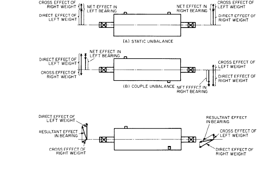
FIGURE 39.16 Influence of cross effects in rotors with static and couple unbalance
.
FIGURE 39.17 Influence of cross effects in rotors with dynamic unbalance. All vectors seen from right side of
rotor.
39.21
8434_Harris_39_b.qxd 09/20/2001 12:24 PM Page 39.21