Harris C.M., Piersol A.G. Harris Shock and vibration handbook
Подождите немного. Документ загружается.

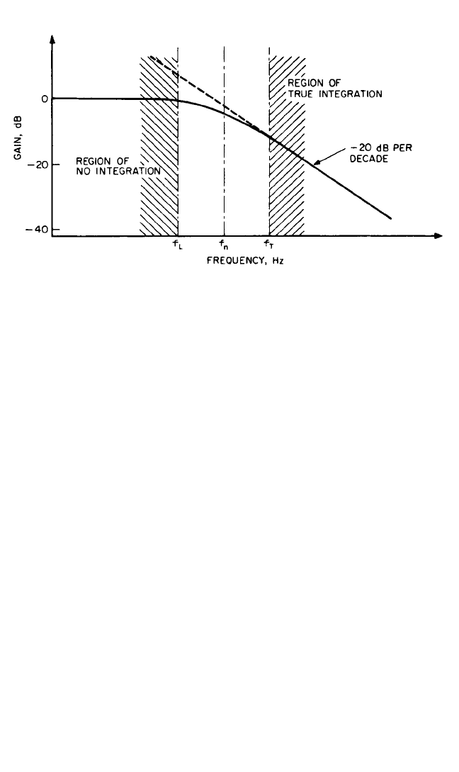
depend to some extent on the actual amplitude and phase characteristics of the inte-
grator, but the following values can be used as a rough guide to select the integrator
cutoff frequency f
T
:
For single integration (acceleration to velocity),
f
T
< (13.5)
For double integration (acceleration to displacement),
f
T
< (13.6)
where t
p
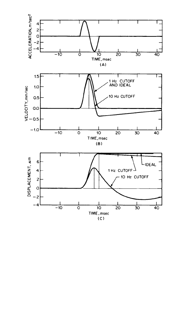
is the time from the start of the pulse to the measured peak. For the case
shown in Fig. 13.5, these values of f
T
are <6.7 Hz and <2 Hz, respectively.
DETECTORS
Detectors are used to extract parameters which characterize a signal, such as arith-
metic average, mean-square, and root-mean-square (rms) values, as defined in Chap.
22. The arithmetic average value is the simplest to measure, using a full-wave recti-
fier to obtain the instantaneous magnitude and a smoothing circuit to obtain the
average. However, even though there is a fixed (though different) relationship
between average and rms values for sinusoidal and Gaussian random signals (Chap.
22), the relationship varies considerably for complex signals and, in particular, is
affected considerably by phase relationships. Since mean-square and rms values are
independent of phase relationships, they are usually preferred as signal descriptors
for stationary signals; where an average detector is used, it is usually as an approxi-
mation of an rms detector.
Mean-square values have the advantage that they are directly additive when two
signals are added together (in particular different frequency bands or components),
1
50t
p
1
30t
p
VIBRATION MEASUREMENT INSTRUMENTATION 13.5
FIGURE 13.4 Frequency characteristic of the circuit shown in Fig. 13.3. f
T
= lower frequency
limit for true integration; f
L
= upper frequency limit for no integration.
8434_Harris_13_b.qxd 09/20/2001 11:14 AM Page 13.5
while rms values have the advantage that they have the same dimensions and units
as the original signal.Thus, a “true rms” detector must include a squaring section and
averager to obtain the mean-square value, followed by a square-root extractor.
Squaring. One of the earliest true rms detectors, the Wahrman detector,
1
used a
piecewise linear approximation to the parabola representing true squaring. For
moderate signal values, the errors for the piecewise linear circuit are quite small, but
past the last breakpoint on the curve the deviation becomes progressively larger.
The breakpoints are dimensioned for a typical rms level, and the errors are thus
13.6 CHAPTER THIRTEEN
FIGURE 13.5 Integration and double integration of a 10-millisecond
acceleration pulse using lower frequency limits of 1 and 10 Hz, respectively.
(A) Input acceleration signal. (B) Velocity signal resulting from a single
integration with different cutoff frequencies compared with ideal integra-
tion. (C) Displacement signal resulting from a double integration compared
with ideal integration.
8434_Harris_13_b.qxd 09/20/2001 11:14 AM Page 13.6

greatest for relatively large instantaneous values, which are characteristic of signals
with a high crest factor (ratio of peak to rms value). The higher the crest factor, the
larger the number of breakpoints required. As an example, four breakpoints give an
accuracy within
1
⁄2 dB for crest factors up to 5. Thus, for accurate results, this type of
detector must be specified with respect to both dynamic range and crest factor.
Later designs of analog squaring circuits, so-called log-mean-square or lms detec-
tors, make use of the logarithmic characteristic of certain diodes to achieve squaring
by doubling the logarithmic value of the rectified signal. This type generally has no
limitation on crest factor other than that given by the dynamic range. In a similar
manner, digital instruments achieve true squaring and are limited only by the
dynamic range of the detector.
Averaging. The definition of mean-square value given in Eq. (22.1) assumes a
uniform weighting for the whole of the averaging time T. In practice, for measure-
ments on continuous signals, it is often desired to have a running average, giving at
any time the average value over the previous T seconds. It is extremely difficult to
achieve a linearly weighted running average, and so recourse is usually made to two
alternatives:
1. Exponentially weighted running average. This is achieved by an R-C smoothing
circuit in most analog instruments, and also by exponential averaging in digital
instruments such as FFT analyzers.
2. Linearly weighted average over a fixed time period of length T. The result is
available only at the end of each period and is usually held until processed fur-
ther, and so new incoming data may be lost.
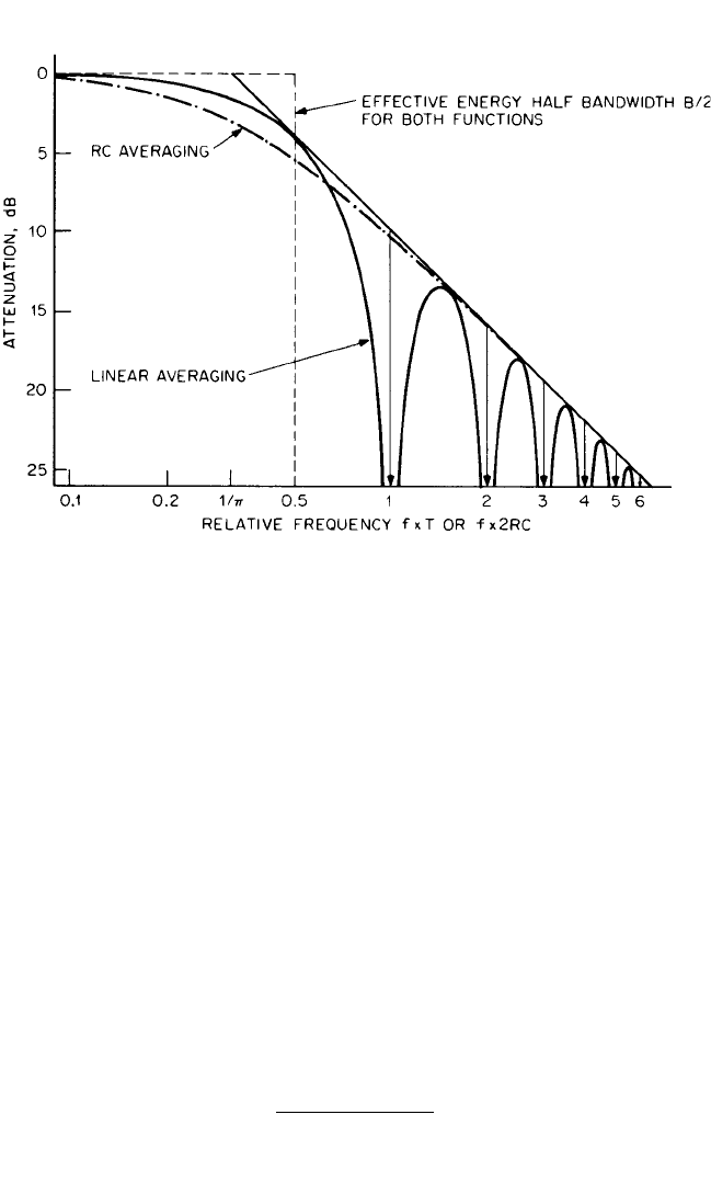
The averaging process acts as a low-pass filter to remove high-frequency ripple
components and leave the slowly varying dc or average value. Figure 13.6 compares
the low-pass filter characteristics of exponential and linear averaging and demon-
strates that they are equivalent for the case where T = 2RC (where RC is the time
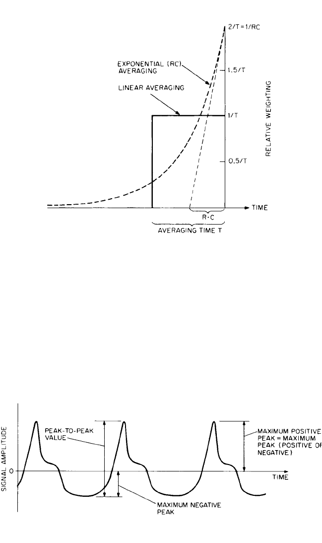
constant of the exponential decay). This low-pass filtration in the frequency domain
corresponds to a convolution in the time domain with the impulse response of the
averaging circuit. The two impulse responses (reversed in time because of the con-
volution) are compared in Fig. 13.7 for the same case where T = 2RC. When scaled
to give the same result on stationary signals (same area under the curve), the peak
output for exponential averaging is twice that for linear averaging.Account must be
taken of this in the analysis of impulses.
A method of checking the effective averaging time of an exponential averager is
to remove the excitation and measure the rate of decay of the output. This will be
4.34 dB per RC time constant, or 8.7 dB per averaging time T. This does not apply to
FFT analyzers operating above their real-time frequency, in the same way that the
effective linear averaging time is then less than the time required to obtain the result.
Peak Detectors. In some cases it is desired to measure the true peak values of the
original signal (for example, to avoid overloading a tape recorder). Peak detectors
are available which capture the highest value encountered and either hold it until
reset or have it decay slowly enough that the eye can read the peak value from a
meter. Care should be taken to distinguish between maximum positive peak, maxi-
mum negative peak, maximum peak (positive or negative), and peak-to-peak values
(Fig. 13.8). Care should also be taken to distinguish between true peak values and
what is roughly referred to as peak-to-peak shaft vibration, which is often assumed
to be sinusoidal and is measured with an average detector.
VIBRATION MEASUREMENT INSTRUMENTATION 13.7
8434_Harris_13_b.qxd 09/20/2001 11:14 AM Page 13.7
Crest Factor. The crest factor is the ratio of peak to rms value.The maximum peak
(positive or negative) should be used. It is meaningful only where peak values are
reasonably uniform and repeatable from one signal sample to another.The crest fac-
tor yields a measure of the spikiness of a signal and is often used to characterize sig-
nals containing repetitive impulses in addition to a lower-level continuous signal.
Examples of such vibration signals are those from reciprocating machines and those
produced by localized faults in gears and rolling element bearings.
Kurtosis. Kurtosis, a statistical parameter akin to the mean and mean-square val-
ues, is defined in Eq. (11.13) as
2
a
4
x
x¯
4
p(x)dx (13.7)
using the terminology of Chap. 11.
For signals with zero mean value
ξ, a practical estimator for this can be ex-
pressed as
T
0
ξ
4
(t) dt
(13.8)
T
0
ξ
2
(t) dt
2
1
T
1
T
13.8 CHAPTER THIRTEEN
FIGURE 13.6 Comparison of linear averaging (over time T) with exponential averaging (time con-
stant RC) in the frequency domain for the case where T = 2RC. The low-pass filter characteristics
have the same asymptotic curves and the same bandwidth B = 1/T = 1/2RC.
8434_Harris_13_b.qxd 09/20/2001 11:14 AM Page 13.8
Because of the fourth power, considerable weight is given to large amplitude values,
and the kurtosis thus is a good indicator of the spikiness of the signal. Because it
takes the whole signal into account, rather than just isolated peaks, it generally gives
a more stable value than the crest factor, but this must be weighed against the more
complicated measurement procedure. Kurtosis is normally calculated digitally, but
can be measured by a more complex version of the log-mean-square detector
described above.
VIBRATION MEASUREMENT INSTRUMENTATION 13.9
FIGURE 13.7 Comparison of linear averaging (over time T) with
exponential averaging (time constant RC) in the time domain for the
case where T = 2RC. The weighting curves represent the impulse-
response functions reversed in time.
FIGURE 13.8 Illustration of various peak values.
8434_Harris_13_b.qxd 09/20/2001 11:14 AM Page 13.9
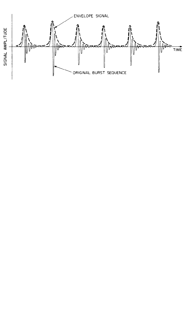
Envelope Detectors. Many machine vibration signals of interest contain repeti-
tive high-frequency bursts, as a result of exciting high-frequency resonances at regu-
lar intervals. Direct frequency analysis of the signal does not always give much
information on the repetition frequencies, in particular when the resonances excited
are at very high frequencies. These repetition frequencies are, however, easily meas-
urable in the envelope signal illustrated in Fig. 13.9. Quite often, the signal is first
bandpass-filtered in a frequency region dominated by the repetitive bursts (i.e., one
of the regions containing resonances which are excited and where the extraneous
background signal is low).
The true envelope signal can be obtained using a peak detector with a decay time
constant set sufficiently short so that it is able to follow the relatively slow variations
in the (rectified) signal envelope. If the signal is first passed through a bandpass fil-
ter, it will have a roughly sinusoidal form with slowly varying amplitude and there
will be a fixed ratio of peak to (short-term) rms or average value, in which case an
rms or average detector can be used instead of the peak detector. Moreover, where
a frequency analysis of the signal is to be obtained with an FFT analyzer, it is not nec-
essary to apply a smoothing circuit, as the antialiasing filters (described below) will
automatically remove high-frequency ripple components in the rectified signal.Thus,
a tunable bandpass filter of, say, one-third-octave bandwidth, followed by a full-wave
rectifier, can be used as an envelope detector in cases where it is primarily the burst
repetition frequencies which are of interest. It is shown in Chap. 14 that envelope sig-
nals can also be calculated by Hilbert transform techniques in an FFT analyzer. In
most cases it is advantageous to analyze the square of the envelope signal,
4
in which
case a squaring circuit can replace the rectifier.
VIBRATION METERS
Vibration meters are instruments which receive a signal from a vibration transducer
and process it so as to give an indication of relevant vibration parameters. They are
sometimes made specifically to meet certain standards, for example, ISO 2372 on
“Vibration Severity of Rotating Machines” or ISO 2631 on “Human Vibration.” In
these cases, the requirements are specified in the relevant standard; the discussion
here is aimed at more general-purpose vibration meters.
For measurements on most rotating machines, a frequency range of 10 Hz to 10
kHz is desirable. The lower limit includes the shaft speed for all machines operating
over 600 rpm and any subharmonic components such as oil whirl for higher-speed
13.10 CHAPTER THIRTEEN
FIGURE 13.9 Illustration of the envelope signal for an impulsive signal containing repetitive
high-frequency bursts.
8434_Harris_13_b.qxd 09/20/2001 11:14 AM Page 13.10

plain bearing machines where such effects are most prevalent. The upper frequency
of 10 kHz includes tooth-meshing frequencies and their harmonics in gearboxes,
bladepassing frequencies in most bladed machines, and resonance frequencies typi-
cally excited by rolling element bearing faults.
It can be advantageous to be able to choose a number of upper and lower limiting
frequencies within the overall range. For example, restriction of the upper frequency
to 1 kHz allows measurements in accordance with ISO 2372 previously cited. For spe-
cial purposes, it may be necessary to go to frequencies lower than 10 Hz, for example,
in measurements on slow-speed machines and on bridges and other structures. It is
possible to cover a total range of 1 Hz to 10 kHz with one accelerometer; if the meter
is able to accept a range of transducers, its own frequency range can be even wider.
If restriction is to be made to one vibration parameter, then velocity usually is the
best choice, as most machine vibration signals have a roughly uniform velocity spec-
trum, so that an increase at any frequency has a roughly equal chance of influencing
overall vibration levels.
It is also desirable to be able to measure acceleration and displacement; changes
at low frequency reflect themselves primarily in the displacement value, while
changes at high frequency have the most effect on the acceleration value.
In addition to the measurement of rms levels in each of the vibration parameters,
it is of advantage to be able to measure some parameter indicating the spikiness of
the signal, such as peak values (and hence crest factor), kurtosis, spike energy, or
shock-pulse value. Finally, it is useful if the meter has an ac output, to allow the sig-
nal to be fed to an oscilloscope, a tape recorder, or headphones. In the absence of
frequency analysis, the human ear can discern a great deal about the characteristics
of a signal, and this setup provides an excellent stethoscope. The ac signal should
preferably be of selected parameter (acceleration, velocity, or displacement); the fre-
quency range should be restricted as little as possible.
TAPE RECORDERS
The most widely used recording techniques for instrumentation tape recorders are
direct recording, frequency-modulation (FM) recording, and digital recording. The
first two are often combined in one recorder and are thus discussed together, while
the latter is discussed separately.
Analog Recorders. In direct recording, the signal amplitude is reflected directly
in the local degree of magnetization of the tape, while in FM recording the ampli-
tude information is contained in the deviation of the frequency of a carrier tone
from its nominal value. Thus, the degree of magnetization of the tape is less critical
for FM recording, and the recorded blips are normally saturated. Hence, one of the
advantages of FM recording is that the recorded signals are less susceptible to
change due to poor storage conditions (heat, light, and stray magnetic fields). On the
other hand, since the carrier frequency is typically 3 to 5 times higher than the max-
imum signal frequency in FM recording, tape speeds (and hence tape quantities
used) must be 3 to 5 times greater for a given frequency range.
The major difference between the two techniques is in their ability to record low-
frequency signals. Since on playback of direct recordings it is the rate of change of
tape magnetization which is detected, this technique cannot record down to dc; a
typical lower frequency limit is 25 Hz. In contrast, FM recording can record down to
dc; a dc signal is simply represented by a constant deviation of the carrier frequency.
Since on playback of direct recordings it is necessary to integrate the detected
signal and compensate for other effects such as tape magnetic properties, this is usu-
VIBRATION MEASUREMENT INSTRUMENTATION 13.11
8434_Harris_13_b.qxd 09/20/2001 11:14 AM Page 13.11

ally done by equalization networks designed primarily to provide amplitude linear-
ity; phase linearity is poor.Thus, the actual form of signals is likely to be modified by
direct recording; peak values cannot be relied upon. The phase linearity of FM
recording is excellent for all except the highest part of the frequency range, where
the effects of the required low-pass filter become significant.
One of the most important characteristics of a tape recorder is its dynamic range,
since the tape recorder is likely to be the element in the measurement chain whose
dynamic range is restricted the most. The dynamic range usually is expressed in
terms of a signal-to-noise ratio, which is typically 40 dB for FM recording and up to
50 dB for direct recording. These figures can be somewhat misleading, however, as
the noise referred to is a total figure over the entire frequency range and has less
influence in a narrow-band analysis. After narrow-band analysis, the noise level for
FM recording typically is more than 60 dB below full scale, as compared with 70 to
90 dB for the digitization noise in a modern frequency analyzer.
Table 13.1 includes a summary of the most important features of FM and direct
recording. Some recorders are able to record using both techniques, in which case the
heads normally are optimized for FM and the signal-to-noise ratio for direct record-
ing is reduced somewhat. The most important addition provided by direct recording
is the possibility of recording considerably higher frequencies, typically 50 to 100 kHz.
Both techniques are limited by the accuracy of the tape transport system, and
small variations in tape orientation and speed give rise to “wow” and “flutter.”
TABLE 13.1 Comparison of Recording Techniques
Direct FM DAT
Dynamic range (typical, narrow-band) 70 dB 60 dB 80 dB
Lower frequency limit (typical) 25 Hz dc dc
Upper frequency limit (typical) 50 kHz 10 kHz 20 kHz
Amplitude stability Acceptable Excellent Excellent
Phase linearity Poor Good Excellent
Preservation of recorded information Acceptable Good Excellent
Digital Recorders. Instrumentation recorders are available based on the pulse-
code modulation (PCM) principle. These have been developed from digital audio-
tape (DAT) recorders and have many characteristics in common. A typical DAT
cassette can record, for 2 hours, two channels to 20,000 Hz, four channels to 10,000
Hz, or more channels with correspondingly lower frequency ranges. Double-speed
versions give twice the number of channels for the same frequency range, but half
the total recording time. For two-channel recording, the overall sampling rate is 96
kHz (48 kHz per channel), each sample being 16 bits, or 2 bytes, so that the overall
amount of data stored on one DAT cassette is well over 1 gigabyte. Newer designs
have a storage capacity of at least 25 gigabytes and allow recording of up to 32 chan-
nels with full 20-kHz frequency range. The problems of wow and flutter are largely
eliminated by digital recorders because the sampling frequency during recording
and playback is not directly tied to tape or rotating-head speed and can be made
extremely accurate. Dynamic range is dependent primarily on the number of bits
used in digitization but typically matches that of digital signal analyzers, giving
approximately 20 dB more than typical analog recorders. Phase matching between
channels is within a fraction of a degree over a very wide frequency range, meaning
that signal reproduction is almost perfect.
13.12 CHAPTER THIRTEEN
8434_Harris_13_b.qxd 09/20/2001 11:14 AM Page 13.12

As with any digital processing, the signal to be recorded must not contain any fre-
quency components above half the sampling frequency. After sampling, it is not pos-
sible to determine whether this condition has been satisfied, and so it is normally
necessary to filter the signals to be recorded with a very steep “antialiasing” filter.
This is typically a 7-pole elliptic filter with cutoff frequency at 40 percent of the sam-
pling frequency and a roll-off of 120 dB per octave. Less steep filters can be used to
reduce the phase distortion effects in the vicinity of the cutoff frequency, but the cut-
off frequency must then be reduced accordingly. To avoid further distortion, it is
common to use digital interpolation techniques to increase the sample rate on play-
back, thus permitting the use of much “gentler” filters to smooth the output from the
digital-to-analog converters.
Table 13.1 compares all three recording techniques.
DIGITAL SIGNAL PROCESSING
Computer software programs are commercially available which provide for signal
processing using digital techniques, for example: FFT analysis, digital filtering, and
optimization. One means of obtaining data in digital form is by using a digital tape
recorder (described in the previous section) in which a digital output is obtained by
bypassing the digital-to-analog converter contained in the recorder. Digital fre-
quency analysis is discussed more fully in Chaps. 14 and 27.This section discusses the
conversion of continuous analog signals which are converted into digital form using
analog-to-digital converters; it also describes some of the differences between ana-
log signal processing and digital signal processing.
ANALOG-TO-DIGITAL CONVERTERS
Analog-to-digital (A/D) converters serve to convert a continuous signal into a
sequence of digital numbers representing the instantaneous value of the signal at
specified time increments. Under certain conditions, it is possible to regain the orig-
inal analog signal by the reverse process, using a digital-to-analog (D/A) converter,
as discussed later. The time increments are normally uniform, i.e., they represent a
constant sampling frequency; in other cases, they may be on some other basis such as
uniform increments of shaft rotation (e.g., in the case of “order tracking,” as dis-
cussed in Chap. 14).
The quality of the digitized signal depends on a number of factors, such as the
accuracy of the sample intervals, the number of bits used in the digital representa-
tion, the linearity of the analog amplifiers with which the signal has been processed,
and the quality of the low-pass filtering of the signal prior to the A/D conversion.
Each of these factors is discussed later.
The first step in the A/D conversion process is the sample-and-hold circuit that
samples the instantaneous value of the analog signal at the instant of each pulse of
the sampling clock, and holds that analog voltage constant until the A/D conversion
process is complete and it is reset. The accuracy of the sample spacing depends not
only on the accuracy of the sample clock, but also on the acquisition time of the
sample-and-hold circuit, but for the frequency range of typical vibration signals,
both of these potential errors are negligible in high-quality A/D converters. For mul-
tiple channel conversion, it is common to use a single A/D converter multiplexing
between channels, but even though it is possible to compensate for time delay
VIBRATION MEASUREMENT INSTRUMENTATION 13.13
8434_Harris_13_b.qxd 09/20/2001 11:14 AM Page 13.13

between channels, it is desirable to use synchronized sample-and-hold circuits which
sample all channels simultaneously, even if the A/D conversion is done sequentially.
The output of an A/D converter is a binary integer number with 2
N
possible val-
ues, where N is the number of bits. Depending on whether a sign bit is used, these can
range from zero to (2
N
− 1) or −2
N − 1
to (2
N − 1
− 1).The possible dynamic range of the
digitized signal is thus heavily dependent on the number of bits used and is com-
monly taken to be 6 dB for each bit (each added bit giving a doubling of the number
of possible levels and a doubling of the ratio of the maximum-to-minimum value).
For averaged spectral results, the dynamic range can be increased somewhat by a
process of adding “dither,” a very low level random noise whose average spectrum is
outside the dynamic range of the measurement system. When dither is added to a
signal lower than the least significant bit (which otherwise would not register) it
causes the latter to be set part of the time and thus gives an averaged result smaller
than the least significant bit (note that the data should be converted from integer to
floating point prior to the averaging process). On the other hand, the actual dynamic
range of the measurement may be limited by factors other than the least significant
bit, such as the noise level in the analog parts of the system, or the linearity of the lat-
ter. For example, it is not uncommon to have a 12-bit A/D converter (which should
give a 72-dB dynamic range) with a linearity specification of 0.05% of full scale, this
corresponding to a possible bias error of −66 dB with respect to full scale. Note that
a bias error of this sort affects all values in the same way, and thus has a much greater
effect than a random error of the same magnitude as is the case when several values
of the same order are added together (e.g., when converting from constant band-
width to constant percentage bandwidth spectra, which is done in some spectrum
analyzers).
ANTIALIASING FILTERS
Discrete sampling in the time domain (i.e., multiplication by a train of unit impulse
functions) corresponds in the frequency domain to a periodic repetition of the spec-
trum with a periodic spacing equal to the sampling frequency, as illustrated in Fig.
13.10. If the original signal does not contain any frequency components above half
the sampling frequency f
s
(i.e., outside the range from minus to plus f
s
/2), this peri-
odic repetition does not result in any loss of information and can in principle be
removed again by low-pass filtering, as shown in Fig. 13.10B. If the sampling fre-
quency is less than twice the highest frequency component in the signal, the periodic
repetition of the spectrum gives mixing of the overlapped portions (known as alias-
ing), and it is no longer possible to separate them completely, as shown in Fig.
13.10C. Thus if it is desired to obtain correct frequency spectra, or to return to ana-
log form via a D/A converter, it is absolutely necessary to ensure that the analog sig-
nal does not contain frequency components above f
s
/2, and this is achieved by the
use of appropriate low-pass filters, so-called antialiasing filters. As explained in
Chap. 14, such filters have very steep characteristics (e.g., 120 dB/octave). Their
application makes it possible to use up to 80 percent of the theoretically available
spectrum (i.e., up to f
s
/2), but they result in considerable phase distortion in the vicin-
ity of the cutoff frequency.
Low-pass filters also change the waveform, as illustrated in Fig. 13.11 for the out-
put of a square-wave generator (giving rise to uneven rectangular pulses so that all
harmonics are produced). In Fig. 13.11A and B, a proper antialiasing filter has been
used, so that the spectrum is correct, but the waveform has bursts at the beginning of
13.14 CHAPTER THIRTEEN
8434_Harris_13_b.qxd 09/20/2001 11:14 AM Page 13.14