Harris C.M., Piersol A.G. Harris Shock and vibration handbook
Подождите немного. Документ загружается.


are examples. Similarly, parametric studies of a particular structure, either to gain an
understanding or to optimize the design, may require a sufficient number of com-
puter runs to justify the development of specialized software. A second type of
special-purpose program includes programs that in some way perform an unusual
type of analysis, for example, the analysis of nonlinear systems. Access to existing
special-purpose programs is generally more restricted than is access to general-
purpose programs, because they are often proprietary and their development
requires a substantial investment.
EXPERIMENTAL APPLICATIONS
The classification experimental applications covers uses of computers which involve,
in some way, the processing of shock and vibration information originally obtained
during the test or field operation of equipment.Two development streams led to the
applications described in later sections, namely, (1) the recognition of the computa-
tional efficiency of the fast Fourier transform (FFT) algorithm (see Chap. 14) and
other advanced digital signal processing algorithms, and (2) the development of
hardware FFT processors, using digital signal processor technology. These develop-
ments permit the use of digital computers for such tasks as vibration data analysis;
shock data analysis; and shock, vibration, and modal testing. The information result-
ing from such applications is in digital form, which permits more sophisticated engi-
neering evaluation of the information through further efficient digital processing,
e.g., regression analysis, averaging, etc.
Digital computers are used extensively in experimental applications such as (1)
the acquisition and processing of shock and vibration data associated with a test or
field operation of equipment, (2) controlling the vibration testing machine used to
accomplish many of these tests, and (3) modal testing. In each of these cases, a digi-
tal computer–based system, along with specialized signal acquisition, signal process-
ing, and signal generation hardware and software, is used to accomplish these
complex applications, as discussed in the following sections.
DIGITAL SHOCK AND VIBRATION DATA ANALYSIS
16
The basic principles of digital shock and vibration data analysis are thoroughly cov-
ered in other chapters and their references, as summarized in Table 27.1. Only meth-
ods that are fundamental to the discussed applications of digital computers that are
not presented elsewhere are discussed here. Specifically, this section discusses (1)
the definition of the estimates of the spectral density and cross–spectral density
matrices used with multiexciter random vibration control systems; (2) tracking fil-
ters for the measurement of the amplitude and phase, as a function of frequency, of
response and control data taken during a swept-sine vibration test; (3) the synthesis
of transient signals that achieve a predetermined shock response spectrum (see
Chap. 26); and (4) frequency response estimation.
Spectral Density Matrix. The spectral density matrix (SDM) is a matrix that con-
sists of both power spectral density values as its diagonal elements and cross–spec-
tral density values as its off-diagonal elements. It is the natural extension to matrices
of the concepts of power spectral density and cross–spectral density that are dis-
cussed in Chap. 22. A SDM is both a Hermitian and a nonnegative definite
matrix.
17–22
It can be estimated as follows.
27.14 CHAPTER TWENTY-SEVEN
8434_Harris_27_b.qxd 09/20/2001 11:51 AM Page 27.14

Let {x(t)} be an N-dimensional column-vector of time-histories, whose compo-
nents are the waveforms x
1
(t),...,x
N
(t).These waveforms could, for example, be the
acceleration responses of a system under test, at N measurement points, that is being
excited by N vibration exciters with the use of N stationary Gaussian drive signals
that are partially correlated (see Chap. 22). If their complex finite Fourier transform
is defined as in Eq. (22.3), with x(t) successively replaced by the x
i
(t) waveforms, the
complex vector {X(f,T)} is obtained, with the finite Fourier transforms, X
1
(f,T),...,
X
N
(f,T), as its components. If the time-history vector {x(t)} has a duration much
longer than T, then as in Chap. 22 it can be partitioned into a series of nonoverlap-
ping segments of data (often called frames), each of duration T, such that the aver-
age can be defined as
[W
XX
(f,T)] =
n
d
i = 1
i
{X
*
1
(f,T) X
*
2
(f,T) ⋅⋅ X
*
N
(f,T)}
i
(27.1)
or using a more compact matrix notation as
[W
XX
(f,T)] =
n
d
i = 1
{X(f,T)}
i
{X(f,T)}
i
H
(27.2)
In Eqs. (27.1) and (27.2), (1) the average is taken as in Table 22.3, where the esti-
mates for the power and cross-spectra are defined using a finite Fourier transform,
(2) X
*
1
(f,T) is the complex conjugate of X
1
(f,T), (3) {X(f,T)}
i
H
is the complex conju-
gate transpose of the vector {X(f,T)}
i
, and (4) the subscript i refers to the ith
nonoverlapping frame. As is shown in Refs. 17 to 19, the above average is an unbi-
ased estimator for the spectral density matrix of the N-dimensional Gaussian sta-
tionary process {X(t)}, which converges to the true spectral density matrix of the
process, {x(t)}, as T and n
d
approach infinity. The use of windowing
17–19
in the defini-
tion of the X
i
(f,T) that are used in Eqs. (27.1), (27.2), and (27.3) reduces the errors
associated with spectral side-lobe leakage (see Chap. 14).
Cross–Spectral Density Matrix. The cross–spectral density matrix (CSDM) is a
matrix that consists of cross–spectral densities between the components of two mul-
tidimensional Gaussian stationary random processes. It is defined similarly as the
previously discussed spectral density matrix. It is the natural extension of the
cross–spectral density concepts that are discussed in Chap. 22. The CSDM is further
discussed in Refs. 17 to 22. For simplicity and without loss of generality, the CSDM
2
n
d
T
X
1
(f,T)
X
2
(f,T)
:
X
N
(f,T)
2
n
d
T
APPLICATION OF DIGITAL COMPUTERS 27.15
TABLE 27.1 Summary of Data Analysis Applications
Application Chapter
Spectral analysis for stationary vibration data 11, 14, 22
Spectral analysis for nonstationary vibration data 22
Correlation analysis for stationary vibration data 11
Probability analysis for stationary vibration data 11, 22
Fourier and shock response spectral analysis of shock data 23
Modal analysis of structural systems from shock and vibration data 21
Multiple input/output analysis of shock and vibration data 21
Average values and tolerance limits for shock and vibration data 20
Other statistical analysis of shock and vibration data 22
Matrix methods of analysis for shock and vibration data 28, Part I
8434_Harris_27_b.qxd 09/20/2001 11:51 AM Page 27.15

estimate is defined in the following discussion for the case where the two random
process vectors have the same dimension.
Let {x(t)} and {y(t)} be two N-dimensional column vectors of time-histories,
which respectively consist of the waveforms x
1
(t),...,x
N
(t) and y
1
(t),...,y
N
(t). The
{x(t)} waveform vector can, for example, be the vector of random drive signals that
are used to excite the system under test, as in Fig. 27.8. The {y(t)} waveform vector in
this case will be the vector of responses, at the N instrumented points located on a
system under test, that is being excited by N-exciters with the use of the drive vector
{x(t)}. If the finite Fourier transform vectors {X(f,T)} and {Y(f,T)} are similarly
defined, with components X
1
(f,T),...,X
N
(f,T) and Y
1
(f,T),...,Y
N
(f,T), it is found
that the average cross-spectrum can be defined as
[W
YX
(f,T)] =
n
d
i = 1
{Y(f,T)}
i
{X(f,T)}
i
H
(27.3)
where the above average is taken as in Eqs. (27.1) and (27.2) but with the use of the
vector {Y(f,T)}
i
instead of the vector {X(f,T)}
i
for the ith nonoverlapping frame. As
in the spectral density matrix estimator in Eqs. (27.1) and (27.2), and as is shown in
Refs. 17 to 19, the above average is an unbiased estimator for the cross-spectral den-
sity matrix between the N-dimensional Gaussian stationary processes {x(t)} and
{y(t)}, which converges to the true CSDM as T and n
d
approach infinity. There are
also convergence results for fixed T when {x(t)} and {y(t)} are ergodic (see Chap. 1)
and with the use of a window function as n
d
approaches infinity for Eqs. (27.1)
through (27.3).
17
Tracking Filters. Tracking filters are specialized filters that implement a narrow
bandpass filter, of selectable bandwidth, centered about the instantaneous fre-
quency of a sine wave with a frequency that is changing with time (commonly called
a sweeping sine wave).
23
These filters are used to extract the amplitude of the sweep-
ing response sine wave, as well as its phase with respect to the modulating signal
used in the tracking filter implementation. This algorithm, based on proprietary
technologies, provides essentially a time-varying estimate of the Fourier spectral
amplitude, in essentially a continuous manner, of a sweeping sine wave,
23
as illus-
trated in Fig. 22.7.
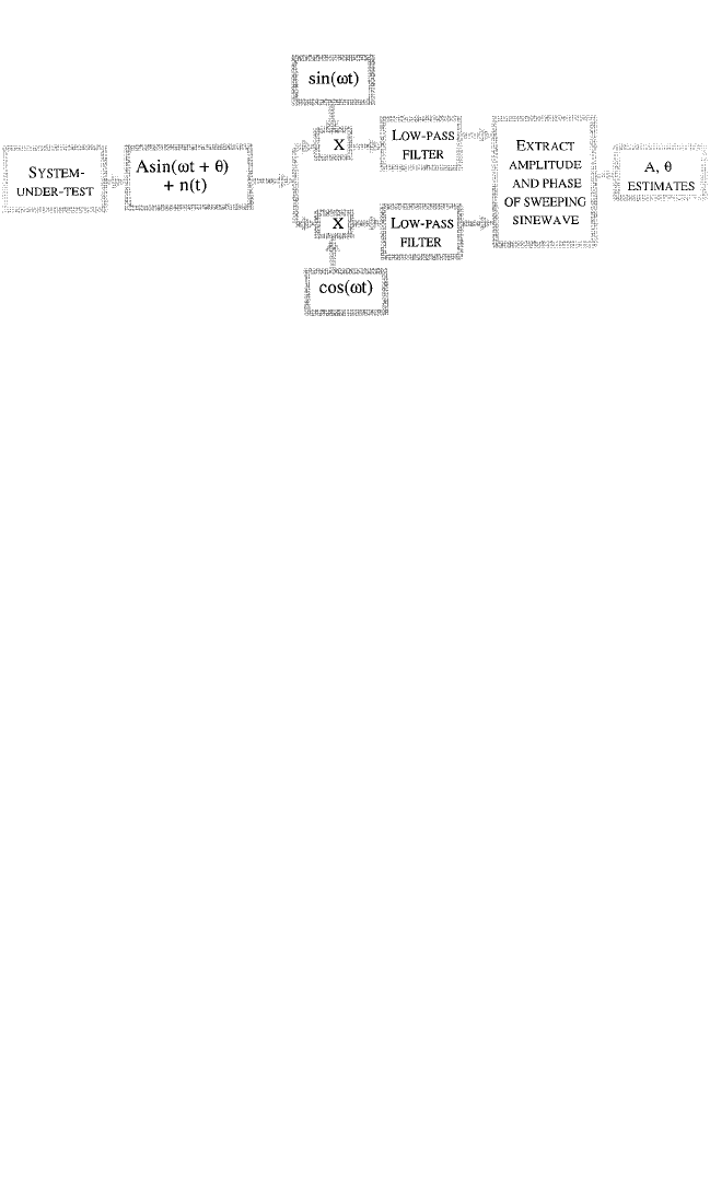
A simplified implementation of a tracking filter is shown in Fig. 27.6. It accepts
a sweeping sine wave response from a system under test that is being excited by a
sweeping sine wave. This response signal is shown as Asin(ωt +θ) + n(t), with a fre-
quency of ω radians/sec, an amplitude A, a phase of θ with respect to the modulat-
ing signals sin(ωt) and cos(ωt), and an additive distortion and noise term n(t). By
modulating the input signal with the sine and cosine terms shown in Fig. 27.6, the
energy at the sweep frequency ω is translated to 0 Hz, hence the name 0-Hz inter-
mediate frequency (IF) detector, where the data detection
23
is accomplished by the
two low-pass filters that produce the imaginary and real-term estimates of the
complex amplitude of the sweeping sine wave response of the system under test.
From these filter outputs, the amplitude A and phase θ, with respect to the modu-
lating signal, are estimated. By analyzing several response signals in this manner
with separate tracking filters that use the same modulating signals, the relative
phase between several sweeping sine wave responses can be measured since their
individual phase measurements have a common phase reference. In this way,
tracking filters can be used for such diverse applications as frequency response
function and matrix estimation, and multiexciter and single-exciter swept sine
wave control.
2
n
d
T
27.16 CHAPTER TWENTY-SEVEN
8434_Harris_27_b.qxd 09/20/2001 11:51 AM Page 27.16
The tracking filter operation shown in Fig. 27.6 provides an estimate of the com-
plex amplitude at the modulating signal’s frequency, which is typically the same as
the swept sine wave’s frequency. It is important that the modulating signals and the
drive signals used to excite the system under test be in frequency and phase syn-
chronization for the best results. Because it can track a sweeping sine wave, it pro-
vides a way of measuring the nonstationary spectral amplitudes associated with
swept sine wave tests and rotating machinery vibration analysis. By its nature, it dis-
cards other terms not centered at the sweep frequency, like unwanted harmonic and
nonharmonic distortion terms. Tracking filters can also be used to track frequencies
other than the fundamental response frequency, like the frequencies of harmonics.
Some modern digital vibration control systems provide the function of Fig. 27.6 by
using dedicated digital signal processors to implement a digital tracking filter sub-
system. These can provide an estimate of a sweeping sine wave’s amplitude and
phase at their sampling rate. Some provide estimates of as many as four to eight
times per cycle of the drive signal.
23
Shock Response Spectrum Transient/Shock Synthesis. Signal synthesis tech-
niques are used in transient testing where the test’s reference response is specified
as a shock response spectrum, as discussed later in this chapter.This type of applica-
tion is often referred to as shock response spectrum synthesis. The primary goal is to
create or synthesize a transient signal with a predetermined shock response spec-
trum. Since the same shock response spectrum is possible for a large range of signals
(see Chaps. 23 and 26), many such synthesis techniques are possible. Some are based
on wavelet expansions
24,25
for pyroshock testing, and others on a transient created by
windowing a stationary random signal (see Chap. 26, Part II).
The methods employed for pyroshock testing are based on the use of a weighted
sum of wavelets, which are defined as a set of orthogonal functions with finite dura-
tions. The wavelets used for shock synthesis are either windowed sine waves with an
odd number of half cycles or damped sinusoids.
24,25
These are used in an inverse
wavelet transform process
24–26
to represent the transients. The transients are chosen
as sums of these wavelets. The amplitude of the wavelets is modified so that the sum
of such wavelets is a transient that achieves the prescribed shock response spec-
trum.
24,25
Since the shock response spectrum definition (see Chap. 23) allows for
many waveforms to have the same shock response spectrum, this many-to-one rela-
tionship allows for the further optimization of the resulting shock-synthesized
transients.
25,27,28
They can be optimized, for example, to produce the least peak accel-
APPLICATION OF DIGITAL COMPUTERS 27.17
FIGURE 27.6 Tracking filter using 0-Hz intermediate frequency (IF) detector.
8434_Harris_27_b.qxd 09/20/2001 11:51 AM Page 27.17

eration for a given peak shock response spectrum. This type of optimization can
increase the peak amplitude of the shock response spectra that are possible with a
particular system under test (see Fig. 27.8), thus extending the performance range of
vibration test machines used for transient/shock testing.
The method used for seismic simulation involves windowed sections of broad-
band Gaussian stationary noise, also known as burst-random transients. These ran-
dom transients are generated using a prescribed magnitude Fourier spectrum,
assigning random phase to it, and using the inverse FFT to create a random transient
with the specified magnitude spectrum. This transient is windowed (see Chap. 14)
and its shock response spectrum is calculated. The calculated shock response spec-
trum is compared with the prescribed shock response spectrum, and the discrepancy
is used to modify the magnitude of its Fourier spectrum. The synthesis iteration is
repeated until the shock response spectrum of the synthesized windowed transient
agrees with the prescribed shock response spectrum within some acceptable error.
Again, the many-to-one characteristic of the shock response spectrum allows for
further optimization of the synthesized random transient.
Frequency Response Function and Frequency Response Matrix Measure-
ments. The computation of frequency response functions and frequency response
matrices make use of the digital signal processor,A/D converter, D/A converter, and
embedded distributed computer systems discussed in a previous section. The objec-
tive of these applications is to excite the system under test in such a way that its
frequency response characteristics can be measured. This type of measurement is
done as part of modal-testing, single-exciter, and multiexciter control systems appli-
cations to be discussed later in this chapter.
Single Input, Multiple Output (SIMO) Methods. In this method, a single drive
signal is used to excite the system under test at any one time. A digital system, like
those shown in Figs. 27.1, 27.2 and 27.5, can be used to drive a system under test and
acquire multiple response signals from instrumentation on the system under test.
The excitation signals can be impulsive, continuous broadband noise, transient noise,
or swept sine waves. In all these cases, the complex-amplitude spectra are measured
for both the drive and response signals by the digital system.The cross–spectral den-
sities between the various response signals and the drive signal, as measured at the
input to the system under test, are divided by the drive signal’s power spectral den-
sity to obtain a frequency response function estimate between the single drive signal
and the response signals (see Table 22.3). Typically broadband noise and swept sine
wave excitations produce the best estimates for the needed frequency response
functions, but at the expense of longer test times that may stress the test article or
system under test. Frequency response functions can be measured, while using swept
sine wave excitation, by using the tracking filters discussed previously.
A multiple-reference frequency response matrix estimate can be obtained by
exciting the system with a hammer or a vibration exciter, one excitation at a time but
at different locations, to successively obtain one column of the frequency response
matrix estimate using this SIMO methodology. These methods may have problems
with repeatability since the structure’s characteristics may change between excita-
tions (see Chap. 21).
Multiple Input, Multiple Output (MIMO) Methods. These methods excite the
system under test with a digital system as in the previous section, but drive it with
multiple simultaneous excitation signals, acquire the associated response signals, and
process the thus-acquired response and drive signals to obtain the needed system
frequency response matrix estimates. Most estimators used are based on the
response equations
17–19
27.18 CHAPTER TWENTY-SEVEN
8434_Harris_27_b.qxd 09/20/2001 11:51 AM Page 27.18

[W
cd
(f)] = [H(f)][W
dd
(f)] or [W
cc
(f)] = [H(f)][W
dc
(f)] (27.4)
where [W
cd
(f)] is an estimate of the cross–spectral density matrix between the
response vector {c(t)} and drive-signal vector {d(t)}, as defined in Eq. (27.3). [W
cc
(f)]
and [W
dd
(f)] are estimates of the spectral density matrices of the response vector
{c(t)} and the drive-signal vector {d(t)}, as defined in Eqs. (27.1) and (27.2), and
[W
dc
(f)] is the complex-conjugate and matrix transpose of [W
cd
(f)].
17–19
The above
two equations that are part of Eq. (27.4) can be solved separately for [H(f)]. The left
equation is relatively insensitive to measurement noise but sensitive to drive-signal
noise, and the right equation exhibits the reverse condition.These types of frequency
response matrix estimates are very similar to the type 1 and type 2 frequency
response estimators discussed in Chap. 21. Here the emphasis is on the use of Eq.
(27.4) with the spectral density matrix and cross–spectral density matrix estimates,
defined in Eqs. (27.1) through (27.3), to estimate [H(f)].The use of Eq. (27.4) for sys-
tem identification will also be discussed as part of the sections on multiexciter digi-
tal vibration control and modal testing.
Note that to use Eq. (27.4), either the matrix [W
dd
(f)] or [W
dc
(f)] needs to be
inverted. For this reason, the left side of Eq. (27.4) is typically used because it is eas-
ier to guarantee that [W
dd
(f)] is not singular rather than [W
dc
(f)]. In many cases,
[W
dc
(f)] is not a square matrix because the dimensions of {c(t)} and {d(t)} are not
equal and clearly [W
dc
(f)] is singular in that case. Some digital systems make an addi-
tional simplification by exciting the system with mutually uncorrelated random
drive signals and thus “ensure” that [W
dd
(f)] is a diagonal matrix. This simplification
can cause additional problems since the measured [W
dd
(f)] will typically not be diag-
onal even if the drive signals are uncorrelated due to unavoidable measurement and
exciter noise. Hence, in practice, it is better to measure [W
dd
(f)] and invert it as a
matrix rather than just inverting its diagonal elements and assuming that its matrix
inverse is diagonal. This is the preferred way to characterize the system under test
for multiexciter control applications to be discussed later. In many of these cases, the
drive signals are measured as inputs to the test article by load cells (see Chap. 12).
The use of MIMO methods can separate modes that correspond to the same
repeated root or eigenvalue (see Chap. 28, Part I), whereas SIMO methods may not
(see Chap. 21).
DIGITAL CONTROL SYSTEMS FOR SHOCK
AND VIBRATION TESTING
The vibratory motions specified for the majority of vibration tests are either sinu-
soidal
23,29
or random
29
(see Chap. 20).A smaller percentage of the vibration tests are
prescribed to be either a classical-shock transient
27
(see Chap. 26, Part I), a shock
response spectrum synthesized transient (see Chap. 26, Part II), a long-term
response waveform,
30
or mixed-mode
31
(sine-on-random or narrow bandwidth
random-on-random) vibratory motions. These specified environments are typically
represented by a reference response signal, in either the time or frequency domain,
that the digital control system servo uses as a control reference to achieve the spec-
ified control response at the chosen control point or points that are associated with
the test (see Chap. 20).
The reference response is either a frequency-domain or time-domain signal that
represents the specified vibration environment associated with a shock or vibration
test. It is typically specified as a reference spectrum, which describes the vibration
APPLICATION OF DIGITAL COMPUTERS 27.19
8434_Harris_27_b.qxd 09/20/2001 11:51 AM Page 27.19
environment in the frequency domain to which the control response spectrum is
compared as part of the digital vibration control process. It could be a power spec-
tral density for a random vibration test, an amplitude vs. frequency profile for a
swept-sine test, a shock response spectrum for a shock test, or a finite Fourier spec-
trum (see Chaps. 20 and 22) for a generalized transient or a long-term reference
response waveform test. Time-domain vibration environments, like transient and
long-term response waveforms, are represented by a reference pulse or reference
waveform, whereas frequency-domain-specified environments like random, swept-
sine, and shock response spectrum synthesis shock tests, are specified with an appro-
priate reference spectrum. Typically, the time-domain reference signals are
converted to the frequency domain as part of the feedback control and drive-signal
synthesis process, using an appropriate time-to-frequency and frequency-to-time
transformation process.
Vibration tests are accomplished with the use of vibration test machines, as dis-
cussed in Chap. 25, and a digital vibration control system (DVCS). The DVCS
employed to control the vibration level(s) during the test typically utilizes the out-
put signal from a control transducer (usually an accelerometer) mounted at an
appropriate location on the vibration exciter’s test fixture (part of the vibration test
machine) or the unit under test (UUT) to provide a feedback signal to its servo sys-
tem. The servo system in turn drives the power supply of the vibration testing
machine used for the shock or vibration test. The servo system is largely imple-
mented digitally using analog-to-digital (A/D) converters, digital-to-analog (D/A)
converters, digital signal processors (DSPs), embedded processors, and general-
purpose processors, to adjust the drive-signal amplitude and spectrum for the system
under test so as to maintain the control transducer’s response level and waveform
characteristics as close to the test’s specified reference response as possible.
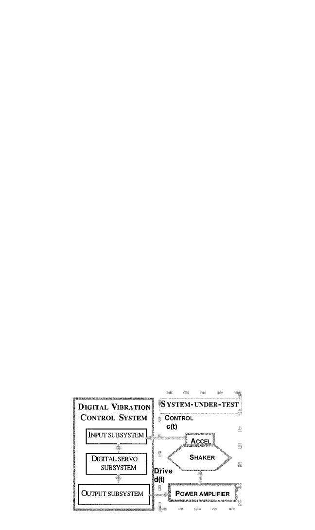
The overall block diagram of the vibration test system, when using electrody-
namics exciters and accelerometers for control transducers, is shown in Fig. 27.7. In
this case, the DVCS drives the system under test with an analog drive signal, d(t),
such that the control response at the chosen control-point location on the system
under test agrees with the specified reference response with an acceptable error.The
DVCS consists of (1) an input subsystem, which acquires the response waveform of
the system under test, c(t); (2) the digital servo subsystem, which creates the digital
drive signal through a closed-loop process that causes c(t) to agree with a suitable
description of the specified test reference signal; and (3) the output subsystem,
27.20 CHAPTER TWENTY-SEVEN
FIGURE 27.7 General setup for vibration test system.
8434_Harris_27_b.qxd 09/20/2001 11:51 AM Page 27.20
which converts the digital description of the generated drive signal into an equiva-
lent analog drive signal, d(t), used to drive the system under test.
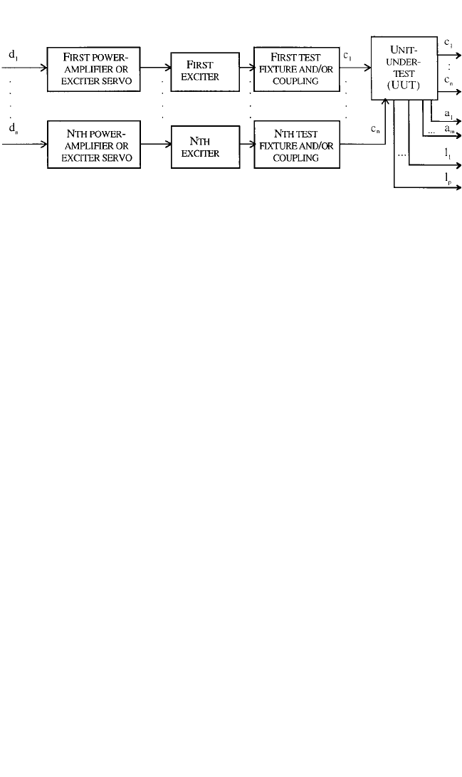
A typical system-under-test configuration for both single and multiple exciters is
shown in Fig. 27.8. If there is only one exciter involved, then only the top leg of the
block diagram in Fig. 27.8 is used. Here, d
i
means the drive signal generated by the
DVCS that is used to drive the ith exciter. This drive signal is sent to the exciter’s
power amplifier (when using electrodynamic exciters), which in turn drives the
exciter. For electrohydraulic exciters, this drive signal is sent to the exciter’s servo
amplifier, which in turn drives the hydraulic servo-valve subsystem, as discussed in
Chap. 25. The exciter, either electrohydraulic or electrodynamic, then drives a test
fixture (see Chap. 20), which in turn drives the unit under test. The test is either
instrumented by mounting control transducers, which are typically accelerometers
(see Chap. 12), on the test fixture, here shown by the signal c
1
through c
n
, or on the
UUT as shown by the signals c
1
through c
n
in Fig. 27.8. These chosen control signals
are then sent to the input subsystem of the DVCS where they are either averaged or
their maximum or minimum, as a function of frequency, is extracted to create a com-
posite response spectrum.
The signals a
1
through a
m
in Fig. 27.8 are additional or auxiliary responses of the
UUT that are monitored during the test as additional signal channels to be analyzed
as part of the test. The signals l
1
through l
p
are input channels that are to be used for
limiting during the test. This limiting may involve either limits on the response or
limits on the applied force to the UUT, as discussed in Chap. 20. For multiexciter
applications, there are n exciter systems with n drive signals, d
1
through d
n
. These
drive signals are processed as in the single exciter case discussed before. The basic
difference is that the n exciters will drive the UUT jointly through the fixture that
connects the UUT to the multiple exciters. The response to this vector of drive sig-
nals is also a vector comprised of the control responses c
1
through c
n
. This test con-
figuration and its associated control methods are further discussed in a subsequent
section. In either the single- or multiexciter control configuration, the control feed-
back signals, auxiliary response signals, and the limit signals are routed to the input
subsystem of the DVCS.
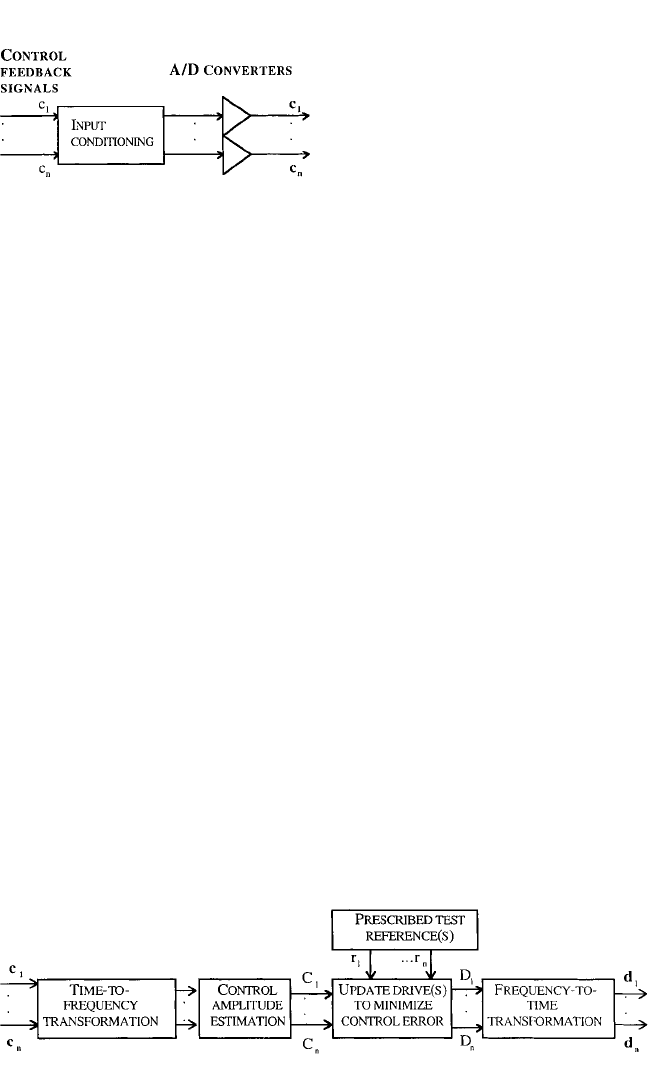
A block diagram of the input subsystem is shown in Fig. 27.9. Here only the
control-feedback signals are shown as inputs to the DVCS’s input subsystem. These
feedback signals, also called control-response channels, or simply control signals, are
each sensed through an input signal conditioning system and analog-to-digital
(A/D) converter subsystem. The input signal conditioning typically consists of an
instrumentation amplifier, followed by a ranging amplifier to optimize the signal’s
amplitude as presented to the A/D converter, and an antialiasing filter (see the input
APPLICATION OF DIGITAL COMPUTERS 27.21
FIGURE 27.8 General setup for multiple-exciter vibration test system.
8434_Harris_27_b.qxd 09/20/2001 11:51 AM Page 27.21
subsystem in Fig. 27.2). This condi-
tioned analog signal representing the
chosen response signal is finally pre-
sented to the A/D converter subsystem
for conversion into a digital time-
history.
Typically, other points on the UUT
or on the vibration test machine are
also monitored by the digital control
system for subsequent vibration analy-
sis or limiting. The input subsystem
then sends digitized versions of the
control signals, here represented by the c
1
through c
n
, to the DVCS’s servo subsys-
tem, as shown in Fig. 27.10.The digital control-response time-series, c
1
through c
n
, are
then sent to a time-to-frequency block shown in Fig. 27.10.The function of this block
varies with the type of vibration control. For random vibration testing, this block
estimates the control-response power spectral density. For swept-sine vibration test-
ing, this block typically produces either the fundamental amplitude or the overall
response root-mean-square (rms) estimate using tracking filters or variable time-
constant rms detectors.
29
For other types of vibration testing, this block is typically
an FFT estimator (see Chap. 23). These estimates are further processed to produce
either a single control-response spectrum, C
1
, for single shaker control, or a control-
response vector, with components C
1
through C
n
, for multishaker control. The type
of processing is again application-specific. These control-response amplitude esti-
mates are then sent to a block that updates the drive-signal amplitude and spectrum
to minimize the difference between these control-response amplitudes and the spec-
ified test reference for single-shaker control, or the test’s reference-response vector
for multishaker control applications. The updated drive amplitude(s) and their
respective spectra are then sent to a frequency-to-time transformation block, which
converts the spectral representation of the drive signal(s) into a digital time series of
the time-domain drive that will be used to excite the system under test as previously
described. This digital time-series signal or vector, comprised of d
1
through d
n
for
multishaker control, is then sent to the output subsystem (see Figs. 27.5 and 27.11)
for conversion into an analog signal or signals to be used to drive the previously dis-
cussed system under test in Fig. 27.8. The output subsystem is shown in Fig. 27.11.
The digital version of the drive signal or signals are synthesized to analog-driving
voltages by the system’s output subsystem. These digital drive signals are then con-
verted into analog signals by the subsystem’s D/A converters. The D/A converter
output signals are filtered to eliminate the images generated by the D/A converters,
and the final output is attenuated from the D/A converter’s full-scale voltage to pro-
duce the proper amplitude exciter drive signal d
1
for single-shaker control or drive-
27.22 CHAPTER TWENTY-SEVEN
FIGURE 27.9 Input subsystem for digital
vibration control system.
FIGURE 27.10 Servo subsystem for digital vibration control system.
8434_Harris_27_b.qxd 09/20/2001 11:51 AM Page 27.22
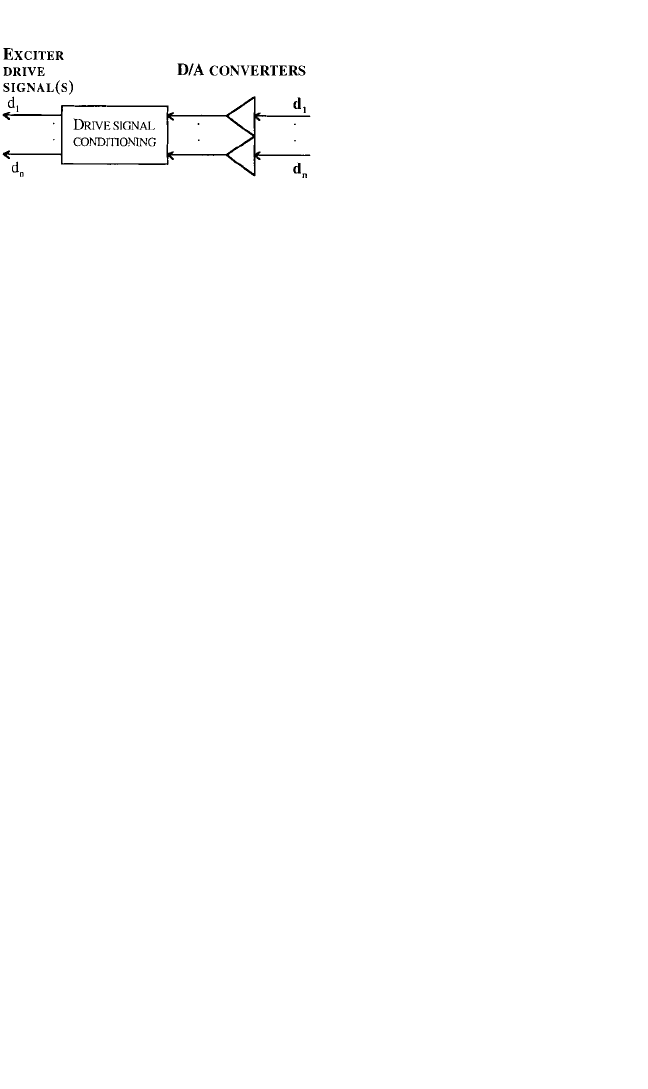
signal vector for multiexciter control
(see Fig. 27.5). These conditioned ana-
log drive signals are output by the
DVCS to drive the system under test.
Initially, with the advent of dedi-
cated FFT processors and minicomput-
ers, it became possible to perform
spectral analysis of random processes
rapidly enough to permit the use of
digital control systems for random
vibration testing. Further develop-
ments in digital signal processors,
embedded and distributed processors, personal computers, and workstation tech-
nologies extended the range of vibration testing to include swept-sine, transient
waveform, long-term waveform, and multishaker testing. Most shock and vibration
testing remains based on single-shaker methods, but multishaker testing is becoming
more important when the size and weight of the UUT dictates its need, or when the
prescribed vibratory motions are inherently multiaxis or otherwise consist of multi-
ple degree-of-freedom vibratory motions.
30,32,33
Enough differences exist between
single- and multishaker digital control systems for these to be discussed separately
in the following sections. The previous discussion, however, illustrates the areas
where they are similar.
Single-Exciter Testing Applications. The great majority of shock and vibration
testing is specified and accomplished with the use of single exciters or shakers.These
are typically single-axis tests. Multiaxis test specifications are accomplished one axis
at a time when using single exciters. Random, swept-sine, mixed-mode, transient
waveform, and long-term response waveform vibration applications can be accom-
plished as long as the vibration test machine capabilities and the weight and size of
the unit under test allow it (see Chap. 25).
In many single-exciter vibration tests, especially random and swept-sine tests, even
though only a single drive signal is employed, multiple control accelerometer input
channels are used. In these cases, the multiple control signals are combined by aver-
aging them or by selecting the largest or smallest response, as a function of frequency,
to create a composite control-response spectrum, with the control-estimation block
in Fig. 27.10. Often multiple input channels are additionally used for limit control, as
discussed earlier.The single-shaker control applications that use a single drive signal
to excite the system under test, and use multiple input control signals and/or limit sig-
nals, are called multiple input, single output (MISO) control systems.
Random. These systems excite a test item with an approximation of a station-
ary Gaussian random vibration (see Chap. 2). Digital random vibration control sys-
tems use signal processing that mimics analog methods in their fundamental control
and measurement methods [see Eq. (22.7)] and offer significant user-interface and
graphics subsystems that provide greater system tailoring and varied displays and
graphs of ongoing test conditions. Digital systems also afford greater stability, more
freedom in the control methods, and superior accuracy than those control systems
that directly use analog methods.
29
The control-response waveforms from the system under test are low-pass filtered
to prevent aliasing (see Chaps. 13 and 22) and converted to a sequence of control
samples by the input subsystem of the digital system as previously discussed. The
averaging control, the spectrum analyzer, and the display are implemented by the
time-to-frequency and control-amplitude estimation blocks. These blocks use a dis-
APPLICATION OF DIGITAL COMPUTERS 27.23
FIGURE 27.11 Output subsystem for digital
vibration control system.
8434_Harris_27_b.qxd 09/20/2001 11:51 AM Page 27.23