Harris C.M., Piersol A.G. Harris Shock and vibration handbook
Подождите немного. Документ загружается.


crete Fourier transform (DFT), as discussed in Chap. 14, to estimate the power-
spectral density (see Table 22.3) of the control responses c
1
(t) through c
n
(t). The ran-
dom noise generator and the analog equalizer, used in previous analog random
vibration systems, are replaced by an analogous digital process using a DFT and a
time-domain randomization algorithm.
29
This is accomplished in the frequency-to-
time processing block within the DVCS in Fig. 27.10.The lines of the DFT (see Chap.
14) in the digital system play the role of the contiguous narrowband filters in the
equalizer of the analog system.
29
Equalization is the adjustment of the amplitude of
the output of a bank of narrowband DFT filters, which is an FFT equivalent (see
Chap. 22), whose amplitude is given by the drive signal’s spectrum amplitude, D
1
(f),
that correspond to the center frequency of each DFT filter, such that the power spec-
tral density of the control response matches that of the test-prescribed reference.
The equalization of the drive waveform can be accomplished directly, by gener-
ating an error correction from the difference between the control power-spectral
density and the reference spectral density. The equalization can also be accom-
plished indirectly through a knowledge of the system frequency response function
magnitude. The required system frequency response function (see Chap. 21) is the
ratio of the Fourier transform of the control response (usually an acceleration) and
the Fourier transform of the drive-voltage signal, as is discussed in an earlier section.
Only the magnitude of the frequency response function is required for random con-
trol, since the relative phase between frequencies is random and not controlled.
The drive spectrum D
1
, that results from the “update drive to minimize error”
block in Fig. 27.10, is multiplied by a random phase sequence and its inverse FFT is
calculated to create the corrected drive time series d
1
(t). Samples of the corrected
digital drive time series, d
1
(t), are fed through the output subsystem in Fig. 27.11
within the DVCS, converted to an analog signal, low-pass filtered to remove the
images caused by the D/A converter, further amplified, and then sent as the analog
signal d
1
to the power amplifier input of the system under test, which completes the
loop. Corrections to the drive are not made continuously in the digital random-
vibration control system. Many samples of the drive (often thousands) are output
between corrections. Many digital systems use a time-domain randomization
process
29
that converts the finite duration d
1
(t) drive block into an indefinite dura-
tion signal with a continuous power spectral density that has the same values as
d
1
(t)’s at the discrete frequencies at which the FFT was evaluated.The time between
drive corrections is called the loop time. The loop time for digital random vibration
control systems can be from a fraction of a second to a few seconds depending on the
type of averaging used for control-response power spectral density estimation.
The speed at which the system can correct the control spectrum is determined by
two factors. The first is the loop time, and the second is the number of spectral aver-
ages required to generate a statistically sound estimate of the control power spectral
density (see Chap. 22). The loop time is usually the shorter of the two. Typically, a
compromise is required; an estimate of the power spectral density with a significant
error is used, but only a fraction of the correction is made in each loop. The type of
spectrum average, linear or exponential, also has a large effect on the averaging time
where the exponential average affords a shorter averaging period, but only a frac-
tion of a correction is made in each control loop to ensure system closed-loop sta-
bility.
29
In such cases, multiple corrections occur within the averaging period. The
equivalent bandwidth of the DFT filters is dependent on the number of lines in the
DFT, the type of spectral window that is used (see Chap. 14), and the sampling rate
of the D/A and A/D converters. These parameters are usually options chosen by the
operator either directly or indirectly. The averaging parameters are also typically
operator-specified.
27.24 CHAPTER TWENTY-SEVEN
8434_Harris_27_b.qxd 09/20/2001 11:51 AM Page 27.24

Swept-Sine. The objective of a digital sine wave vibration test control system is
to drive a system under test, as shown in Fig. 27.8, with a sweeping sine wave excita-
tion such that the control-response signals, when processed by the control-response
estimation block shown in Fig. 27.10, agree with the specified test reference within
some acceptable error. The control-response outputs, c
1
through c
n
, of the system
under test are filtered and digitized with the input subsystem of the DVCS. The
needed tracking filters,
23
variable time-constant rms detectors,
29
averaging control,
and control signal selection are implemented within the appropriate blocks in Fig.
27.10 by the use of an embedded DSP subsystem for the required specialized signal-
processing functions. It is however nontrivial to implement tracking filters digitally,
23
as previously discussed. Many systems, in the interest of simplicity, do not use true
tracking filters, but approximate this function by using FFT methods. In any case,
these are implemented in the time-to-frequency transformation and control-
amplitude estimation blocks within the servo subsystem in Fig. 27.10 within the
DVCS.
The sine-wave generator is implemented by using samples of a digitally gener-
ated sine wave, usually by a digital signal processor subsystem within the frequency-
to-time transformation block in Fig. 27.10, which are sent to the output subsystem in
Figs. 27.5 and 27.11, to be used to drive the system under test in Fig. 27.8. The swept-
sine test parameters are entered by the test operator through the DVCS’s graphical
user interface to be stored in a test parameter file for use in a subsequent test. The
control-response servo subsystem shown in Fig. 27.10 is implemented by an algo-
rithm that compares the computed amplitude of the control waveform with the
required control amplitude, as defined by the test setup, and generates a corrected
sampled drive waveform.This function is accomplished by the “update drive to min-
imize control error” block shown in the DVCS’s servo subsystem block diagram in
Fig. 27.10. The sampled drive waveform is converted to an analog drive waveform by
the D/A converter and sent to the low-pass filter and output attenuator shown in
Fig. 27.5, which illustrates the DVCS’s output subsystem block diagram shown in Fig.
27.11. This resultant analog drive signal, d
1
, is used as the input to the power ampli-
fier within the system-under-test block diagram in Fig. 27.8 to complete the closed
loop.
Swept-sine vibration tests can require that the frequency be stepped in a
sequence of fixed frequencies, or swept in time over a range of frequencies. How-
ever, the stepped approach can generate vibration transients every time the fre-
quency of the sine-wave drive signal is changed. A swept sine is the changing of the
frequency from one frequency to another in a smooth continuous manner.This is the
preferred drive-signal generation method since it creates no significant transients as
the frequency is changed.Again, many commercial control systems use the stepped-
frequency method because of its simpler implementation.The rate of change of fre-
quency with respect to time is called sweep rate. Both logarithmic and linear swept
sines are required. For a logarithmic sweep, the change in the logarithm of the fre-
quency per unit of time is a constant. For a linear sweep, the change in frequency per
unit of time is a constant. Because the drive waveform is usually generated in blocks
of samples, care must be taken in swept-sine vibration tests to ensure that the fre-
quency and amplitude change is continuous.The correction of the drive amplitude in
a digital system is not continuous, but discrete. The time between amplitude correc-
tions is also called the loop time, and is controlled by the number of samples that
must be taken to define the control-waveform amplitude and the required compu-
tations to compute the corrected drive waveform. Here as in the other DVCS appli-
cations, a control loop iteration is the completion of one complete cycle from the
correction of one drive waveform to the next.
APPLICATION OF DIGITAL COMPUTERS 27.25
8434_Harris_27_b.qxd 09/20/2001 11:51 AM Page 27.25

The control-response amplitude can vary rapidly as the frequency changes due to
system resonance, and the required loop time is measured in small fractions of a sec-
ond. For stability, the complete correction of the drive waveform is not usually made
in each loop. The maximum rate of drive waveform correction is called the compres-
sion speed
29
and is usually expressed as decibels per second (dB/sec). If the com-
pression speed is too fast, system instabilities can occur. If the compression speed is
too slow, the correct amplitude will not be maintained. The required compression
speed is a function of (1) frequency, (2) sweep rate, (3) the system dynamics, (4) the
amount of noise present in the response measurement, and (5) the degree to which
the response of the system under test is nonlinear. Limited operator control of the
compression speed is usually provided. The bandwidth of the digital tracking fil-
ter
23,29
will affect the stability of the system. Specifically, as the bandwidth of the
tracking filter decreases, the delay in the output of the tracking filter increases.
23
As
the filter delay increases, the compression speed must be decreased to maintain sta-
bility.
29
Some of the more advanced DVCSs used for this purpose accommodate the
change in correction rate automatically to ensure a good compromise between con-
trol speed and accuracy. However, the user needs to make the required compromise
by selecting the bandwidth of the tracking filter or the time constant of the rms
measurement to be used during the swept-sine test, which trades off the ability to
reject components in the control waveform at frequencies other than the drive fre-
quency, and the ability of the control system to respond quickly to changes in the
control waveform amplitude.
Transient/Shock. Sometimes it is desirable to perform shock or transient test-
ing using electrodynamic or electrohydraulic vibration test machines.
24
The ability to
employ this method is dependent on such parameters as the stroke (the maximum
allowable motion of the vibration exciter); the peak amplitude, spectral characteris-
tics of the specified transient waveform; the amount of moving mass during the test;
and the test time. If the required test is within the performance capability of an avail-
able vibration test machine, the ability to obtain and control the desired motion has
been greatly expanded by the use of digital control equipment.
24,27
In general, the
servo control of a shock test parallels that used for the other vibration-control meth-
ods but, in this case, the controller compares the control accelerometer time-history
response to a reference waveform as part of the control process. The primary differ-
ence here is that the time-to-frequency and frequency-to-time transformations in
Fig. 27.10 are accomplished using an FFT of the transient with the forward or inverse
transformations, respectively. If necessary, the controller drive signal is altered to
minimize the deviation of the control accelerometer response from the reference
based on the comparison between the control-response and reference-response FFT
spectrum.This discrepancy is used to update the drive spectrum in the “update drive
to minimize control error” processing block within the DVCS’s servo subsystem in
Fig. 27.10.
Shock-test requirements may be specified in one of two ways. The first and more
direct method specifies a certain acceleration waveform, such as a half-sine pulse of
specified duration and maximum acceleration. These are called classical-shock tran-
sients (see Chap. 26, Part I). The DVCS in this case needs to modify such classical
pulses by adding a pre- and postpulse to the overall test pulse waveform
27
to ensure
that the response of the system under test returns to a zero acceleration, velocity,
and displacement conditions at the end of the shock test. Typical pulses used as the
reference-response waveform, r(t), in addition to the previously discussed half-sine
pulse, include final and initial-peak sawtooth, rectangular, and trapezoidal pulses of
varying duration and amplitudes (see Chap. 26, Part I). The control method that is
used is a subset of what is used for long-term response-waveform control, discussed
27.26 CHAPTER TWENTY-SEVEN
8434_Harris_27_b.qxd 09/20/2001 11:51 AM Page 27.26

in a later section, usually without a need for the overlap and add indirect convolu-
tion method.
1
The second method employs the shock response spectrum (see Chaps. 23 and 26,
Part II) as the means of characterizing the response of the control points.
25,28
In this
case, the control-response spectrum, C(f), and the reference-response spectrum,
R(f), are specified as a shock response spectrum.The requirements for the reference
shock response spectrum must specify the frequency range, frequency spacing,
damping factor, type of spectrum, and either maximum or nominal values with an
allowable tolerance on spectrum values.
24,28
Reference pulses are generated using
one of the shock response spectrum synthesis techniques
24,25
discussed previously.
The control method that is used is called the wavelet amplitude equalization (WAE)
method. If the test requirements are specified as a shock response spectrum refer-
ence, R(f), then during the test the shock response spectrum of the control-response
waveform is computed and compared with the prescribed R(f). The difference is
then used to update the drive signal, which is expressed as a weighted sum of
wavelets. The weights in the sum represent the amplitude of the various wavelets.
These amplitudes are varied as a function of the discrepancy of the control-response
shock response spectrum and the reference shock response spectrum. Care is
required when this difference is large since the control problem is highly nonlinear
due to the nonlinear dependence of the control-response shock response spectrum
to the wavelet amplitudes of the drive signal. Because of this, the control corrections
are iterative and yield an approximate shock response spectrum for the control
response.
Mixed-Mode. Digital vibration test control systems are available which can
control several sine waves superimposed on a stationary random vibration test.
31
This is called sine-on-random vibration testing or swept-sine-on-random vibration
testing. Systems are also available that can control swept narrow bandwidths of non-
stationary random superimposed on a stationary random vibration test. This is
called swept-narrow-bandwidth-random-on-random testing. It uses a variation of the
random vibration control methods, previously discussed, by modifying the reference-
response spectrum during the test to create sweeping narrow bandwidths of random
that are superimposed on a broad-bandwidth random background.
31
The control or
servo-process for the case of sine-on-random works as a parallel connection of a
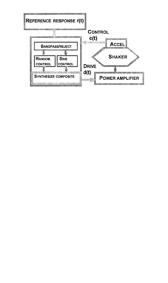
random vibration and a swept-sine control system. A simplified block diagram of
this process is shown in Fig. 27.12.
The two critical differences between mixed-mode controllers and individual ran-
dom and swept-sine controllers are the presence of the bandpass/reject and synthe-
size composite subblocks in Fig. 27.12. The bandpass/reject subblock in Fig. 27.12
separates the swept-sine and random backgrounds into two separate signal streams.
The swept-sine component is fed into the sine control section and the random back-
ground section is fed into the random control section. These separate controllers,
with needed synchronization between each other, then create separate drive-
amplitude updates for control of their respective component. These separate drive-
amplitude updates are combined into a composite drive signal, containing the
random and swept-sine components in a single drive signal, by the synthesize com-
posite section in Fig. 27.12.This composite drive is then sent to the system under test
to complete the control loop. The bandpass/reject section should employ advanced
signal-estimation techniques to determine the phase and amplitude of the control-
response sinusoids that are masked by the background random noise contained in
the composite control-response signal, c(t).
Long-Term Response Waveform Control. The objective of a long-term
response waveform control, or simply waveform control, test is to drive the system
APPLICATION OF DIGITAL COMPUTERS 27.27
8434_Harris_27_b.qxd 09/20/2001 11:51 AM Page 27.27
under test in Fig. 27.8 with a drive signal, d(t), such that the time-domain response of
the chosen control transducer [c
1
(t) in Fig. 27.8] matches the test-specified reference
waveform r(t) within an operator-specified error margin. The same type of DVCS
shown in Figs. 27.7 through 27.11 can be used for this application. The DVCS is
tasked with finding the drive signal, d(t), which achieves the objective of the wave-
form control test.
This type of testing is sometimes called waveform replication testing and uses an
estimate of the system-under-test’s frequency response function to control the
response of the system under test. The frequency response function estimate relates
the control-response waveform, c
i
(t), to the electrical drive waveform, d(t), that the
DVCS uses to control the system under test. It is the principal quantity that is used
in the waveform control process. The frequency response function needs to be esti-
mated prior to the vibration test. It is measured by exciting the system under test
with a drive-voltage waveform having a bandwidth of at least that of r(t), which is
output through the DVCS’s output subsystem to the system under test. During this
test phase, which is often called system identification or characterization, the
response of the chosen control point, c
i
(t), is measured and the drive signal, d(t),
which is used to achieve this response, is also stored.These two signals, c
i
(t) and d(t),
are then used to calculate the system-under-test frequency response function H(f)
(see Table 22.3). The functions H
−1
(f) and r(t) are then used in conjunction with an
overlap-and-add fast indirect-convolution method
1
to generate a drive signal that
should cause the system-under-test’s control response, c(t), to agree with the speci-
fied reference-response, r(t), within an acceptable error margin.
30,32
Often multiple
control iterations that use H
−1
(f), r(t), and c(t), within the DVCS’s servo subsystem,
as part of an overlap-and-add fast indirect-convolution method, are needed to
achieve the test’s goal.
30,32
The unit under test needs to be part of the system under test, as shown in Fig.
27.8, during the system identification test phase, since feedback from the test article
or unit under test will change the system’s frequency response function H(f).
Numerous waveforms can be used for the excitation including an impulsive tran-
sient, the predetermined reference-response waveform, a continuous random wave-
form, or repeated short bursts of random vibration with the transient noise having
frequency-domain characteristics like those of the continuous noise. The last two
methods are most commonly used. Continuous random noise produces better
27.28 CHAPTER TWENTY-SEVEN
FIGURE 27.12 Swept-sine on random vibration control system.
8434_Harris_27_b.qxd 09/20/2001 11:51 AM Page 27.28

results in practice, but at the expense of longer vibration times for the unit under test
during this phase. In all cases, it is important for the excitation drive signal to have
energy at all frequencies of interest, but of sufficiently small amplitude so the test
item is not damaged from this excitation, but a large enough amplitude such that a
linear extrapolation to full-test level will not cause significant control errors. Aver-
aging, as part of the frequency response function estimation, can mitigate the effects
of nonlinear response and measurement noise (see Chap. 22) on the quality of the
estimate.
Multiexciter Testing Applications. The simplest example of multiple-exciter test-
ing is when multiple exciters are connected to independent systems under test and
are controlled simultaneously. This configuration corresponds to several single-
exciter control systems operating in parallel and will not be further discussed. The
more complex and more interesting case is when the multiple exciters act on the
same test fixture and unit under test simultaneously, as shown in Fig. 27.8 and dis-
cussed in more detail in Chap. 25.The attachments of the multiple exciters to the test
fixture can be at several points in a single direction, or at one point in several direc-
tions, or combinations of both.
33
This is the type of configuration that is represented
in the block diagram of the multiexciter system under test in Fig. 27.8. If any of the
drives, d
1
(t) through d
n
(t), is capable of causing a response on more than one of the
control responses, c
1
(t) through c
n
(t), then the multiexciter control system has cross-
coupling between control responses. In this situation, the measured frequency
response matrix, [H(f)], between the drive-signal vector, {d(t)}, and the control-
response vector, {c(t)}, will have offdiagonal elements that compare in order to the
diagonal elements.
Systems that have cross-coupling between the control-response signals, c
1
(t)
through c
n
(t), and which are elements of the vector of control-response waveforms,
{c(t)}, require the DVCS to have provisions for control of these cross-coupling
effects.These are typically controlled using the measured frequency response matrix
in a manner similar to how the system frequency response function, H(f), is used for
long-term response waveform control. The needed frequency response matrix is
measured using the multiple input, multiple output (MIMO) system identification
techniques discussed in association with Eq. (27.4). The specifics of how this is done
vary with each application dictated by the type of MIMO shock and vibration test-
ing that needs to be accomplished. These are typically multiexciter tests that use a
MIMO methodology within the DVCS employed to control such multiexciter tests.
These shock and vibration control applications are called MIMO random, MIMO
swept-sine, MIMO shock, and MIMO long-term response waveform control tests.
Good mechanical design (the design of the excitation, fixturing subsystems, how the
test article is attached, and where the control points are located on the system under
test) is very important and can reduce the severity of system identification and con-
trol problems that can arise during multiexciter testing. Poor mechanical design can
make the MIMO system under test and the corresponding DVCS unusable, no mat-
ter how advanced the control technology may be.
The complexity of building these systems (i.e., designing the control system) and
specifying the test parameters increases much faster than the rate of increase in the
number of exciters. To a first order, the control and test specification complexity
increases by at least the square of the number of exciters that are used due to the use
of n-dimensional signal-processing methods and their use of n-by-n complex matri-
ces.The design complexity of the system under test in Fig. 27.8 also increases, but for
other reasons (see Chap. 25). The resultant physical constraints of achievable system-
under-test designs typically limits many MIMO control and excitation systems to
APPLICATION OF DIGITAL COMPUTERS 27.29
8434_Harris_27_b.qxd 09/20/2001 11:51 AM Page 27.29

frequencies less than 2 kHz. The significant displacements encountered in low-
frequency MIMO testing also increase the complexity of the design of the vibration
fixture that interconnects the exciters and the unit under test, and lets the exciters
move independently from each other. However, at lower frequencies, large MIMO
test systems are possible. For example, long-term response waveform control sys-
tems that have as many as 18 exciters are used to simulate road conditions in the
automobile industry. An example of this is shown in Fig. 25.10.
MIMO Random. For MIMO random, the test’s vibratory motions are speci-
fied in terms of a reference response spectral density matrix [R(f)]. This is a matrix
that consists of both power spectral densities along the diagonal and cross-spectral
densities along the offdiagonal elements of the matrix.The elements at the ith diag-
onal of the reference spectral density matrix, R
ii
(f), represents the reference power
spectral density to be used for the ith reference response for the control response
c
i
(t). The ijth offdiagonal matrix elements of the reference spectral density matrix,
R
ij
(f), represent the reference response cross-spectral density to control the control-
response cross-spectral density between the ith and jth control response, c
i
(t) and
c
j
(t), as in Eq. (27.1). This cross-spectral density can also be described by the ordi-
nary coherence and phase between c
i
(t) and c
j
(t) (see Chap. 22), as well as their
respective power-spectral densities.
18,30,32,33
The objective of the MIMO random
vibration test control system is to create a drive signal vector, {d(t)}, that consists of
the exciter drive signals, d
1
(t) through d
n
(t), which causes the spectral density matrix
of the control-response vector, [W
cc
(f)], to agree, within some acceptable error, with
the MIMO random test reference spectral density matrix, [R(f)]. The issues associ-
ated with spectrum averaging and input-signal windowing that were discussed for
single-exciter random vibration control also need to be considered.
The control-response spectral density matrix, [W
cc
(f)], of the control-response
vector can be modeled by the following result from linear system dynamics and mul-
tidimensional stationary stochastic process theory,
17–19
which states that the control-
response spectral density matrix is given by
[W
cc
(f)] = [H(f)][W
dd
(f)][H(f)]
H
(27.5)
Equation (27.5) can be solved for the initial drive signals using the measured
frequency response matrix, [H(f)], and the test-prescribed reference-response spec-
tral density matrix, [R(f)]. This result gives the spectral density matrix, [W
dd
(f)], of
the drive signals as
[W
dd
(f)] = [H(f)]
−1
[W
cc
(f)][H(f)]
−H
(27.6)
The resultant drive spectral density matrix, [W
dd
(f)], can be further factored using a
Cholesky decomposition
2,18,32,34
as
[W
dd
(f)] = [Γ
d
(f)][Γ
d
(f)]
H
(27.7)
where [Γ
d
(f)] is the Cholesky factor of [W
dd
(f)], which is a lower-triangular complex
matrix, with real and nonnegative diagonal elements, that plays the same role as the
drive spectrum plays in single-shaker control (see Refs. 24 and 34 for details). This
Cholesky factor is also associated with the general study of partial coherence,
17,20,21
and the partial coherence that will exist between drive signals that are synthesized
using it. It is used, with the frequency-to-time processing block of Fig. 27.10, to cre-
27.30 CHAPTER TWENTY-SEVEN
8434_Harris_27_b.qxd 09/20/2001 11:51 AM Page 27.30

ate a vector of drive signals, {d(t)}, that has [W
dd
(f)] as its spectral density matrix.
32,34
These are further randomized by a MIMO time-domain randomization process, sim-
ilar to what is done in single-exciter random, but with the use of a lower-triangular
matrix of waveforms obtained from [Γ
d
(f)].
22,32
By this means, the coherence and
phase between the control-response signals is controlled as well as each individual
control response’s power spectral density.
30,32
The drive vector, {d(t)}, then has the
matrix [W
dd
(f)] as its spectral density matrix, and should cause the MIMO system
under test to respond with a control-response vector, {c(t)}, that has as its spectral
density matrix, [W
cc
(f)], which agrees with the test-specified reference-response
spectral density matrix, [R(f)], within some acceptable error margin.
MIMO random, similar to waveform control, uses the matrix-inverse of the
measured frequency response matrix, [H(f)], to create the initial drive. The imped-
ance matrix, [Z(f)], of the system under test, is given by
[Z(f)] = [H(f)]
−1
(27.8)
This matrix needs to be measured prior to the test in the system identification test-
ing phase, as discussed in previous sections on frequency response matrix estima-
tion. The accuracy of this measured matrix, which is computed before the vibration
test, is critical to the success of the control task. The method used to estimate
[H(f)]
17–19,30,35
typically uses the left expression in Eq. (27.4) to solve for [H(f)] from
the computed spectral density matrix [W
dd
(f)] and the measured cross–spectral den-
sity matrix [W
cd
(f)] as
[H(f)] = [W
cd
(f)][W
dd
(f)]
−1
(27.9)
The MIMO control system uses the frequency response matrix, measured before
the MIMO test with the use of Eq. (27.9), to construct the initial drive signals as in
Eq. (27.6). A further MIMO control iteration is used to refine the drive and approx-
imately account for the possible nonlinearities in the control responses.
30,32,33,35
The
control iteration uses [Z(f)] to compute the contribution that the control errors at
each of the control points make to each of the drive signals. It effectively decouples
the control errors so they can be used to adjust the drive signal’s relative phase and
coherence to achieve control
22,30,32,34,35
according to their respective contribution. In
MIMO random, unlike in MISO random testing, phase cannot be ignored since the
relative phase between the control responses and the drive signals, and also between
the drive vector and the control response vector, is critical to the success of the
MIMO test. Also, since the impedance matrix, [Z(f)], which is the inverse of [H(f)],
is being used for control, special care is needed in its calculation at those frequencies
where [H(f)] is singular or nearly singular.
30,32,35
For MIMO random testing, the system characterization is done by operating all
exciters in the system under test simultaneously with band-limited Gaussian noise.
These system identification drive signals typically have a uniform, bandwidth-
limited spectrum covering the maximum frequency of interest.They are also uncor-
related among themselves. The response levels for the system characterization
should be chosen as high above the noise floor as possible to maximize the accuracy
of the [Z(f)] estimate, but below a level that might cause undue stress or damage to
the test article during the system identification operation.With the system excited in
this way, the spectral density matrix [W
dd
(f)] and the cross–spectral density matrix
[W
cd
(f)] are estimated using the methods associated with Eqs. (27.1) through (27.3).
APPLICATION OF DIGITAL COMPUTERS 27.31
8434_Harris_27_b.qxd 09/20/2001 11:51 AM Page 27.31
Equation (27.9) is used to compute the estimate of [H(f)], and Eq. (27.6) is used to
generate the initial drive signals based on the Cholesky factor [Γ
d
(f)] discussed as
part of Eq. (27.7).
MIMO Swept-Sine. MIMO swept-sine control systems operate much like the
MIMO random control systems discussed previously with differences in the control
objective. The objective of a MIMO swept-sine test is to apply a controlled excita-
tion to a structure at specified points with a series of exciters connected to the struc-
ture so that the response motion at a chosen number of control points on the system
under test (see Fig. 27.8), as described by the control-response vector, {C(f)}, match
a specified reference-response vector, {R(f)}, within some acceptable error mar-
gin.
30,35
In this case, if there are n exciters and n control transducers, the complex vec-
tors of spectra, {C(f)}, with components C
1
(f) through C
n
(f), and {R(f)}, with
components R
1
(f) through R
n
(f), are of dimension n for each frequency within the
test range. To accomplish this goal, the linear system model of system response is
solved for the initial drive by
{D(f)} = [H(f)]
−1
{R(f)} (27.10)
As in other MIMO control applications, Eq. (27.10) is solved for the initial drive
vector {D(f)}, using the system-under-test’s frequency response matrix that is
obtained prior to the test. In MIMO sine, the additional problem is that random
noise excitation, as used in other MIMO applications, is many times not suitable for
the system identification.This is because the system’s frequency response character-
istics can be quite different for swept-sine excitation, as opposed to a random exci-
tation. For this reason, the system identification should be done with a swept-sine
excitation, one exciter at a time. This can be time-consuming and may cause undue
fatigue to the structure under test in Fig. 27.13. Other approaches that are used
involve stepped-sweep methods with a single exciter at time or with multiple
exciters using multiple phases at each step frequency. There is at least one commer-
cial system, which uses patented adaptive control technology, that can estimate the
[H(f)] matrix during the swept-sine test, and thus minimize the initial system identi-
fication phase.
35
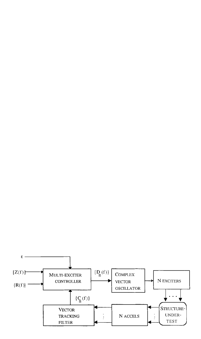
The overall block diagrams of the MIMO swept-sine control system and the
MIMO sweep-sine controller are shown in Figs. 27.13 and 27.14, respectively. As can
be seen in the block diagram of the overall system in Fig. 27.13, a vector-tracking fil-
ter subsystem plays the role of the time-to-frequency conversion in the DVCS. As
27.32 CHAPTER TWENTY-SEVEN
FIGURE 27.13 Overall multiexciter vibration control system.
8434_Harris_27_b.qxd 09/20/2001 11:51 AM Page 27.32
discussed in a previous section, tracking filters estimate the complex amplitude of
the sweeping sine-wave control-response signals, c
1
(t) through c
n
(t). The resulting
complex control-response vector, {C(f)}, is then compared by the DVCS with the
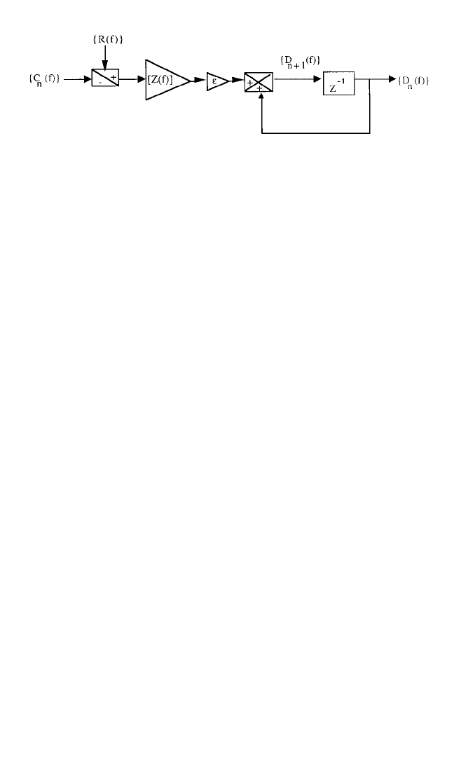
specified test reference-response vector, {R(f)}.The control-error vector is then mul-
tiplied by the impedance matrix, [Z(f)], to get the contribution of the control errors
at each control location to each drive signal sent to each exciter.A percentage of this
error, given by ε, is added to the previous complex-drive signal’s amplitude spectrum
to obtain the next drive signal’s vector spectrum amplitude, as shown in the multi-
exciter swept-sine controller block diagram in Fig. 27.14. This corrected drive signal,
with updated amplitude and relative phase, is then sent to the vector oscillator,
which plays the role of the frequency-to-time transformation subsystem within the
DVCS. It provides control of the amplitude of the output drive signals and the rela-
tive phase with respect to the modulating signal used by the vector-tracking filter
shown in Fig. 27.13. Each component of {C(f)} is an output of an individual tracking
filter, within the vector-tracking filter in Fig. 27.13 given by Fig. 27.6, which all use the
same modulating signal. There is also a common phase and frequency reference for
the drive signals generated by the complex vector oscillator in Fig. 27.13. The system
is driven as the frequency of the drive-signal vector is swept continuously through
the sweep range of the MIMO swept-sine wave test.
MIMO Transient/Shock. MIMO transient waveform control methods are an
extension of single-shaker transient/shock and MIMO swept-sine control methods
previously discussed. This type of control is used principally for seismic simulations.
The application uses shock response spectrum synthesis techniques to create the
waveforms that are to be used as the specified reference-response vector, {r(t)}. In
this case, the control process matches the specified shock response spectrum indi-
rectly by using waveform control to make the control response, {c(t)}, match {r(t)},
thereby indirectly matching the specified shock response spectrum. This vector of
waveforms, {r(t)}, typically consist of random transients that have been synthesized
such that each such transient matches a specified shock response spectrum to be
used as the spectral reference response for each control point, as discussed in the
section on shock response spectrum synthesis. In other applications, these transient
waveforms sometimes represent data that have been measured in the field. Many
times, they are actual earthquake time-domain response data, from remote sensors
that are located to measure an earthquake’s ground motion when and where it
occurs. The block diagram of this type of control system is similar to that of MIMO
sine. The predominant difference is that the time-to-frequency transformation is
accomplished by an FFT, with a frame size large enough to accommodate the tran-
sient, but still avoid circular convolution errors.
1
Spectral leakage errors (see Chap.
14) are mitigated by using windowing.
MIMO Long-Term Response Waveform Control. This application is an exten-
sion of MIMO transient waveform control discussed in the previous section.The pri-
APPLICATION OF DIGITAL COMPUTERS 27.33
FIGURE 27.14 Multiexciter swept-sine vibration control system.
8434_Harris_27_b.qxd 09/20/2001 11:51 AM Page 27.33