Heywood J.B. Internal Combustion Engines Fundamentals
Подождите немного. Документ загружается.

200
Experiment:
MBT
A
MBT
+
101
I
-
Calculated
Equivalence ratio
4
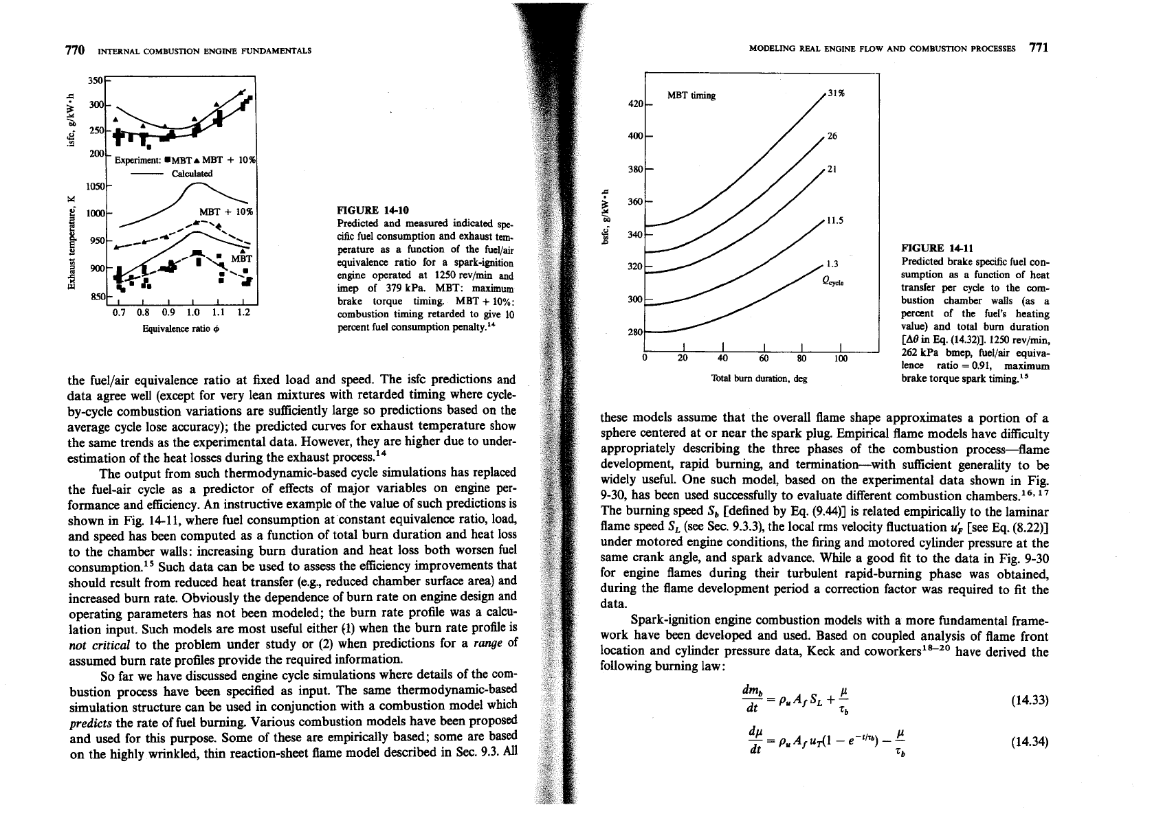
FIGURE
14-10
Predicted and measured indicated spe-
cific fuel consumption and exhaust tem-
perature
as
a function
of
the fuellair
equivalence ratio for a spark-ignition
engine operated at
1250
rev/min
and
imep
of
379
kPa.
MBT:
maximum
brake torque timing.
MBT
+
10%:
combustion timiig retarded to give
10
percent fuel consumption penalty.14
the fuellair equivalence ratio at fixed load and speed. The isfc predictions and
data agree well (except for very lean mixtures with retarded timing where cycle-
by-cycle combustion variations are sufficiently large so predictions based on the
average cycle lose accuracy); the predicted curves for exhaust temperature show
the same trends as the experimental data. However, they are higher due to under-
estimation of the heat losses during the exhaust process.14
The output from such thermodynamic-based cycle simulations has replaced
the fuel-air cycle as a predictor of effects of major variables on engine per-
formance and efficiency.
An
instructive example of the value of such predictions is
shown in Fig. 14-11, where fuel consumption at constant equivalence ratio, load,
and speed has been computed as a function of total bum duration and heat loss
to the chamber walls: increasing burn duration and heat loss both worsen fuel
wns~mption.'~ Such data can
be
used to assess the efficiency improvements that
should result from reduced heat transfer (e.g., reduced chamber surface area) and
increased bum rate. Obviously the dependence of burn rate on engine design and
operating parameters has not been modeled; the bum rate profile was a calcu-
lation input. Such models are most useful either
(1) when the burn rate profile is
not
critical
to the problem under study or
(2)
when predictions for a
range
of
assumed bum rate profiles provide the required information.
So far we have discussed engine cycle simulations where details of the com-
bustion process have
been
specified as input. The same thermodynamic-based
simulation structure can
be
used in conjunction with a combustion model which
predicts
the rate of fuel burning. Various combustion models have been proposed
and used for this purpose. Some of these are empirically based; some are based
on the highly wrinkled, thin reaction-sheet flame model described in
Sec. 9.3.
All
MODELING
REAL
ENGINE
FLOW
AND
COMBUSTION
PROCESSES
771
MBT timing
420
-
400-
380
-
m
0
20
40
60
80
100
Total bum duration, deg
FIGURE
14-11
Predicted brake spedic fuel con-
sumption
as
a function of heat
transfer per cycle to the com-
bustion chamber walls
(as
a
percent of the fuel's heating
value) and total bum duration
[A9
in
Eq.
(14.3211. 1250
rev/min,
262
kPa bmep, fuellair equiva-
lence ratio
=
0.91,
maximum
brake torque spark timing.I5
these models assume that the overall flame shape approximates a portion of a
sphere centered at or near the spark plug. Empirical flame models have difficulty
appropriately describing the three phases of the combustion process-flame
development, rapid burning, and termination-with sufficient generality to
be
widely useful. One such model, based on the experimental data shown in Fig.
9-30, has been used successfully to evaluate different combustion chambers.16*
l7
The burning speed
S,
[defined by
Eq.
(9.441 is related empirically to the laminar
flame speed
S,
(see Sec. 9.3.3), the local rms velocity fluctuation
u;
[see
Eq.
(8.22)]
under motored engine conditions, the firing and motored cylinder pressure at the
same crank angle, and spark advance. While a good fit to the data in Fig. 9-30
for engine flames during their turbulent rapid-buming phase was obtained,
during the flame development period a correction factor was required to fit the
data.
Spark-ignition engine combustion models with a more fundamental frame-
work have been developed and used. Based on coupled analysis of flame front
location and cylinder pressure data, Keck and
co~orkers'"~~ have derived the
following burning law
:
772
INTERNAL COMBUSTION ENGINE FUNDAMENTALS
MODELING
REAL
ENGINE
now
AND
COMBUSTION
PROCESSES
773
2.
Initially, as
t
-+
0,
-.
sb
+
SL (14.363)
3.
Quasi-steady state, dpldt
x
0,
.....
,
$
..
,
.:.,I,,
:..
;..:
....
.
..
..
Sb
X
UT
+
SL
(14.36~)
4.
Final burning stage after the flame front reaches the wall,
t
2
t,
(when
:I;::
.:
.
,
..
+.'
..
.
..
...
:
.
A
,
-,
01,
.,
......
.
..
.
. .
,.
..
..
.
IL
...
I,
~..
.
,
...
.
:.
-
litb
-
e-(r-tw)/~b
(14.36d)
mb(tw)
-
To apply Eqs. (14.33) and (14.34), the quantities u, and rb (or 1,
=
zbSJ
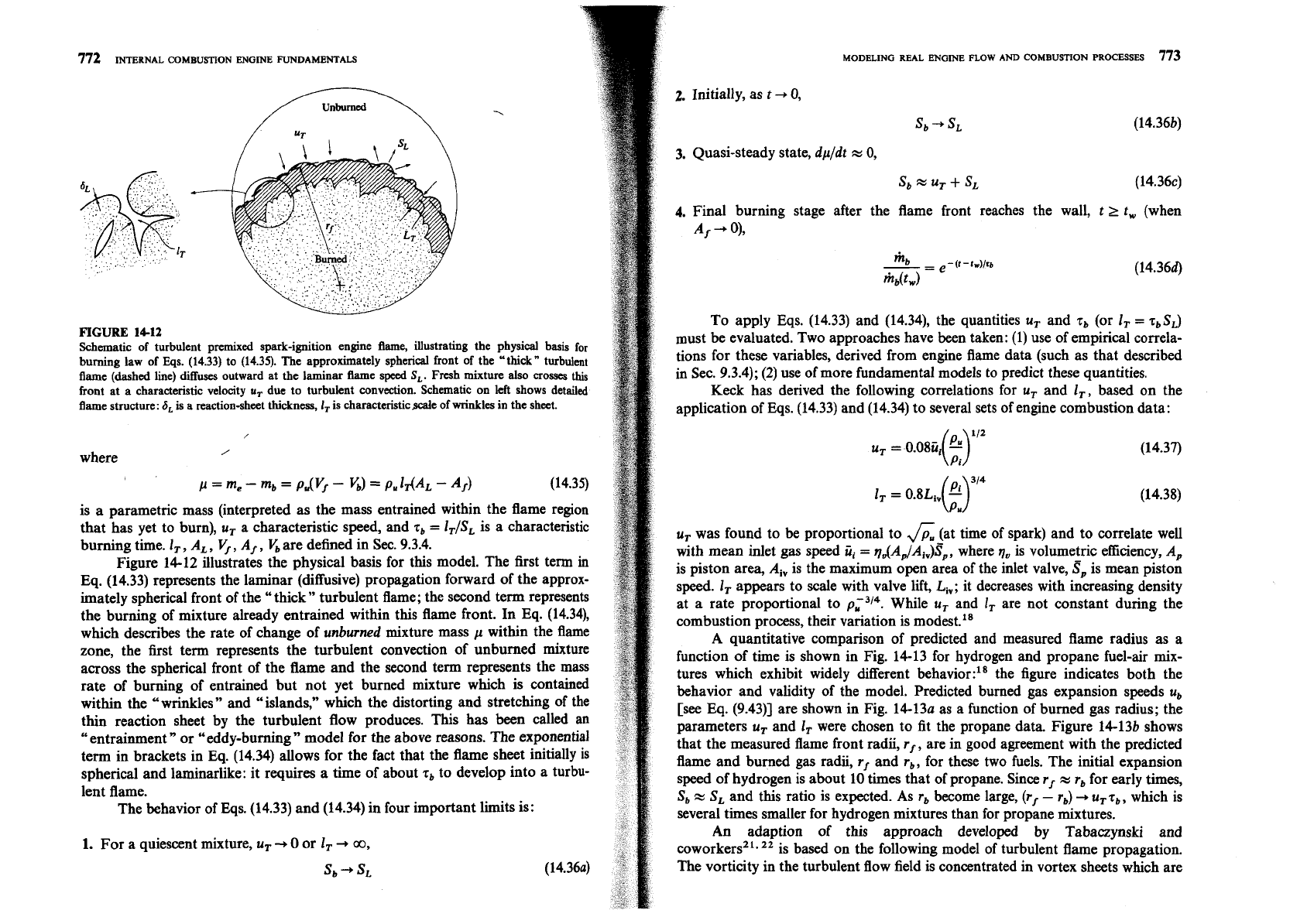
FIGURE
1412
Schematic of turbulent premixed spark-ignition engine flame, illustrating the physical basis for
must be evaluated. Two approaches have been taken:
(1)
use of empirical correla-
burning law of ~qs. (14.33) to (14.35). The approximately spherical front of the "thick" turbulent
tions for these variables, derived from engine flame data (such as that described
flame
(dashed line) diffuses outward at the laminar flame speed
S,.
Fresh
mixture
also
crosses
this
in Sec. 9.3.4); (2) use of more fundamental models to predict these quantities.
front at a characteristic velocity
u,
due to turbulent convection. Schematic on left shows detailed
Keck has derived the following correlations for u, and I,, based on the
flame structure:
6,
is a reactionsheet thickness,
I,
is characteristicscale of wrinkles in the sheet.
application of Eqs. (14.33) and (14.34) to several sets of engine combustion data:
/
/
u,
=
O.08tri
'
(9"'
(14.37)
where
p
=
me
-
mb
=
pNf
-
GI
=
pp,
MAL
-
A,)
1,
=
0.8Lh
-
(Y4
(14.38)
is a parametric mass (interpreted as the mass entrained within the flame region
that has yet to burn), u, a characteristic speed, and rb
=
lT/SL is a characteristic
u, was found
to
be proportional to
6
(at time of spark) and to correlate well
burning time.
I,,
A,,
5,
A,, bare defined in Sec. 9.3.4.
with mean inlet gas speed
ii,
=
q&AdAiv)SP, where
q,
is volumetric efficiency, A,
Figure 14-12 illustrates the physical basis for this model. The first term
in
is piston area, A, is the maximum open area of the inlet valve,
S,
is mean piston
Eq. (14.33) represents the laminar (diffusive) propagation forward of the approx-
speed. 1, appears to scale with valve lift, L,; it decreases with increasing density
imately spherical front of the "thick" turbulent flame; the second term represents
at a rate proportional to
pt3l4.
While u, and
1,
are not constant during the
the burning of mixture already entrained within this flame front. In Eq. (14.34),
combustion process, their variation is modest."
which describes the rate of change of unburned mixture mass
p
within the flame
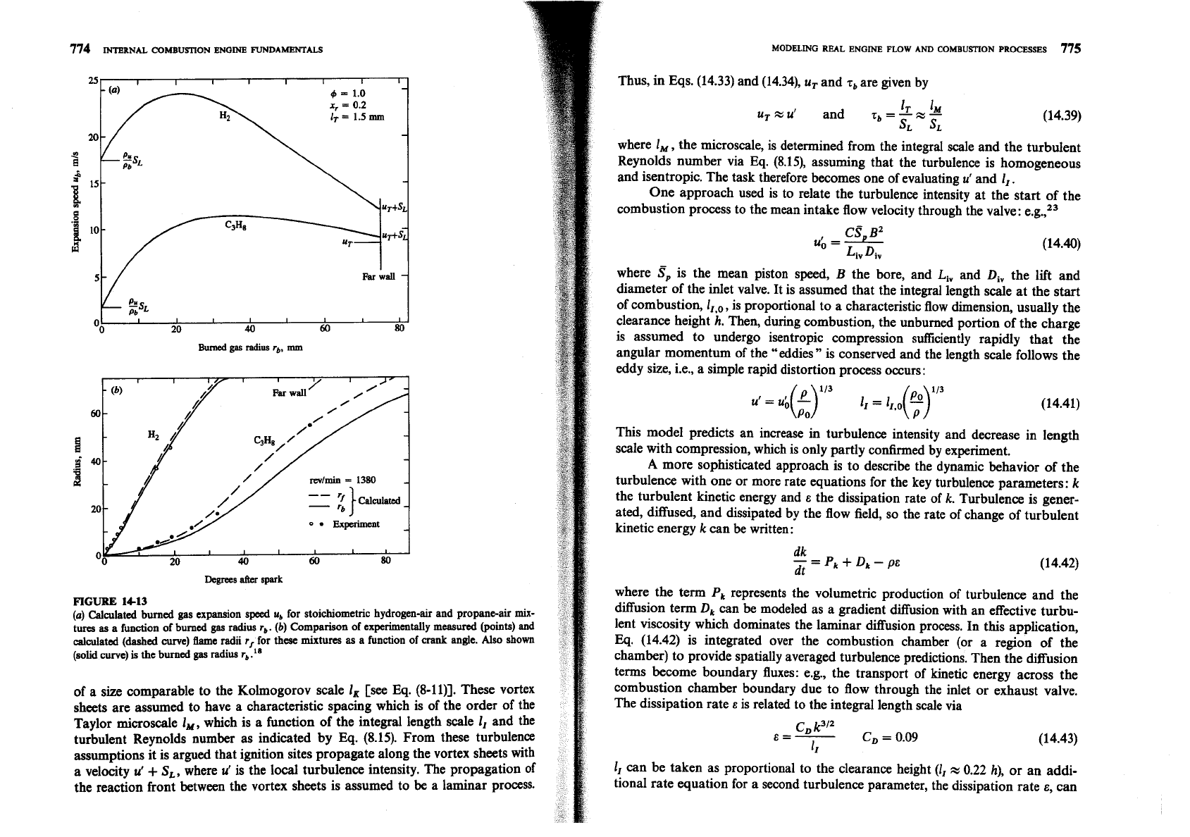
A quantitative comparison of predicted and measured flame radius as a
zone, the
&st term represents the turbulent convection of unburned mixture
function of time is shown in Fig. 14-13 for hydrogen and propane fuel-air
mix-
across the spherical front of the flame and the second term represents the mass
tures which exhibit widely different
behavior:18 the figure indicates both the
rate of burning of entrained but not yet burned mixture which is contained
behavior and validity of the model. Predicted burned gas expansion speeds
u,
within the "wrinkles" and "islands," which the distorting and stretching of the
[see Eq.
(9.43)] are shown in Fig. 14-13a as a function of burned gas radius; the
thin reaction sheet by the turbulent flow produces. This has
been called an
parameters
u, and
1,
were chosen to fit the propane data. Figure 14-13b shows
"entrainment
"
or "eddy-burning
"
model for the above reasons. The exponential
that the measured flame front radii, r,, are in good agreement with the predicted
term in brackets in Eq. (14.34) allows for the fact that the flame sheet initially is
flame and burned gas radii, rf and r,, for these two fuels. The initial expansion
spherical and laminarlike: it requires a time of about
r, to develop into a turbu-
speed of hydrogen is about 10 times that of propane. Since r,
x
rb for early times,
lent flame.
Sb
x
SL and this ratio is expected. As rb become large, (r,
-
r,)
-,
u, rb, which is
The behavior of Eqs. (14.33) and (14.34) in four important limits is:
several times smaller for hydrogen mixtures than for propane mixtures.
An
adaption of this approach developed by Tabaaynski and
1.
For a quiescent mixture,
u,
+
0 or
1,
-,
m,
coworkers2'.
22
is based on the following model of turbulent flame propagation.
sb
-,
SL
The vorticity in the turbulent flow field is concentrated in vortex sheets which are
774
INTERNAL
COMBUSTION
ENGME
FUNDAMENTALS
Far
wall
-
ESL
Oo
I I
I
I
I
I
I
20
40
60
80
Burned
gar
radius
rb,
mm
Degrees
affcr
spark
FIGURE
14-13
(a)
Calculated burned
gas
expansion speed
u,
for stoichiometric hydrogen-air and propaneair
mix-
tures
as
a
function of burned
gas
radius
r,.
(b)
Comparison of experimentally measured (points) and
calculated
(dashed
curve) flame radii
r,
for
these
mixtures
as
a function of
crank
angle. Also shown
(solid curve)
is
the burned
gas
radius
r,
.
''
of a size comparable to the Kolmogorov scale
1,
[see
Eq.
(8-ll)]. These vortex
sheets are assumed to have a characteristic spacing which is of the order of the
Taylor microscale I,, which is a function of the integral length scale I, and the
turbulent Reynolds number as indicated by
Eq.
(8.15). From these turbulence
assumptions it is argued that ignition sites propagate along the vortex sheets with
a velocity
u'
+
S,,
where
u'
is the local turbulence intensity. The propagation of
the reaction front between the vortex sheets is assumed to be a laminar process.
MODELING RWL
ENGINE
FLOW
AND
COMBUSTION
PROCESSES
775
Thus, in Eqs. (14.33) and (14.34),
uT
and
7,
are given by
where I,, the microscale, is determined from the integral scale and the turbulent
Reynolds number via
Eq.
(8.15), assuming that the turbulence is homogeneous
and isentropic. The task therefore becomes one of evaluating
u'
and
I,.
One approach used is to relate the turbulence intensity at the start of the
combustion process to the mean intake flow velocity through the valve: e.g.,23
where
S,
is the mean piston speed,
B
the bore, and
L,,
and
Div
the lift and
diameter of the inlet valve. It is assumed that the integral length scale at the start
of combustion,
IIp0
,
is proportional to a characteristic flow dimension, usually the
clearance height h. Then, during combustion, the unburned portion of the charge
is assumed to undergo isentropic compression sufficiently rapidly that the
angular momentum of the "eddies" is conserved and the length scale follows the
eddy size,
i.e., a simple rapid distortion process occurs:
This model predicts an increase in turbulence intensity and decrease in length
scale with compression, which is only partly confirmed by experiment.
A
more sophisticated approach is to describe the dynamic behavior of the
turbulence with one or more rate equations for the key turbulence parameters:
k
the turbulent kinetic energy and
e
the dissipation rate of
k.
Turbulence is gener-
ated, diffused, and dissipated by the flow field, so the rate of change of turbulent
kinetic energy
k
can be written:
where the term
P,
represents the volumetric production of turbulence and the
diffusion term
Dk
can
be
modeled as a gradient diffusion with an effective turbu-
lent viscosity which dominates the laminar diffusion process. In this application,
Eq. (14.42) is integrated over the combustion chamber (or a region of the
chamber) to provide spatially averaged turbulence predictions. Then the diffusion
terms become boundary fluxes:
e.g., the transport of kinetic energy across the
combustion chamber boundary due to flow through the inlet or exhaust valve.
The dissipation rate
E
is related to the integral length scale via
I,
can be taken as proportional to the clearance height (I,
x
0.22
h), or an addi-
tional rate equation for a second turbulence parameter, the dissipation rate
E,
can
776
INTERNAL
COMBUSTION
ENGINE
FUNDAMENTALS
Normal lift
0
114
normal
lii
-400
-200 0 200
400
Crank angle, deg
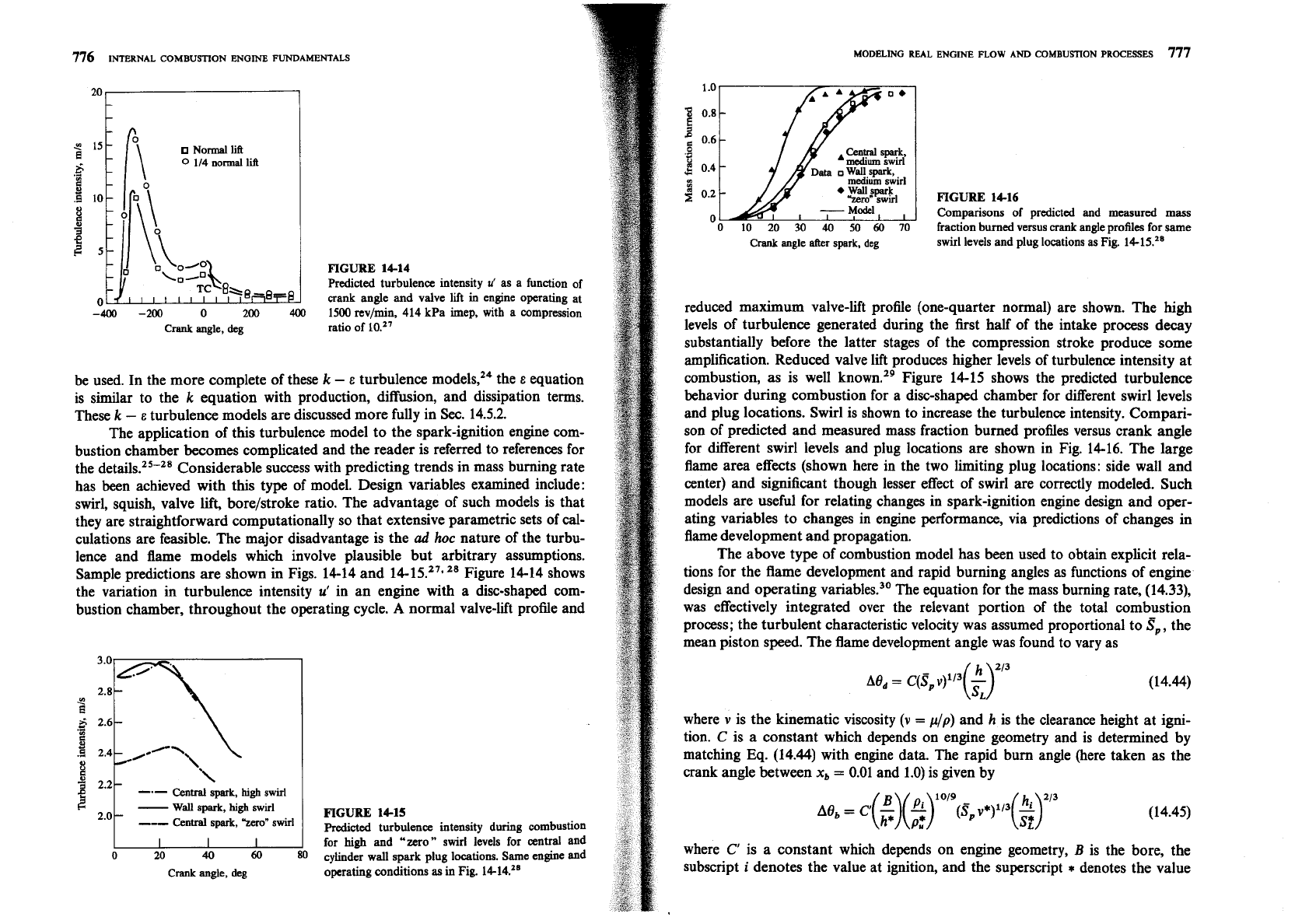
FIGURE
1414
Predicted turbulence intensity
u'
as a function of
crank angle and valve lift
in
engine operating at
1500 rev/min, 414 kPa imep, with a compression
ratio of
be used. In the more complete of these
k
-
e
turbulence models,24 the
E
equation
is similar to the
k
equation with production, diffusion, and dissipation terms.
These
k
-
E
turbulence models are discussed more fully in Sec. 14.5.2.
The application of this turbulence model to the spark-ignition engine com-
bustion chamber becomes complicated and the reader is referred to references for
the
detail^.^'-^'
Considerable success with predicting trends in mass burning rate
has been achieved with this type of model. Design variables examined include:
swirl, squish, valve lift, borelstroke ratio. The advantage of such models is that
they are straightforward computationally so that extensive parametric sets of
cal-
culations are feasible. The major disadvantage is the
ad
hoc
nature of the turbu-
lence and flame models which involve plausible but arbitrary assumptions.
Sample predictions are shown
in
Figs. 14-14 and 14-15.27.28 Figure 14-14 shows
the variation in turbulence intensity
u'
in an engine with a disc-shaped com-
bustion chamber, throughout the operating cycle.
A
normal valve-lift profile and
3.0
6
2.6
.-
a
:;I
8
-.-
\
Central
spark,
high
swirl
-
Wall
spark,
high
swirl
2.0
-
---
Central
spark,
'Zero"
swirI
,
0 20
40
60
80
Crank angle, deg
FIGURE
1415
Predicted turbulence intensity during combustion
for
high
and "zero" swirl levels for central and
cylinder wall spark plug locations.
Same
engine and
operating conditions
as
in Fig. 14-14.28
MODELING
REAL
ENGINE
FLOW
AND
COMBUSnON
PROCESSES
777
Crank
angle
after
spark,
deg
FIGURE
1416
Comparisons of predicted and measured mass
fraction burned versus crank angle profiles for same
swirl levels and plug locations as Fig. 14-15.28
reduced maximum valve-lift profile (one-quarter normal) are shown. The high
levels of turbulence generated during the first half of the intake process decay
substantially before the latter stages of the compression stroke produce some
amplification. Reduced valve lift produces higher levels of turbulence intensity at
combustion, as is well known.29 Figure 14-15 shows the predicted turbulence
behavior during combustion for a disc-shaped chamber for different swirl levels
and plug locations. Swirl is shown to increase the turbulence intensity. Compari-
son of predicted and measured mass fraction burned profiles versus crank angle
for different swirl levels and plug locations are shown in Fig. 14-16. The large
flame area effects (shown here in the two limiting plug locations: side wall and
center) and significant though lesser effect of swirl are correctly modeled. Such
models are useful for relating changes in spark-ignition engine design and oper-
ating variables to changes in engine performance, via predictions of changes in
flame development and propagation.
The above type of combustion model has been used to obtain explicit rela-
tions for the flame development and rapid burning angles as functions of engine
design and operating
variables.30 The equation for the mass burning rate, (14.33),
was effectively integrated over the relevant portion of the total combustion
process; the turbulent characteristic velocity was assumed proportional to
S,,
the
mean piston speed. The flame development angle was found to vary as
where
v
is the kinematic viscosity
(v
=
pip)
and
h
is the clearance height at igni-
tion.
C
is a constant which depends on engine geometry and is determined by
matching Eq. (14.44) with engine data. The rapid bum angle (here taken as the
crank angle between
x,
=
0.01 and 1.0) is given by
where
C'
is a constant which depends on engine geometry,
B
is the bore, the
subscript
i
denotes the value at ignition, and the superscript
*
denotes the value
at cylinder conditions where
xb
=
0.5. These expressions show reasonable agree-
ment with observed trends in
A8,
and
A8,.
14.43
Direct-Injection
Engine
Models
In direct-injection compression-ignition and stratifiedcharge engines, the liquid
fuel is injected into the cylinder as one or several jets just prior to ignition. In
large direct-injection compression-ignition engines, the air flow is essentially
quiescent. However, in medium and smaller size
DI
engines, the air flow is
usually swirling about the cylinder axis at up to 10 times the crankshaft rotation-
al speed; this air-flow pattern increases the rate of entrainment of air into the fuel
jet to increase the fuel-air mixing rate. Thus modeling of the ignition and com-
bustion processes for direct-injection types of engines is much more complex
than
for premixed-charge spark-ignition engines. The unsteady liquid-fuel jet
phenomena-atomization, liquid jet and droplet motion, fuel vaporization, air
entrainment, fuel-air mixing, and the ignition chemistry-all play a role in the
heat-release process (see Chap. 10). It is not yet possible to model all these pheno-
mena from a fundamental basis, even with the most sophisticated
fluid-dynamic-
based codes now available (see
Sec.
14.5), since many of these processes are not
yet adequately understood. However, models at various levels of detail and
empiricism have been developed and have proven useful in direct-injection diesel
and stratified-charge engine analysis. This section reviews the important features
of single-zone heat-release models and phenomenological jet-based combustion
models. Their relative simplicity and modest computer time requirements make
them especially useful for diesel cycle simulation and more complex engine
system studies.
Single-zone models assume that the cylinder contents can be adequately
described by property values representing the average state, and use one or more
algebraic formulas to define the heat-release rate. The functional forms of these
formulas are chosen to match experimentally observed heat-release profiles (see
Sec. 10.4.2). Coefficients in these formulas, which may vary with engine design
details and operating conditions, are determined empirically by fitting with data.
The phenomenological description of diesel combustion developed by Lyn (see
Sec. 10.3) comprises three primary phases: the ignition delay period, the premixed
fuel-burning phase, and the mixing-controlled fuel-burning phase. Ignition delay
correlations are reviewed in Sec. 10.6.6. Here models for the second and third
phases, when the major heat release occurs, are summarized (see Ref. 31 for
a
more extensive review). The attraction of the one-zone heat-release approach is
its simplicity: however, since it cannot fully describe the complex phenomena
which comprise the compression-ignition engine combustion process, substantial
empirical input must be used. Several one-zone heat-release models have been
proposed and used (e.g., Refs. 32 to 34). These use simple equations to describe
the rate of release of the fuel's energy, sometimes modeled on the presumed con-
trolling physical or chemical process and always calibrated by comparison with
data.
MODELING
REAL ENGINE
FLOW
AND
COMBUSTION PROCESSES
779
One extensively used model of this type developed by Watson et
~1.~~
is
especially appropriate for use in total diesel system simulations where the com-
bustion process details are not the primary focus. It is based on Lyn's description
of compression-ignition combustion-a rapid premixed burning phase followed
by a slower mixing controlled burning phase. The fraction of the injected fuel
that burns in each of these phases is empirically linked to the duration of the
ignition delay. One algebraic function is used to describe the premixed heat-
release phase and a second function to describe the mixing-controlled heat-
release phase. These two functions are weighted with a phase proportionality
factor,
fl,
which is largely a function of the ignition delay. Thus:
where
mf,,
is the mass of fuel burned,
m,,,
is the total fuel mass injected per cycle
per cylinder, and t' is time from ignition non-dimensionalized by total time
allowed for combustion
[
=
(t
-
tign)/Atcomb].t The premixed-burning function is
fi
=
1
-
(1
-
trK1)K2
(14.47)
and the mixing-controlled function is
f2
=
1
-
exp
(-
K, ttK4)
(14.48)
where K,, K,, K,, and K, are empirical coeficients. The proportionality factor
fl
is given by
where
4
is the overall fuellair equivalence ratio and
a,
b,
and
c
are empirical
constants.
Correlation with data from a typical turbocharged truck engine gave the
following values for K, to K,:
K,
=
2
+
1.25
x
10-'(qd
K,
=
5000
where z,, the ignition delay, is in milliseconds and
N,
engine speed, is in revo-
lutions per minute. It also gave these ranges for
a,
b,
c:jS
0.8
c
a
<
0.95; 0.25
c
b
c
0.45;
0.25
<
c
<
0.5
t
The combustion duration at
At,,,
is an arbitrary period within which combustion must
be
com-
pleted.
A
value of
125"
was
used
above.
INTERNAL
COMBUSTION
ENGINE
FUNDAMENTALS
Such single-zone heat-release models are useful because of their simplicity.
They obviously cannot relate engine design and operating variables explicitly to
the details of the combustion process. Experience indicates that those models
with only one function are not usually able to fit experimentally determined heat.
release profiles with sufficient accuracy. All single-zone heat-release models
should be checked against experimentally derived heat-release profiles, and recal.
ibrated if necessary, before being used for predictions.
Many thermodynamic-based direct-injection engine simulations incorpo-
rate an explicit model for each fuel spray which attempts to describe how the
spray develops with time. The spray starts out as a liquid fuel jet which then
vaporizes, entrains air and (later) burned gases. Mixture preparation can
be
limited by the availability of either fuel vapor or air, the former limited by
droplet evaporation and the latter by air entrainment. While there is evidence in
the literature to support both of these phenomena as rate-limiting, more recent
studies36 show that most (70 to
95
percent) of the injected fuel is in the vapor
phase at the start of combustion, whereas only 10 to
35
percent of the vaporized
fuel is mixed to within the combustion limits (equivalence ratio between 0.3 and
3). This suggests that the combustion process in typical heavy-duty
direct-
injection compression-ignition engines is mixing controlled rather than vapor-
ization controlled.
While spray geometry is an essential aspect of the fuel-air mixing process, it
may not be necessary to model the precise details of the actual configuration. For
the purpose of heat-release and emission analysis, it suffices in many phenomeno-
logical models to calculate the evolution of the fuel mass, composition, volume,
and temperature of critical regions of the spray based on a generic spray
geometry.
Alternate approaches attempt to provide a detailed structure for the
fuel spray to improve the modeling of air entrainment, effects of swirl/spray inter-
action, and heat transfer. The more commonly used approaches are illustrated in
Fig. 14-17.
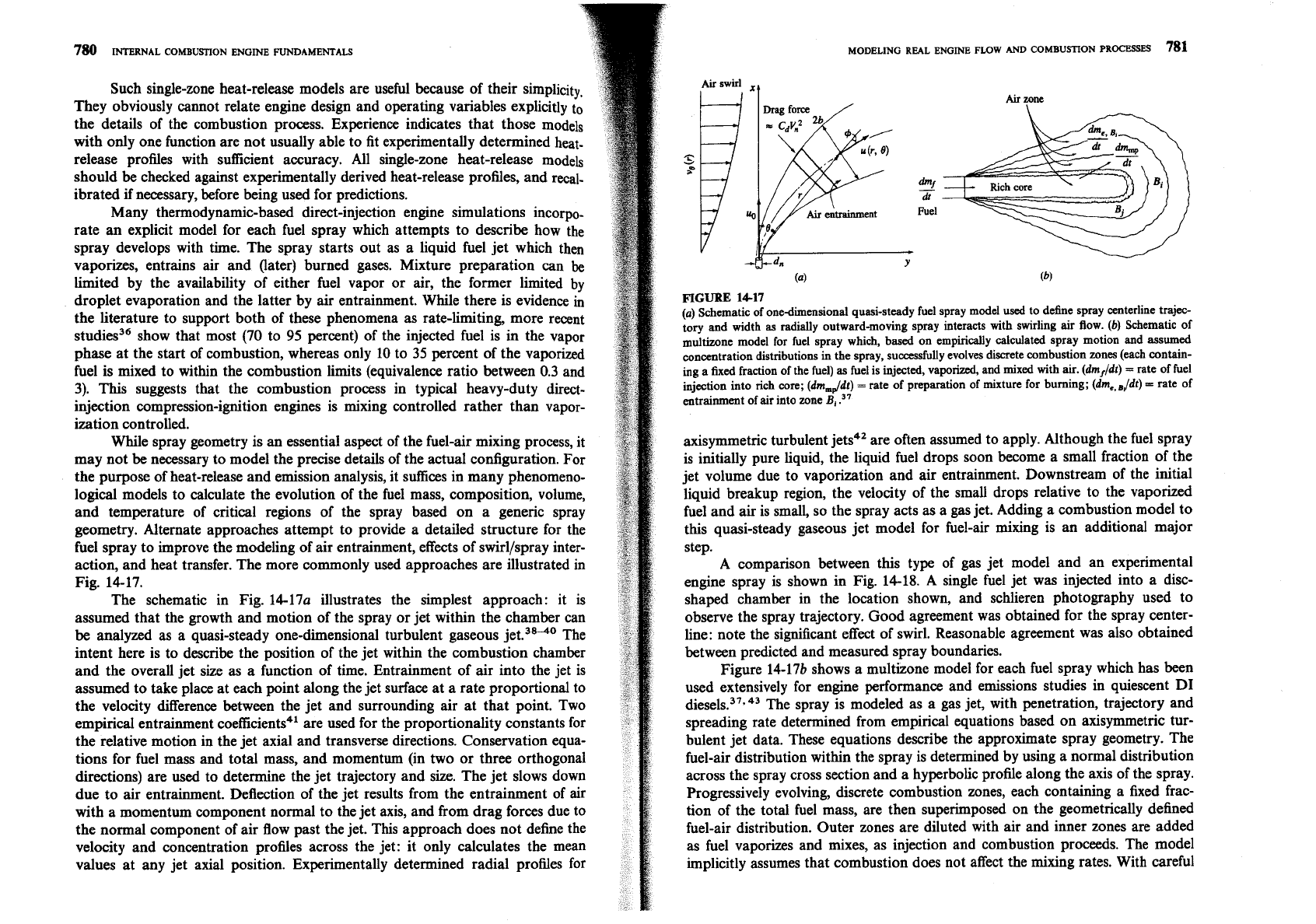
The schematic in Fig. 14-17a illustrates the simplest approach: it is
assumed that the growth and motion of the spray or jet within the chamber can
be analyzed as a quasi-steady one-dimensional turbulent gaseous
jet.3840 The
intent here is to describe the position of the jet within the combustion chamber
and the overall jet size as a function of time. Entrainment of air into the jet is
assumed to take place at each point along the jet surface at a rate proportional to
the velocity difference between the jet and surrounding air at that point. Two
empirical entrainment coefficients4' are used for the proportionality constants for
the relative motion in the jet axial and transverse directions. Conservation equa-
tions for fuel mass and total mass, and momentum (in two or three orthogonal
directions) are used to determine the jet trajectory and size. The jet slows down
due to air entrainment. Deflection of the jet results from the entrainment of air
with a momentum component normal to the jet axis, and from drag forces due to
the normal component of air flow past the jet. This approach does not define the
velocity and concentration
profiles across the jet: it only calculates the mean
values at any jet axial position. Experimentally determined radial profiles for
MODELING
REAL
ENGINE
FLOW
AND
COMBUSTION
PROCESSES
781
Aii
swirl
.,
d"'f
-
dt
Fuel
FIGURE
14-17
(a)
Schematic of onedimensional quasi-steady fuel spray model
used
to define spray centerline trajeo
tory and width
as
radially outward-moving spray interacts with swirling air Aow.
(b)
Schematic of
multizone model for fuel spray which, based on empirically calculated spray motion and assumed
concentration distributions in the spray, successfully evolves discrete combustion zones (each contain-
ing
a
fixed fraction of the fuel)
as
fuel is injected, vaporized, and mixed with air. (dmJ/dt)
=
rate of fuel
injection into
rich
wre; (dm,Jdt)
=
rate of preparation of mixture for burning; (dm,,
,Jdt)
=
rate of
entrainment of air into zone
B,
.37
axisymmetric turbulent jets4' are often assumed to apply. Although the fuel spray
is initially pure liquid, the liquid fuel drops soon become a small fraction of the
jet volume due to vaporization and air entrainment. Downstream of the initial
liquid breakup region, the velocity of the small drops relative to the vaporized
fuel and air is small, so the spray acts as a gas jet. Adding a combustion model to
this quasi-steady gaseous jet model for fuel-air mixing is an additional major
step.
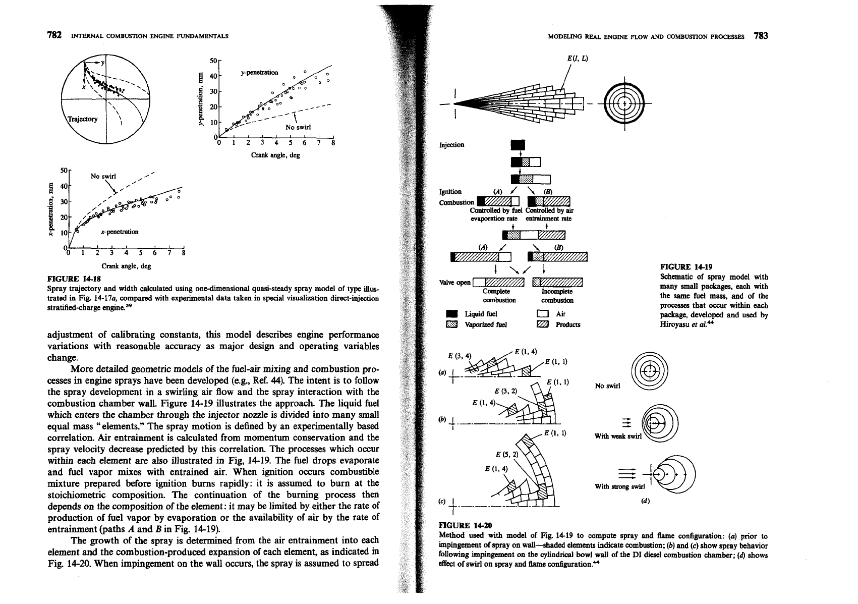
A comparison between this type of gas jet model and an experimental
engine spray is shown in Fig. 14-18. A single fuel jet was injected into a
disc-
shaped chamber in the location shown, and schlieren photography used to
observe the spray trajectory. Good agreement was obtained for the spray
center-
line: note the significant effect of swirl. Reasonable agreement was also obtained
between predicted and measured spray boundaries.
Figure 14-17b shows a multizone model for each fuel spray which has been
used extensively for engine performance and emissions studies in quiescent DI
die~els.~'.~~ The spray is modeled as a gas jet, with penetration, trajectory and
spreading rate determined from empirical equations based on axisyrnmetric tur-
bulent jet data. These equations describe the approximate spray geometry. The
fuel-air distribution within the spray is determined by using a normal distribution
across the spray cross section and a hyperbolic profile along the axis of the spray.
Progressively evolving, discrete combustion zones, each containing a fixed frac-
tion of the total fuel mass, are then superimposed on the geometrically defined
fuel-air distribution. Outer zones are diluted with air and inner zones are added
as fuel vaporizes and mixes, as injection and combustion proceeds. The model
implicitly assumes that combustion does not affect the mixing rates. With careful
V,,,,,,,,
O012345678
Crank
angle,
deg
FIGURE
14-18
Spray trajectory and width calculated using one-dimensional quasi-steady spray model of type illus-
trated in Fig.
14-17%
compared with experimental data taken in special visualization direct-injection
stratified-charge engine.39
adjustment of calibrating constants, this model describes engine performance
variations with reasonable accuracy as major design and operating variables
change.
More detailed geometric models of the fuel-air mixing and combustion pro-
cesses in engine sprays have been developed
(e.g., Ref.
44).
The intent is to follow
the spray development in a swirling air tiow and the spray interaction with the
combustion chamber wall. Figure 14-19 illustrates the approach. The liquid fuel
which enters the chamber through the injector nozzle is divided into many small
equal mass "elements." The spray motion is defined by an experimentally based
correlation. Air entrainment is calculated from momentum conservation and the
spray velocity decrease predicted by this correlation. The processes which occur
within each element are also illustrated in Fig, 14-19. The fuel drops evaporate
and fuel vapor mixes with entrained air. When ignition occurs combustible
mixture prepared before ignition burns rapidly: it is assumed to burn at the
stoichiometric composition. The continuation of the burning process then
depends on the composition of the element: it may
be
limited by either the rate of
production of fuel vapor by evaporation or the availability of air by the rate of
entrainment (paths
A
and B in Fig. 14-19).
The growth of the spray is determined from the air entrainment into each
element and the combustion-produced expansion of each element, as indicated in
Fig. 14-20. When impingement on the wall occurs, the spray is assumed to spread
--
~,,us+jon
Controlled
by
fuel
Coatrolled
by
air
FIGURE
14-19
Schematic of spray model with
many small packages, each with
the same fuel mass, and of the
processes that
occur within each
package, developed and
used
by
Hiroyasu
et
aLU
No swirl
@
z@
With
weak swirl
With
strong swirl
FIGURE
14-20
Method
used
with model of Fig.
1419
to compute spray and
flame
configuration:
(a)
prior
to
impingement of spray on wall-shaded elements indicate combustion;
(b)
and
(c)
show spray behavior
following impingement on the cylindrical bowl wall of the
Dl
diesel combustion chamber;
(d)
shows
effect
of
swirl on spray and flame configuration."

INTERNAL COMBUSTION ENGINE FUNDAMENTALS
along the wall with a constant thickness as shown in Fig. 14-20. When the per-
iphery of the spray reaches that of a neighboring spray the sideways growth
of
the spray is then prevented and the thickness of the elements along the wall
increases. Swirl effects are calculated from tangential momentum considerations.
Each annular cone ring element is shifted sideways by the swirl as indicated in
Fig. 14-20.
The heat-release rate in the combustion chamber is obtained by smng
up the heat release in each element. Nitric oxide and soot formation calculations
are based on the time histories of temperature, vaporized fuel, air and com-
bustion products in each element. The overall structure of this particular
corn-
plete diesel engine performance and emissions model is indicated in Fig. 14-21
:
it
is typical of the type of compression-ignition engine simulation used to study
engine performance and emissions. Figure 14-22 shows an example of the output
from the above model. The injection rate diagram, the assumed Sauter
mean
drop size of the spray, and the air swirl determine the spray development which
leads to the heat-release rate predictions. This determines the cylinder pressure
profile. Predicted engine performance results show reasonable but not precise
agreement with experimental data. That is not surprising given the complexity
of
the phenomena being modeled. A review of these types of jet models is given by
Hiroya~u.~~
14.4.4
Prechamber
Engine
Models
Small high-speed compression-ignition engines use an auxiliary combustion
chamber, or prechamber, to achieve adequate fuel-air mixing rates. The precham-
ber is connected to the main combustion chamber above the piston via a nozzle,
passageway, or one or more orifices (see Sea. 1.8, 8.5, and 10.2.2). Auxiliary
chambers are sometimes used in spark-ignition engines, also. The plasma and
flame-jet ignition systems described in Sec.
9.5.3
enclose the spark plug in a cavity
or small prechamber which connects to the main chamber via one or more ori-
fices. The function of the prechamber is to increase the initial growth rate of the
flame. Combustion in the main chamber is initiated by one or more flame jets
emanating from the prechamber created by the ignition process and subsequent
energy release within the prechamber. If the mixture within the prechamber is
richer than in the main chamber (due to fuel injection or a separate prechamber
intake
valve--see Sec.
1.9)
these are called stratified-charge engines.
The additional phenomena which these prechambers introduce beyond
those already present in conventional chamber engines are: (1) gas flows through
the nozzle or orifice between the main chamber and prechamber due to piston
motion; (2) gas flows between these chambers due to the combustion-generated
pressure rise;
(3)
heat is transferred to the nozzle or passageway walls due to
these flows. The first of these phenomena results in nonuniform composition and
temperature distributions between the main and prechamber due to gas displace-
ment primarily during compression, and determines the nature of the flow field
within the prechamber toward the end of compression just prior to combustion.
Specifications of engine and operating conditions
Equilibrium
products
FIGURE
1421
.Soot
formation
and
oxidation Structure of thermodynamic-
based
Dl
diesel simulation for
predicting engine performance
and emissions. Simulation incor-
porates spray model of type illus-
trated in Figs.
14-19
and
14-20!'
Crank
angle
0,
deg
FIGURE
1422
Fuel-injection rate, heat-release rate profile, and cylinder pressure predicted with thermodynarnic-
based
DI
diesel simulation
with
spray and combustion model of
type
shown
in
Fig.
14-21.4s
The second phenomena controls the rate of energy release in the main chamber.
The heat losses in the passageway and to the additional chamber surface area
of
the prechamber designs relative to conventional open chambers result in
decreased engine performance and efficiency. Thus the prechamber concept ad&
additional complexity to the engine processes that must be modeled to predict
engine behavior.
The following variables are important to prechamber engine performance
and emissions characteristics, in addition to the design and operating variables
which govern singlechamber engine behavior: prechamber geometry--size,
shape, flow area and shape of connecting
passageway(s); prechamber location in
relation to main chamber geometry; geometry and timing of any auxiliary pre-
chamber valve; fuel metering strategy in prechamber compression-ignition or
stratified-charge engine. Thermodynamic-based models have been developed and
used to examine the overall impact of these variables (see Ref. 47). Computational
fluid dynamic models (see Sec. 14.5 and Fig. 8-26) have also been used to examine
specific prechamber engine flow and combustion processes.
Useful predictions of fuel,
air,
and residual gas distributions and the corre-
sponding temperature within the prechamber and main chamber can be obtained
with simple gas displacement models. Only during combustion is the pressure
difference across the nozzle or orifice sufficiently large in magnitude for its model-
ing to be essential; the assumption of uniform pressure during compression, the
critical process for determining conditions just prior to combustion, introduces
little error into calculations of the flows between the chambers. Section 8.5
develops the appropriate equations for these piston-motion driven gas displace-
ments. Use of the conservation equations for an open system, for total mass, fuel
mass, residual gas, and energy given in
Sec. 14.2, for the main chamber and the
prechamber, then give the mean composition and temperature variation in each
chamber as a function of time due to this flow. Figure 8-25 illustrates the mean
composition variation in the prechamber that results during the compression
stroke of a three-valve stratifiedcharge engine.
During combustion, the pressure difference across the connecting passage-
way or orifice is the driving force for the flow between chambers. Since com-
bustion starts in the prechamber, the initial flow is into the main chamber; later,
as the heat release in the main chamber becomes dominant, the flow may reverse
direction and be into the prechamber. In thermodynamic-based models, the
equations for one-dimensional quasi-steady ideal gas flow through a restriction
given in App. C are used to relate these flows to the pressure difference between
the two chambers. Open-system conservation equations are again used to calcu-
late mean properties in each chamber.
Combustion models used are either empirically based
[e.g., using specified
heat-release or mass burning rates such as Eq. (14.32)48] or are developed from
direct-injection compression-ignition engine models with spray evaporation, fuel-
air mixing, and ignition delay processes explicitly included?' Because of the com-
plexity of these processes
in the prechamber engine geometry, substantial
simplifying assumptions and empiricism must be used.
MODELING REAL
ENGINE
FLOW
AND COMBUSTION PROCESSES
787
Heat transfer to the passageway and chamber walls is affected by the flows
between the chambers: high velocities within the passageway result in high heat-
transfer rates to the passageway walls, and the vigorous flows set by the passage-
way exit flow entering the prechamber or the main chamber increase
heat-transfer rates to the walls of these chambers. The standard engine heat-
transfer correlations which relate the heat-transfer coefficient to mean flow field
variables via Nusselt-Reynolds number relationships (see
Sec. 12.4) are normally
used to describe these heat-transfer processes. The length scales are chosen to
match the prechamber or main chamber or passageway dimensions. The charac-
teristic velocities in these relationships are equated with velocities which are rep-
resentative of the flow in each of these regions at the relevant time in the engine
operating
cycle.50.
The utility of the more sophisticated of these prechamber engine per-
formance and emissions models is illustrated by the sample results shown in Fig.
14-23. This simulation of the indirect-injection compression-ignition engine's flow
and combustion processes describes, through the use of stochastic mixing models,
the development of the
fuellair ratio distribution and fuel-energy release distribu-
tion, and hence the development of the gas pressure and gas temperature dis-
tribution, within the prechamber and main chambers of the engine. With the
(nonuniform) gas composition and state defined, the models for NO formation
described in
Sec. 11.2.1 was used to predict NO, emissions. The approaches used
to describe the evolution of the prechamber, main chamber, and passageway con-
tents are summarized in Fig.
14-23a.
The cylinder contents were divided up into a large number of elements.
Pairs of elements are selected at random to undergo "turbulent mixing" inter-
actions at a frequency related to the turbulence in each region. Rate
processes-
evaporation, ignition, NO formation, etc.-proceed within each element between
these mixing interactions. Figure 14-23b shows sample results. At about TC, after
some of the injected fuel has evaporated and the ignition delay is over, com-
bustion starts in the prechamber and the prechamber pressure
p,
rises above the
main chamber pressure
p,.
This forces air, fuel, and burned gases to flow from
the prechamber into the main chamber; fuel and rich products can now mix with
air and burn in the main chamber. NO starts to form in each mass element, once
it burns, at a rate dependent on each element's composition and state. Most of
the NO forms within the prechamber and then flows into the main chamber as
the expansion process proceeds. The attractive feature of this type of emission
calculation is that the kinetically controlled NO formation calculations are
based directly on local gas composition and temperature in a manner that
approximately simulates the mean and turbulent
nonuniformities in these vari-
ables. Predictions of engine operation and emissions showed good agreement
with
data."
Fluid-dynamic-based models have been used to study fluid flow, com-
bustion, and pressure wave phenomena in prechamber engines. Section 14.5
reviews this type of engine model. Additional details of these applications can be
found
in
Refs. 53 and 54.

Injection:
add
liquid
fucl
el~lents
partially
stimd
reactor
Elements
transfermi
through pssgnvay:
flow
reariaion
wtth
heat
transfer
partially
stimd
reactor
PartiaUy
stimd
reactom
contain
many
equal
mass
elements.
Thesc
elements
may be
air
(plus
residual),
Liquid
fuel,
unburned
mixture
(fuel
vapor,
air,
burned
gas),
and
burned
mixture
MODELING
REAL
ENGINE
FLOW
AND
COMBUSTION
PROCESSES
789
14.4.5
Molticylinder
and
Complex Engine
System Models
The models discussed in the previous parts of Sec. 14.4 focus on the processes
occurring within
each
cylinder of an internal combustion engine. Most engines
are multicylinder engines and the individual cylinders interact via the intake and
exhaust manifolds. Also, many engine systems are more complex: internal com-
bustion engines can be supercharged, turbocharged, or turbocompounded, and
the manifolds then connect to the atmosphere via compressors or turbines (see
Fig. 6-37 and
Sec. 6.8). Thermodynamic-based simulations of the relevant engine
processes, constructed from the types of model components already described,
prove extremely useful for examining the behavior of these more complex engine
systems. By describing the mass and energy flows between individual components
and cylinders of such systems throughout the engine's operating cycle, the total
system preformance can be predicted. Such models have been used to examine
steady-state engine operation at constant load and speed (where time-varying
conditions in the manifolds due to individual cylinder filling and emptying events
affect multicylinder engine behavior), and how the total system responds to
changes in load and speed during engine transients.
The block diagram of a turbocharged and turbocompounded diesel engine
system in Fig. 14-24 illustrates the interactions between the system components.
By describing the mass and energy flows between components and the heat and
,-------P-
work transfers within each component, total system behavior can
be
studied. In
such engine simulations, the reciprocator cylinders, the intake manifold, and the
various sections of the exhaust system are treated as connected open systems.
The flows into and out of these volumes are usually analyzed using the quasi-
FIGURE
14-23
steady emptying and filling approach described in Sec. 14.3.3, using the open-
10
TC
(a)
Schematic of
ID1
diesel
system conservation equations of Sec. 14.2. The reciprocator cycle is treated as a
engine illustrating how stochastic
sequence of processes within each cylinder: intake, compression, combustion
100
1
mixing models are applied to
(including expansion), and exhaust. These are modeled using the approaches
prechamber, main chamber, and
'
passageway to simulate turbulent
described previously in Secs. 14.4.1 to 14.4.4. Heat transfer has, of course, an
mixing processes and pressure-
important effect on the in-cylinder processes. It also is important in the exhaust
driven flows.
(b)
Example of
system since the performance of the turbocharger turbine and of any com-
sjmulation predictions though
pounded turbine depends on the gas state at the turbine inlet. The performance
1
&e engine's operating cycle.
of the turbomachinery components is normally defined by maps that interrelate
O
Shown are prechamber and main
g
chamber pressures, prechamber
efficiency, pressure ratio, mass flow rate, and shaft speed for each component
(see
a
and main chamber average
gas
Secs. 6.8.2 to 6.8.4). Special provisions are usually required in the logic of the
2
temperatures; fuel mass
injected,
turbomachinery map interpolation routines to avoid problems with the compres-
---__
evaporated, and burned in pre-
sor surge and turbine choking operating limits of these devices.
M~
rim
~0~
lm
1
mmber
and
main
cham^
When the reciprocator is coupled with turbomachinery its manifolds no
200
.g
average
NO
concentration
in
.--
each chamber (and total) in ppm
longer connect directly with the atmosphere: matching procedures are required
-
---
0
by volume and
mas
weight4
to ensure that the pressure levels and mass flow rates of the compressor and
TC
20
40
60
80
ppm (mass in chamber
x
NO
turbines match with those of the engine. The following matching process is
Crank
angle, deg
concentration in chamberltotal
typical of those used for turbocharged engines (one compressor and one turbine
(b)
mass
in
~ylinder).'~
only). At a given time, the values of the variables describing the state of the
