Hibbeler R.C. Structural Analysis
Подождите немного. Документ загружается.


620 APPENDIX AMATRIX ALGEBRA FOR S TRUCTURAL A NALYSIS
A
Rather than using Eqs. A–11, it is perhaps easier to realize that the
evaluation of a second-order determinant can be performed by
multiplying the elements of the diagonal, from top left down to right, and
subtract from this the product of the elements from top right down to
left, i.e., follow the arrow,
Consider next the third-order determinant
Using Eq. A–11, we can evaluate using the elements either along the
top row or the first column, that is
As an exercise try to evaluate using the elements along the second row.
A.4 Inverse of a Matrix
Consider the following set of three linear equations:
which can be written in matrix form as
(A–12)
(A–13)Ax = C
C
a
11
a
12
a
13
a
21
a
22
a
23
a
31
a
32
a
33
SC
x
1
x
2
x
3
S= C
c
1
c
2
c
3
S
a
31
x
1
+ a
32
x
2
+ a
33
x
3
= c
3
a
21
x
1
+ a
22
x
2
+ a
23
x
3
= c
2
a
11
x
1
+ a
12
x
2
+ a
13
x
3
= c
1
ƒ
D
ƒ
= 114 - 02- 416 - 02- 1118 + 22=-40
D = 11-12
1 + 1
`
26
02
`
+ 41-12
2 + 1
`
3 -1
02
`
+ 1-121-12
3 + 1
`
3 -1
26
`
= 114 - 02- 318 + 62- 110 + 22=-40
D = 1121-12
1 + 1
`
26
02
`
+ 1321-12
1 + 2
`
46
-12
`
+ 1-121-12
1 + 3
`
42
-10
`
ƒ
D
ƒ
ƒ
D
ƒ
=
3
13-1
42 6
-10 2
3
D =
`
35
-12
`
= 3122- 51-12= 11
N

A.4 INVERSE OF A MATRIX 621
A
One would think that a solution for x could be determined by dividing C
by A; however, division is not possible in matrix algebra. Instead, one
multiplies by the inverse of the matrix. The inverse of the matrix A is
another matrix of the same order and symbolically written as It has
the following property,
where I is an identity matrix. Multiplying both sides of Eq. A–13 by
we obtain
Since we have
(A–14)
Provided can be obtained, a solution for x is possible.
For hand calculation the method used to formulate can be
developed using Cramer’s rule. The development will not be given here;
instead, only the results are given.* In this regard, the elements in the
matrices of Eq. A–14 can be written as
(A–15)
Here is an evaluation of the determinant of the coefficient matrix A,
which is determined using the Laplace expansion discussed in Sec. A.3.
The square matrix containing the cofactors is called the adjoint matrix.
By comparison it can be seen that the inverse matrix is obtained from
A by first replacing each element by its cofactor then transposing
the resulting matrix, yielding the adjoint matrix, and finally multiplying the
adjoint matrix by
To illustrate how to obtain numerically, we will consider the
solution of the following set of linear equations:
(A–16)
Here
A = C
1 -11
-111
12-2
S
x
1
+ 2x
2
- 2x
3
= 5
-x
1
+ x
2
+ x
3
=-1
x
1
- x
2
+ x
3
=-1
A
-1
1>
ƒ
A
ƒ
.
C
ij
,a
ij
A
-1
C
ij
ƒ
A
ƒ
C
x
1
x
2
x
3
S=
1
ƒ
A
ƒ
C
C
11
C
21
C
31
C
12
C
22
C
32
C
13
C
23
C
33
SC
c
1
c
2
c
3
S
x = A
-1
C
A
-1
A
-1
x = A
-1
C
A
-1
Ax = Ix = x,
A
-1
Ax = A
-1
C
A
-1
,
AA
-1
= A
-1
A = I
A
-1
.
*See Kreyszig, E., Advanced Engineering Mathematics, John Wiley & Sons, Inc., New York.

622 APPENDIX AMATRIX ALGEBRA FOR S TRUCTURAL A NALYSIS
A
The cofactor matrix for A is
Evaluating the determinants and taking the transpose, the adjoint
matrix is
Since
The inverse of A is, therefore,
Solution of Eqs. A–16 yields
Obviously, the numerical calculations are quite expanded for larger
sets of equations. For this reason, computers are used in structural
analysis to determine the inverse of matrices.
x
3
=-
1
6
[1-321-12+ 1-321-12+ 102152] =-1
x
2
=-
1
6
[1-121-12+ 1-321-12+ 1-22152] = 1
x
1
=-
1
6
[1-421-12+ 01-12+ 1-22152] = 1
C
x
1
x
2
x
3
S=-
1
6
C
-40-2
-1 -3 -2
-3 -30
SC
-1
-1
5
S
A
-1
=-
1
6
C
-40-2
-1 -3 -2
-3 -30
S
A =
†
1 -11
-111
12-2
†
=-6
C
T
= C
-40-2
-1 -3 -2
-3 -30
S
C = F
`
1
2
1
-2
`
-
`
-1
1
1
-2
``
-1
1
1
2
`
-
`
-1
2
1
-2
``
1
1
1
-2
`
-
`
1
1
-1
2
`
`
-1
1
1
1
`
-
`
1
-1
1
1
``
1
-1
-1
1
`
V

A.5 THE GAUSS METHOD FOR SOLVING SIMULTANEOUS EQUATIONS 623
A
A.5 The Gauss Method for Solving
Simultaneous Equations
When many simultaneous linear equations have to be solved, the Gauss
elimination method may be used because of its numerical efficiency.
Application of this method requires solving one of a set of n equations
for an unknown, say in terms of all the other unknowns,
Substituting this so-called pivotal equation into the remaining equations
leaves a set of equations with unknowns. Repeating the
process by solving one of these equations for in terms of the
remaining unknowns forms the second pivotal equation.
This equation is then substituted into the other equations, leaving a set
of equations with unknowns. The process is repeated until
one is left with a pivotal equation having one unknown, which is then
solved. The other unknowns are then determined by successive back
substitution into the other pivotal equations.To improve the accuracy of
solution, when developing each pivotal equation one should always select
the equation of the set having the largest numerical coefficient for the
unknown one is trying to eliminate. The process will now be illustrated by
an example.
Solve the following set of equations using Gauss elimination:
(A–17)
(A–18)
(A–19)
We will begin by eliminating The largest coefficient of is in
Eq. A–19; hence, we will take it to be the pivotal equation. Solving for
we have
(A–20)
Substituting into Eqs. A–17 and A–18 and simplifying yields
(A–21)
(A–22)
Next we eliminate Choosing Eq. A–21 for the pivotal equation since
the coefficient of is largest here, we have
(A–23)
Substituting this equation into Eq. A–22 and simplifying yields the final
pivotal equation, which can be solved for This yields
Substituting this value into the pivotal Eq. A–23 gives Finally,
from pivotal Eq. A–20 we get x
1
= 0.75.
x
2
= 0.25.
x
3
= 0.75.x
3
.
x
2
= 0.727 - 0.636x
3
x
2
x
2
.
1.5x
2
- 0.5x
3
= 0
2.75x
2
+ 1.75x
3
= 2
x
1
= 1 + 1.25x
2
- 0.75x
3
x
1
,
x
1
x
1
.
4 x
1
- 5x
2
+ 3x
3
= 4
2 x
1
- x
2
+ x
3
= 2
-2x
1
+ 8x
2
+ 2x
3
= 2
n - 3n - 3
x
n
Á ,x
4
,x
3
,
n - 2x
2
n - 1n - 1
x
n
.Á ,x
3
,x
2
,x
1
,

624 APPENDIX AMATRIX ALGEBRA FOR S TRUCTURAL A NALYSIS
A
A–1. If and , determine
and .
A–2. If and
,
determine and .
A–3. If and , determine AB.
*A–4. If and , determine AB.
A–5. If and , determine AB.
A–6. If and , show that
.
A–7. If , determine .
A–8. If , determine .
A–9. If , determine .
A–10. If and ,
determine AB.
A–11. If and ,
determine AB.
B = C
2
5
-1
SA = c
25-1
32 5
d
B = C
2
0
-1
SA = c
560
-123
d
AA
T
A = c
28
-15
d
AA
T
A = c
25
8 -1
d
A + A
T
A = C
236
592
-102
S
(A + B)
T
= A
T
+ B
T
B = C
-1
4
4
SA = C
2
5
6
S
B = [4 6 -5]A = C
2
-5
6
S
B = c
62
5 -1
dA = c
63
42
d
B = c
4 -1
2 -2
dA = [2 5]
A - 2B3A - 2B
B = C
64-3
32-2
51 6
SA = C
35-2
431
1 -17
S
A + 3B2A - B
B = C
-12
58
-21
SA = C
36
27
4 -2
S
*A–12. If and
,
determine AB.
A–13. Show that the distributive law is valid, i.e.,
if , ,
.
A–14. Show that the associative law is valid, i.e.,
, if , ,
.
A–15. Evaluate the determinants and .
*A–16. If , determine
A–17. If , determine
A–18. Solve the equations ,
, using the
matrix equation .
A–19. Solve the equations in Prob. A–18 using the Gauss
elimination method.
*A–20. Solve the equations ,
, using the matrix
equation .
A–21. Solve the equations in Prob. A–20 using the Gauss
elimination method.
x = A
-1
C
x
1
- x
2
- x
3
= 1x
1
- x
2
+ x
3
=-1
x
1
+ 2x
2
- 2x
3
= 5
x = A
-1
C
x
1
- 2x
2
+ x
3
= 2-5x
1
+ 4x
2
+ 3x
3
= 4
4x
1
+ x
2
+ x
3
=-1
A
-1
.A = C
357
4 -12
031
S
A
-1
.A = c
25
4 -1
d
3
572
182
-140
3
2
43
-16
2
C = [2 -13]
B = C
1
-1
4
SA = c
251
- 560
dA(BC) = (AB)C
C = C
4
2
1
S
B = C
2
-1
0
SA = c
42-1
35 6
dA(B + C) = AB + AC
B = C
2 -1 -1
325
246
SA = C
65-1
03 2
21 4
S
PROBLEMS

APPENDIX
B
625
General Procedure
for Using Structural
Analysis Software
Popular structural analysis software programs currently available, such as
STAAD, RISA, SAP, etc. are all based on the stiffness method of matrix
analysis, described in Chapters 13 through 15.* Although each program has
a slightly different interface, they all require the operator to input data
related to the structure.
A general procedure for using any of these programs is outlined below.
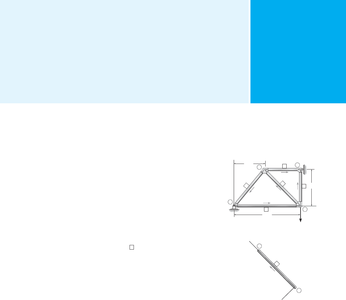
Preliminary Steps. Before using any program it is first necessary
to numerically identify the members and joints, called nodes, of the
structure and establish both global and local coordinate systems in order
to specify the structure’s geometry and loading. To do this, you may want
to make a sketch of the structure and specify each member with a
number enclosed within a square, and use a number enclosed within a
circle to identify the nodes. In some programs, the “near” and “far” ends
of the member must be identified. This is done using an arrow written
along the member, with the head of the arrow directed toward the far
end. Member, node, and “direction” identification for a plane truss,
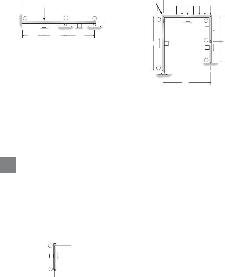
beam, and plane frame are shown in Figs. B–1, B–2, and B–3. In Fig. B–1,
node ➁ is at the “near end” of member
4
and node ➂ is at its “far end.”
These assignments can all be done arbitrarily. Notice, however, that the
nodes on the truss are always at the joints, since this is where the loads
are applied and the displacements and member forces are to be
determined. For beams and frames, the nodes are at the supports, at a
corner or joint, at an internal pin, or at a point where the linear or
rotational displacement is to be determined, Fig. B–2 and B–3.
Since loads and displacements are vector quantities, it is necessary to
establish a coordinate system in order to specify their correct sense of
direction. Here we must use two types of coordinate systems.
Global Coordinates. A single global or structure coordinate
system, using right-handed x, y, z axes, is used to specify the location of
each node relative to the origin, and to identify the sense of each of the
external load and displacement components at the nodes. It is convenient
to locate the origin at a node so that all the other nodes have positive
coordinates. See each figure.
*A more complete coverage of this method including the effects of torsion in three-
dimensional frames, is given in books related to matrix analysis.
3
4
2
1
1
3
5
2
4
y
x
200 N
2 m
2 m
4 m
3
2
4
x¿
y¿
Fig. B–1

626 APPENDIX BGENERAL PROCEDURE FOR USING S TRUCTURAL A NALYSIS SOFTWARE
B
Local Coordinates. A local or member coordinate system is used
to specify the location and direction of external loadings acting on beam
and frame members and for any structure, to provide a means of
interperting the computed results of internal loadings acting at the nodes
of each member. This system can be identified using right-handed x, y,
z axes with the origin at the “near” node and the x axis extending along
the member toward the “far” node. An example for truss member 4 and
frame member 3 is shown in Figs. B–1 and B–3, respectively.
Program Operation. When any program is excuted a menu
should appear which allows various selections for inputing the data and
getting the results. The following explains the items used for input data.
For any problem, be sure to use a consistent set of units for numerical
quantities.
General Structure Information. This item should generally be
selected first in order to assign a problem title and identify the type of
structure to be analyzed–truss, beam, or frame.
Node Data. Enter, in turn, each node number and its far and near
end global coordinates.
Member Data. Enter, in turn, each member number, the near and
far node numbers, and the member properties, E (modulus of elasticity),
A (cross-sectional area), and/or I (moment of inertia and/or the polar
moment of inertia or other suitable torsional constant required for
three-dimensional frames*). If these member properties are unknown
then provided the structure is statically determinate, these values can be
set equal to one. If the structure is statically indeterminate then these
must be no support settlement, and the members must have the same
cross section and be made from the same material. The computed results
*Quite often a selected structural shape, e.g., a wide-flange or W shape, can be made
when the program has a database of its geometric properties.
x
y
2
1
1
3
2
300 N
1.5 m
1.5 m
2 m
Fig. B–2
2
3
4
4
3
2
1
1
x
y
400 N/m
500 N
5
4 m
3 m
2 m
1.5 m
0.75 m
4
3
5
3
4
x¿
y¿
3
Fig. B–3

APPENDIX BGENERAL PROCEDURE FOR USING STRUCTURAL A NALYSIS SOFTWARE 627
B
will then give the correct reactions and internal forces, but not the
correct displacements.
If an internal hinge or pin connects two members of a beam or frame,
then the release of moment must be specified at that node. For example,
member 3 of the frame in Fig. B–3 has a pin at the far node, 4. In a like
manner, this pin can also be identified at the near node of member 4.
Support Data. Enter, in turn, each node located at a support, and
specify the called for global coordinate directions in which restraint
occurs. For example, since node 5 of the frame in Fig. B–3 is a fixed
support, a zero is entered for the x, y, and z (rotational) directions;
however if this support settles downward 0.003 m then the value entered
for y would be .
Load Data. Loads are specified either at nodes, or on members.
Enter the algebraic values of nodal loadings relative to the global
coordinates. For example, for the truss in Fig. B–1 the loading at node 2
is in the y direction and has a value of . For beam and frame
members the loadings and their location are referenced using the local
coordinates. For example, the distributed loading on member 2 of the
frame in Fig. B–3 is specified with an intensity of N/m located
0.75 m from the near node 2 and N/m located 3 m from this node.
Results. Once all the data is entered, then the problem can be
solved. One obtains the external reactions on the structure and the
displacements and internal loadings at each node. As a partial check of
the results a statics check is often given at each of the nodes. It is very
important that you never fully trust the results obtained. Instead, it
would be wise to perform an intuitive structural analysis to further check
the output. After all, the structural engineer must take full responsibility
for both the modeling and computing of final results.
-400
-400
-200
-0.003

Fundamental Problems
Partial Solutions and Answers
Chapter 2
F2–1.
Ans
Ans
Ans
F2–2.
Ans
Ans
Ans
Ans
F2–3.
Ans
Ans
Ans
Ans
F2–4. Member AC
Ans
Member BC
Ans
Ans
AnsM
B
= 21.0 kN
#
m2.50122+ 8122112- M
B
= 0d+©M
B
= 0;
B
y
= 18.5 kNB
y
- 2.50 - 8122= 0+
c
©F
y
= 0;
B
x
= 0
:
+
©F
x
= 0;
C
y
= 2.50 kNC
y
142- 10112= 0d+©M
A
= 0;
N
A
= 7.50 kN10132- N
A
142= 0d+©M
C
= 0;
B
y
= C
y
= a
5
sin 60°
b1sin 60°2= 5.00 kN
B
x
= C
x
= a
5
sin 60°
b1cos 60°2 = 2.89 kN
A
x
= 2.89 kNa
5
sin 60°
b1cos 60°2 - A
x
= 0
:
+
©F
x
= 0;
A
y
= 15.0 kN10122132- A
y
142= 0d+©M
B
= 0;
F
BC
=
5
sin 60°
kNF
BC
sin 60°142- 10122112= 0d+©M
A
= 0;
B
y
= C
y
= a
20
sin 45°
b1sin 45°2= 20.0 kN
B
x
= C
x
= a
20
sin 45°
b1cos 45°2= 20.0 kN
A
x
= 20.0 kNA
x
- a
20
sin 45°
b1cos 45°2= 0
:
+
©F
x
= 0;
A
y
= 20.0 kN10142122- A
y
142= 0d+©M
B
= 0;
F
BC
=
20
sin 45°
kNF
BC
sin 45°142 - 10142122= 0d+©M
A
= 0;
B
x
= C
x
= 25.0
A
4
5
B
= 20.0 kN
B
y
= C
y
= 25.0
A
3
5
B
= 15.0 kN
A
x
= 20.0 kNA
x
- 25.0
A
4
5
B
= 0
:
+
©F
x
= 0;
A
y
= 15.0 kN60 - A
y
142= 0d+©M
B
= 0;
F
BC
= 25.0 kN60 - F
BC
A
3
5
B
142= 0d+©M
A
= 0;
A

FUNDAMENTAL PROBLEMS PARTIAL SOLUTIONS AND ANSWERS 629
F2–5.
Ans
Ans
Ans
Ans
F2–6. Ans
Ans
Ans
F2–7.
C
y
= 2.00 kNC
y
+ 4.00 - 6 = 0+
c
©F
y
= 0;
C
x
= 2.00 kNC
x
- 2 = 0
:
+
©F
x
= 0;
N
A
= 4.00 kN6122+ 2122- N
A
142= 0d+©M
C
= 0;
B
y
= C
y
= 1251
3
5
2= 75.0 lb
B
x
= C
x
= 1251
4
5
2= 100 lb
A
y
= 225 lbA
y
+ 125
A
3
5
B
- 300 = 0+
c
©F
y
= 0;
A
x
= 100 lbA
x
- 1251
4
5
2= 0
:
+
©F
x
= 0;
F
BC
= 125 lbF
BC
1
3
5
2142+ F
BC
1
4
5
2132- 300122= 0d+©M
A
= 0;
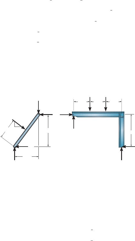
2.5 m
3 (5)
3 m
4 m
8 kN 8 kN
2 m
2 m
2 m
4 m
A
x
A
y
D
x
D
y
B
x
B
x
B
y
B
y
3
5
4
Member AB
Member BCD
Ans
Member AB
Ans
Ans
Member BCD
Ans
AnsD
y
= 14.833 kN = 14.8 kND
y
+ 1.167 - 8 - 8 = 0+
c
©F
y
= 0;
D
x
= 10.25 kN10.25 - D
x
= 0
:
+
©F
x
= 0;
A
y
= 10.167 kN = 10.2 kNA
y
- 132152
A
3
5
B
- 1.167 = 0+
c
©F
y
= 0;
A
x
= 1.75 kN-A
x
+ 31521
4
5
2- 10.25 = 0
:
+
©F
x
= 0;
B
y
= 1.167 kN = 1.17 kNB
x
= 10.25 kN
d+©M
D
= 0; 8122+ 8142- B
x
142- B
y
162= 0
d+©M
A
= 0; B
x
142- B
y
132- 315212.52= 0
