Leroy C., Rancoita P.-G. Principles Of Radiation Interaction In Matter And Detection
Подождите немного. Документ загружается.

January 9, 2009 10:21 World Scientific Book - 9.75in x 6.5in ws-bo ok975x65˙n˙2nd˙Ed
440 Principles of Radiation Interaction in Matter and Detection
nique via transition radiation and detector optimization can be found in [Dolgoshein
(1993); Egorytchev, Saveliev and Aplin (2000)].
5.5 Scintillating Fibers
Standard scintillating fibers consist of a core having a high refractive index (n
core
)
cladded with a non-scintillating material of lower refractive index (n
clad
). A scintil-
lating fiber traversed by an ionizing particle or radiation is illustrated in Fig. 5.7. The
diameter of the core material depends on the application. For particle tracking, for
which the best spatial resolution is needed, the fiber diameter is smaller than 1 mm
down to a few tens of µm. For calorimetry applications, for which the measure-
ment of energy deposition is the goal, fibers with diameter of 1 mm and above
are used. The thickness of the cladding material is a few microns, typically 2 to
5 µm. The cladding material is surrounded by a thin opaque absorber a few mm
thick, called the extra mural absorber (EMA), which captures the untrapped light.
The presence of EMA helps to prevent cross-talk between neighbouring fibers, which
θ
n
clad
n
core
Cladding
EMA
radiation
reflected photon
Scintillator/core
Fig. 5.7 Schematic description of a scintillating fiber. The core (refractive index n
core
) is cladded
with a non-scintillating material (refractive index n
clad
). The extra mural absorber (EMA) cap-
tures the untrapped light.
is essential for particle tracking.
The scintillation light produced in the fiber by the passage of a ionizing par-
ticle or radiation is trapped by internal reflections on the fiber core/cladding in-
terface. The phenomenon of internal reflection can be understood from Snell’s
law. Consider a ray of light which propagates from medium “a” of refractive in-
dex n
a
, into medium “b” of refractive index n
b
, with n
a
> n
b
. If θ
a
and θ
b
are the
angles made with the normal for the incident and refracted rays, Snell’s law says
n
a
sin θ
a
= n
b
sin θ
b
. (5.81)
From Eq. (5.81) where one has put sin θ
b
= 1, the critical angle is defined:
θ
c
= sin
−1
n
b
n
a
. (5.82)

January 9, 2009 10:21 World Scientific Book - 9.75in x 6.5in ws-bo ok975x65˙n˙2nd˙Ed
Scintillating Media and Scintillator Detectors 441
At the critical angle θ
c
, the refracted ray is tangent to the interface at the point of
incidence. Most importantly for our purpose, when the angle of incidence is larger
than the critical angle, θ
a
> θ
c
, no refracted ray appears and the incident ray
undergoes total internal reflection from the interface. The operation of scintillating
fibers is based on the principle of total internal reflection. In the case of a fiber,
Eq. (5.82) becomes:
θ
c
= sin
−1
n
clad
n
core
. (5.83)
The emitted scintillation light hitting the core/cladding interface at an angle larger
than the critical angle [Eq. (5.83)] will be reflected back into the core. The scin-
tillation light becomes trapped in the fiber and will propagate inside the fiber via
total internal reflections on the core/cladding interface until it reaches the fiber end
where it will be detected by a photosensitive device.
Typical core materials are polystyrene with n
core
= 1.59 or glasses such as GS1
(with a few % by weight of Ce
2
O
3
) with n
core
= 1.69. Cladding materials are acrylic
with n
clad
= 1.49.
For light emitted at the axis of the fiber or close to it (called meridional rays),
traveling along the fiber axis, the fraction of light trapped is:
f =
1
2
µ
1 −
n
clad
n
core
. (5.84)
In the case of isotropic light propagation inside the fiber, equal amounts are trapped
in both directions and the total fraction of trapped light is f
tot
= 2f . For n
core
=
1.59 and n
clad
= 1.49, θ
c
= 1.21, and f
tot
= 0.06. Light rays, off the fiber axis and
close to the fiber edge (called skew rays), follow spiral paths along the length of the
fiber. Adding meridional and skew rays would modify Eq. (5.84) into [Leutz (1995);
White (1988)]:
f =
1
2
"
1 −
µ
n
clad
n
core
2
#
, (5.85)
which brings f
tot
= 0.12. Skew rays have larger solid angle acceptance and undergo
more reflections at the core/cladding interface than meridional rays. Then, skew
rays are very sensible to defects in the core/cladding interface and suffer losses from
these defects which reduce their propagation length in the fiber.
The trapped light is transp orted to the fiber end via a maximum of n
r
total
internal reflections at the core/cladding interface [Leutz (1995)]:
n
r
=
l
d
cot θ
c
, (5.86)
where l and d are the fiber length and diameter, respectively. The critical angle θ
c
is given by Eq. (5.83). For a polystyrene core of diameter 0.25 mm and 1 m length
and an acrylic cladding, one finds n
r
∼ 1500.
One also defines the numerical aperture NA as [Leutz (1995)]
NA =
p
n
core
2
− n
clad
2
. (5.87)

January 9, 2009 10:21 World Scientific Book - 9.75in x 6.5in ws-bo ok975x65˙n˙2nd˙Ed
442 Principles of Radiation Interaction in Matter and Detection
Taking a fiber with a polystyrene core and an acrylic cladding, the numerical aper-
ture is N A = 0.55.
For tracking purpose, one wishes to select fibers with diameter as small as possi-
ble to achieve good spatial resolution. From Eq. (5.86), one can see that the decrease
of the fiber diameter increases the number of reflections and, therefore, additional
light losses due to defects in the core/cladding interface are expected. The light in-
tensity I after n
r
reflections is related to the initial light intensity I
0
through [Leutz
(1995)]:
I = I
0
q
n
r
, (5.88)
where q ≤ 1 is the reflection coefficient whose value reflects light losses at the
core/cladding interface. The combination of Eqs. (5.86, 5.88) gives:
ln
I
I
0
= −(1 − q)
l
d
cot θ
c
, (5.89)
where ln q has been replaced by (q − 1), since q is very close to unity. The expe-
rimental value [Leutz (1995)] of (1 − q) is typically (5 − 6) × 10
−5
, depending on
wavelength. The reflection length, Λ
R
, is the fiber length after which the initial light
intensity is reduced to 1/e of its value as the result of reflection losses. It is given
by [Leutz (1995)]:
Λ
R
=
1.5
1 − q
n
core
NA
d. (5.90)
The total attenuation length, Λ, is the sum [Leutz (1995)] (see discussion in this
reference):
Λ
−1
= Λ
A
−1
+ Λ
R
−1
+ Λ
Sc
−1
, (5.91)
where Λ
A
is defined as the value of the light path length D (in meters) at which
the light yield drops to 1/e of its initial value at zero D. The attenuation, Λ
Sc
,
quantifies Rayleigh scattering on small density fluctuations in the core material
that can deflect a light ray which is no longer totally internally reflected.
5.6 Detection of the Scintillation Light
The ionization energy deposited by a particle traversing a scintillator material is
converted into photons. If one considers a plastic scintillator such as NE102A (see
Table 5.1), a scintillation photon is produced for about 3 keV of deposited energy,
which corresponds to a yield of about 500 photons per centimeter of scintillator
material. This scintillation light is of low intensity and has to be optically coupled
to a photomultiplier for amplification in order to provide an electrical signal. A
schematic view of a photomultiplier is given in Fig. 5.8. The scintillation light has
to be transported to the photocathode of the photomultiplier where the impinging
January 9, 2009 10:21 World Scientific Book - 9.75in x 6.5in ws-bo ok975x65˙n˙2nd˙Ed
Scintillating Media and Scintillator Detectors 443
photons will be converted into photoelectrons via the photoelectric effect (Einstein
equation):
E = hν − φ, (5.92)
where E is the kinetic energy of the emitted electron, ν is the frequency of incident
scintillation light and φ is the work function. The surface of the photocathode is
coated with a photosensitive material that has a low work function to favor electron
emission. The probability of this photon to electron conversion is the quantum
efficiency QE of the photocathode, i.e., the probability of liberating an electron per
photon striking the photocathode:
QE(λ) =
number of photoelectrons emitted
number of photons incident on the photocathode
. (5.93)
Photoelectrons
Dynode
Anode
Shield
Focusing grid
Incident radiation
Photocathode
Fig. 5.8 Schematic view of a photomultiplier.
The quantum efficiency depends on the type of photocathode material. The type
of photocathode is chosen to have an overlap between its peak spectral response
and the characteristic wavelength at maximum emission of the incoming light. The
quantum efficiency is typically 20–25%.
A plastic light guide couples the scintillator to the photomultiplier. A “fish tail”
shape for the light guide is standard (Fig. 5.9), but other shap es are also used
January 9, 2009 10:21 World Scientific Book - 9.75in x 6.5in ws-bo ok975x65˙n˙2nd˙Ed
444 Principles of Radiation Interaction in Matter and Detection
depending on the application. It allows the coupling of photocathode, which are
of small area, to a scintillator with a large cross section. The light emitted in the
Scintillator plate
Photomultiplier
Photomultiplier
base
Light guide (fish tail)
Fig. 5.9 Schematic view of a scintillator coupled to a photomultiplier via a fish tail light guide.
scintillator is transported to the photocatho de through the scintillator and light
guide via total internal reflections. When the emitted light strikes the scintillator
surface, total internal reflection occurs when the incident angle is larger than the
critical angle [Eq. (5.83)]. In the present situation, Eq. (5.83) becomes
:
θ
c
= sin
−1
n
med
n
. (5.94)
The surrounding medium is often air, n
med
= n
air
= 1, and Eq. (5.94) becomes:
θ
c
= sin
−1
1
n
. (5.95)
For the example of NE102A above, n = 1.58 and therefore Eq. (5.95) gives θ
c
=
39.2
◦
. The fraction f of light emitted and transported via total internal reflection
in one direction is (e.g., see Equation 7.4 of [Fernow (1986)]):
f =
1
4π
Z
2π
0
Z
θ
c
0
sin θ dθ dφ
=
1
2
(1 − cos θ
c
)
=
1
2
Ã
1 −
√
n
2
− 1
n
!
w 0.11. (5.96)
The scintillator and light guide are wrapped with an aluminium foil to prevent the
leak, from plastic, of light escaping total internal reflection. The scintillator, light
guide and photomultiplier are also wrapped with a layer of black tape to prevent
outside light from leaking inside the detector.
In this case, the cladding is replaced by the surrounding medium of refractive index n
med
and
the core by scintillator of refractive index n.

January 9, 2009 10:21 World Scientific Book - 9.75in x 6.5in ws-bo ok975x65˙n˙2nd˙Ed
Scintillating Media and Scintillator Detectors 445
Geometrical constraints often forces the bending of the light guide (which could
be also a bundle of fibers) to achieve the coupling to the photomultiplier. However,
there exists a limit for maximum bending beyond which important light losses
occur. The maximum bending is calculated from the condition (Liouville’s law):
n
2
− 1 ≥
µ
d
2r
+ 1
2
, (5.97)
where d is the light guide diameter, r is the bending radius and n is the refractive
index relative to air. If the bending radius satisfies condition Eq. (5.97), the light
will be transported along the light guide via total internal reflections.
The intensity of light transported in the scintillator and light guide is attenuated
by atomic absorption and scattering from imperfections of the reflecting surface
(which should be negligible if the surface has been cleanly polished). The reduction
of light intensity, I, is a function of distance, l, and light wavelength, λ, can be
expressed by:
I(l, λ) = I(0, λ) exp
µ
−
l
I
ph
(λ)
, (5.98)
where I(l, λ) is the light intensity at distance l and wavelength λ, I(0, λ) is the
initial light intensity and I
ph
(λ) is the photon attenuation length at wavelength
λ. As seen in Sect. 5.3, the introduction of a wavelength shifter in the scintillator
increases the attenuation length. Taking into account Eqs. (5.93, 5.96, 5.98), the
numb er of photoelectrons produced by the photocathode can be expressed by:
n
pe
= n
ph
Z
I(L, λ) QE(λ) f(λ) dλ, (5.99)
where f , in Eq. (5.96), now depends on λ, and n
ph
is the number of photons
produced in the scintillator of length L. Let us consider the example of a NE102A
scintillator counter of 1 cm thickness. Its light output is about 25% of NaI(Tl) (see
Table 5.1), i.e., 10
4
γ/MeV or 1 γ/100 eV. A minimum ionizing particle traversing
the scintillator thickness loses about 2 MeV/cm. Therefore, about 2×10
4
γ should be
emitted in 1 cm of scintillator. NE102A has an attenuation length of 250 cm which
gives an intensity loss of 0.4% in 1 cm according to Eq. (5.98). The fraction of
light trapped in scintillator within the critical angle is directly given by Eq. (5.96),
since the refractive index of NE102A is 1.58. Assuming a quantum efficiency of
20% for the photocathode and an optical collection efficiency of about 50% (due
to imperfections of the reflecting surface and imperfect coupling of the light guide
to the photocathode), one finds the number of photoelectrons, n
pe
, coming off the
photocatho de:
n
pe
≈ 220. (5.100)
The number of photoelectrons produced at the photocathode follows a Poisson
distribution P (n
pe
) and the probability of production of n
pe
photoelectrons for a
mean number ¯n
pe
is (Appendix B.1):
P (n
pe
) =
¯n
n
pe
pe
e
−¯n
pe
n
pe
!
. (5.101)

January 9, 2009 10:21 World Scientific Book - 9.75in x 6.5in ws-bo ok975x65˙n˙2nd˙Ed
446 Principles of Radiation Interaction in Matter and Detection
The detector efficiency, ², is the detection probability which is the complement of
non-detection probability. Therefore, one has:
1 − ² = e
−¯n
pe
, (5.102)
where e
−¯n
pe
is the inefficiency or the probability of detecting no photoelectron. In
this example, Eq. (5.100) gives e
−¯n
pe
' 0 and the efficiency, ², is ' 100%.
The photomultiplier is powered by a high voltage power supply. The photocath-
ode, made of alkali metals, is the most negative electrode and put at a large negative
voltage, e.g., −1400 V up to −2200 V. The anode is at 0 V.
A set of metallic electrodes, called dynodes, forms the electron multiplier sec-
tion. The dynodes, set at progressively higher voltage, e.g., steps of (100–120) V, are
located between the photocathode and the anode (see Fig. 5.8). A dynode re-emits
electrons when struck by an electron. This emission of secondary electrons by a dy-
node, via the photoelectric effect [Eq. (5.92)], is similar to photoelectron emission
by the photocathode. However, there is a major difference: incoming electrons are
responsible for secondary electron emission in the case of the dynode, while incident
scintillation photon are responsible for this emission for the photocathode. Like the
photocatho de, dynodes are made of low work function material to maximize elec-
tron emission by photoelectric effect. Voltage to each dynode is delivered through
a resistive potential divider consisting of a chain of resistors in series contained in
the photomultiplier base (Fig. 5.9). The electrons ejected from the photocathode
are accelerated towards the first dynode due to the difference of potential of (100–
120) V between the photocathode and the first dynode, from which they knock out
several electrons. These secondary electrons are accelerated, through the potential
gradient between the first and second dynodes, towards the second dynode, where
each of them ejects more electrons, and so on. The inter-dynode voltage allows the
multiplication of secondary electrons via photoelectric effect from dynode to dy-
node, until they reach the anode where the charge is collected. The multiplication
factor (called the gain), M , between the first stage of the n-dynode chain and the
anode is
M = δ
1
δ
2
δ
3
. . . δ
n
, (5.103)
where δ
i
is the multiplication factor at the dynode i of the chain. From Eq. (5.103),
a standard multiplication factor of 10
7
with a chain of 12 dynodes can be achieved,
if each electron produces about 4 secondary electrons when it strikes a dynode. A
chain of 10 dynodes would reduce M to 10
6
. The charge collected at the anode for
M = 10
7
is then
Q = e 10
7
= 1.6 × 10
−19
C × 10
7
= 1.6 × 10
−12
C = 1.6 pC. (5.104)
Since the charge is collected typically within 5 ns, the current at the anode is:
i =
dQ
dt
=
1.6 × 10
−12
C
5 × 10
−9
= 0.32 mA. (5.105)
January 9, 2009 10:21 World Scientific Book - 9.75in x 6.5in ws-bo ok975x65˙n˙2nd˙Ed
Scintillating Media and Scintillator Detectors 447
Usually, the signal drives a 50 Ω load, i.e., the photomultiplier is terminated with
a 50 Ω resistance. Then, a pulse of
δV = 0.32 mA × 50 Ω = 16 mV (5.106)
is produced. Photomultipliers are also characterized by a rise-time (about 2 ns,
typically). The rise-time is usually defined as the time required for the output signal
to increase from 10% to 90% of the maximal value. The time elapsed between
the illumination of the photocathode and the signal at the anode is the transit
time (about 30 ns, typically), which can be understood as the time needed for the
electron to travel the length of the photomultiplier. Information about the rise-time
and transit time are given by technical specifications released by the manufacturer
of the photomultiplier. The output pulse at the anode is subsequently analyzed by
an electronics system. A example of such a system is shown in Fig. 5.10.
PHAAMP
S, T, etc
PM
PA
HV
Fig. 5.10 Schematic description of an analyzing electronics system consisting of a preamplifier
(PA), a high voltage power source (HV), an amplifier (AMP), a pulse height analyzer (PHA),
followed by a spectrometer analyzer (S), a timing unit (T), etc. . .
The size of the pulse at the anode is proportional to the energy absorbed from
the incident radiation by the scintillating material. This is the consequence of the
proportionality between the amount of light that reaches the photocathode surface
and the amount of photoelectrons ejected. Therefore, the scintillation detector can
be used to distinguish between different types of particles or incoming particles of
different energy by the shape of the emitted light pulse. The pulse produced by a
scintillator detector is controlled by the dominant decay time of the scintillator and
the electron transit time through the PM chain. The number of photons emitted
after the passage of the ionization radiation follows the exp onential law described by
Eq. (5.8) with decay constants for various scintillators ranging from a few nanosec-
onds to a few microseconds (Tables 5.2 and 5.3). The electron transit time is a
Gaussian function of time with a standard deviation of about 1 ns. When the scin-
tillator decay constant is 10 ns or larger, the effect of the spread in the electron
transit time is negligible.
January 9, 2009 10:21 World Scientific Book - 9.75in x 6.5in ws-bo ok975x65˙n˙2nd˙Ed
448 Principles of Radiation Interaction in Matter and Detection
5.7 Applications in Calorimetry
A variety of scintillating and
˘
Cerenkov materials can be used as the active medium
of homogeneous calorimeters (see Sect. 9.5) or active samplers of sampling calorime-
ters. The choice of a particular active medium is made to achieve the b est possible
energy and position resolutions over an energy range as large as possible (from MeV
up to TeV energies), taking into account practical and physical requirements. The
energy resolution is determined by the fluctuations in the number of photons or ion
pairs produced by the cascade. The light yield, i.e, the number of photons produced
per MeV of energy deposition, should be large enough to minimize the contribution
of the statistical fluctuations to the energy resolution.
A comprehensive treatment of calorimeter performance can be found in the
chapter Principles of Particle Energy Determination.
5.8 Application in Time-of-Flight (ToF) Technique
The excellent timing capabilities of scintillator counters make them applicable in
time-of-flight (ToF) techniques [Atwood (1981)]. Measurements of particles ToF,
combined with the knowledge of their momentum, give information on their
mass. Therefore, ToF measurement may allow discrimination between particle of
same momentum but different masses.
The speed of a particle of mass m, momentum p, traveling a distance L in a
time t is given by
v =
L
t
, (5.107)
then,
β =
v
c
=
L
ct
. (5.108)
Using Eq. (5.32) with γ = 1/
p
1 − β
2
, one finds:
m =
p
βγc
=
p
c
r
c
2
t
2
L
2
− 1. (5.109)
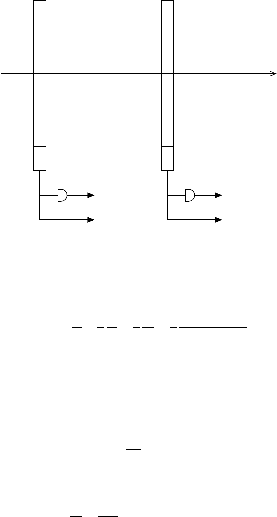
A ToF measurement system consists of two scintillator plastic counters as shown
in Fig. 5.11. Plastic scintillators are chosen for their fast response. One of the coun-
ters serves as start counter, the other as stop counter. The time information is given
by a time to digital-converter (TDC) while charge measurement is obtained from
analog to digital converter (ADC).
If two scintillator counters are separated by a distance L, two particles “1” and
“2” of momentum p, with masses m
1
and m
2
, velocities v
1
and v
2
and energies E
1
and E
2
will traverse this distance with times of flight
t
1
=
L
v
1
=
L
c
1
β
1
=
L
c
E
1
pc
=
L
c
p
m
1
2
c
4
+ p
2
c
2
pc
(5.110)
January 9, 2009 10:21 World Scientific Book - 9.75in x 6.5in ws-bo ok975x65˙n˙2nd˙Ed
Scintillating Media and Scintillator Detectors 449
TDC(t )
ADC(A )
PM
DISC
ADC(A )
DISC
PM
TDC(t )
particle
1
1 2
2
Stop
counter
Start
counter
Fig. 5.11 Schematic description of a T oF measurement system. The start and stop counters, 1
and 2, respectively, are read each by a photomultiplier (PM). The chain of time measurement
for each counter consists of a discriminator (DISC) and a TDC(t
i
), while charge measurement is
obtained from an ADC(A
i
).
and
t
2
=
L
v
2
=
L
c
1
β
2
=
L
c
E
2
pc
=
L
c
p
m
2
2
c
4
+ p
2
c
2
pc
. (5.111)
There will be a ToF difference between these two particles of
∆t = t
2
− t
1
=
L
pc
2
³
p
m
2
2
c
4
+ p
2
c
2
−
p
m
1
2
c
4
+ p
2
c
2
´
. (5.112)
For relativistic particles, pc >> mc
2
, Eq. (5.112) may be approximated by:
∆t =
L
pc
2
pc
·µ
1 +
m
2
2
c
2
2p
2
−
µ
1 +
m
1
2
c
2
2p
2
¶¸
, (5.113)
or
∆t =
Lc
2p
2
(m
2
2
− m
1
2
). (5.114)
In practice, the distance L is one or several meters and times of reference such as
times of resolution are in picoseconds (ps). Therefore, it is standard to express the
ration ∆t/L in ps/m units:
∆t
L
=
1667
p
2
c
2
(m
2
2
c
4
− m
1
2
c
4
) [ps/m]. (5.115)