Lewis R.I. Turbomachinery Performance Analysis
Подождите немного. Документ загружается.

124
Simplified meridional flow analysis for axial turbomachines
to r t with Ar = (r t -rh)/m. The constant of integration follows from the continuity
equation (5.20) which leads to
2 Is t
K1 = Cx + (~_ r2 ) rL(r, Cx2) dr
2Ar
m
Cx + (r 2 _ r2 ) ~ ri L(ri, Cx2)
i=1
(5.47)
However, we note that
Cx2
also appears in the expression for
L(r,
Cx2), Eqn (5.46),
and an iterative approach is required as shown in Fig. 5.6.
The computer program RE-ANAL, the source code of which is given on the
accompanying PC disc, executes this computational sequence for which sample output
is given in Table 5.5.
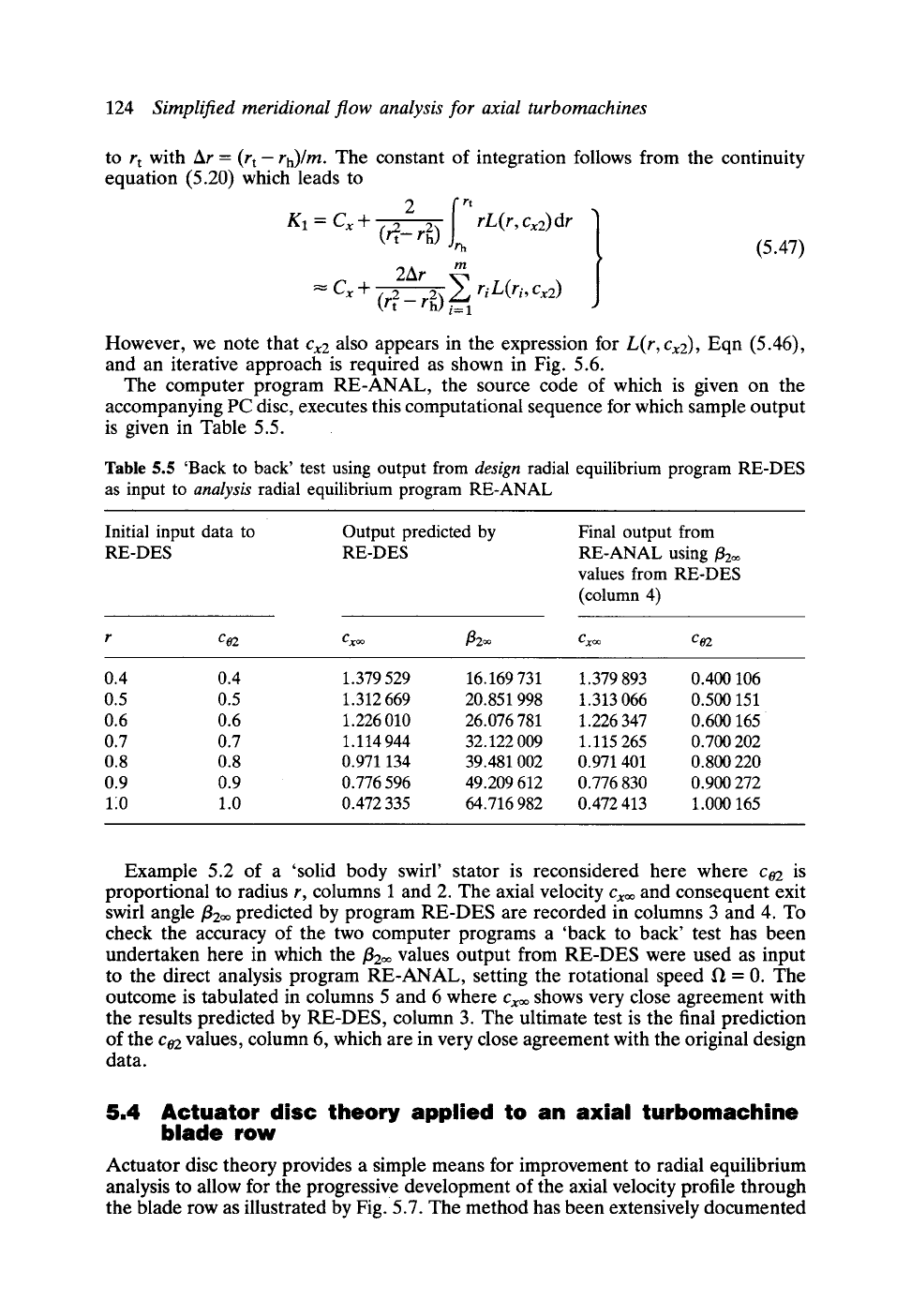
Table
5.5 'Back to back' test using output from
design
radial equilibrium program RE-DES
as input to
analysis
radial equilibrium program RE-ANAL
Initial input data to
RE-DES
Output predicted by
RE-DES
Final output from
RE-ANAL using
f12oo
values from RE-DES
(column 4)
r
ca2
Cxoo [3200 Cx~ C02
0.4 0.4 1.379 529 16.169 731 1.379 893 0.400 106
0.5 0.5 1.312 669 20.851 998 1.313 066 0.500 151
0.6 0.6 1.226 010 26.076 781 1.226 347 0.600 165
0.7 0.7 1.114 944 32.122 009 1.115 265 0.700 202
0.8 0.8 0.971 134 39.481 002 0.971 401 0.800 220
0.9 0.9 0.776 596 49.209 612 0.776 830 0.900 272
120 1.0 0.472 335 64.716 982 0.472 413 1.000 165
Example 5.2 of a 'solid body swirl' stator is reconsidered here where co2 is
proportional to radius r, columns 1 and 2. The axial velocity
Cxoo
and consequent exit
swirl angle/3200 predicted by program RE-DES are recorded in columns 3 and 4. To
check the accuracy of the two computer programs a 'back to back' test has been
undertaken here in which the/3200 values output from RE-DES were used as input
to the direct analysis program RE-ANAL, setting the rotational speed f~ = 0. The
outcome is tabulated in columns 5 and 6 where
Cxoo
shows very close agreement with
the results predicted by RE-DES, column 3. The ultimate test is the final prediction
of the ca2 values, column 6, which are in very close agreement with the original design
data.
5.4
Actuator disc theory applied to an axial turbomachine
blade row
Actuator disc theory provides a simple means for improvement to radial equilibrium
analysis to allow for the progressive development of the axial velocity profile through
the blade row as illustrated by Fig. 5.7. The method has been extensively documented
5.4 Actuator disc theory applied to an axial turbomachine blade row
125
D
Cx
l r t
lrh
/ /
c x Cxo,
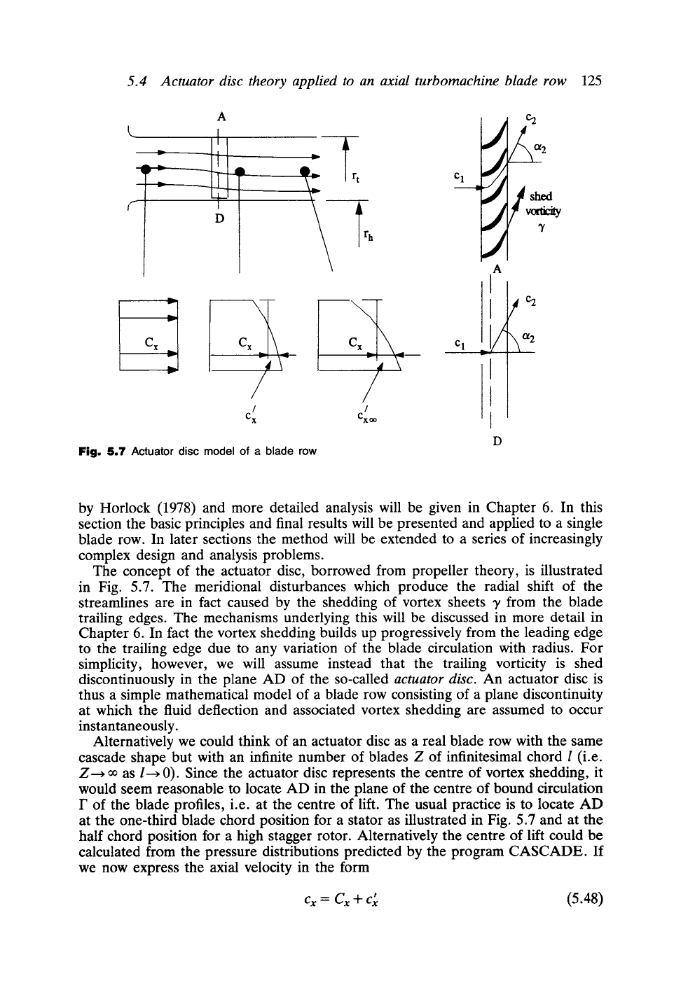
Fig. 5.7
Actuator disc model of a blade row
o~ 2
~2__
shed
A
Cl ~~ ~2
w..--,,
I
I
I
by Horlock (1978) and more detailed analysis will be given in Chapter 6. In this
section the basic principles and final results will be presented and applied to a single
blade row. In later sections the method will be extended to a series of increasingly
complex design and analysis problems.
The concept of the actuator disc, borrowed from propeller theory, is illustrated
in Fig. 5.7. The meridional disturbances which produce the radial shift of the
streamlines are in fact caused by the shedding of vortex sheets y from the blade
trailing edges. The mechanisms underlying this will be discussed in more detail in
Chapter 6. In fact the vortex shedding builds up progressively from the leading edge
to the trailing edge due to any variation of the blade circulation with radius. For
simplicity, however, we will assume instead that the trailing vorticity is shed
discontinuously in the plane AD of the so-called
actuator disc.
An actuator disc is
thus a simple mathematical model of a blade row consisting of a plane discontinuity
at which the fluid deflection and associated vortex shedding are assumed to occur
instantaneously.
Alternatively we could think of an actuator disc as a real blade row with the same
cascade shape but with an infinite number of blades Z of infinitesimal chord l (i.e.
Z~ ~ as l---~ 0). Since the actuator disc represents the centre of vortex shedding, it
would seem reasonable to locate AD in the plane of the centre of bound circulation
F of the blade profiles, i.e. at the centre of lift. The usual practice is to locate AD
at the one-third blade chord position for a stator as illustrated in Fig. 5.7 and at the
half chord position for a high stagger rotor. Alternatively the centre of lift could be
calculated from the pressure distributions predicted by the program CASCADE. If
we now express the axial velocity in the form
Cx = Cx + Cx
(5..48)
126
Simplified meridional flow analysis for axial turbomachines
I
Cx
e(x) =
-;-
Cx=,
1
0.9
0.8
0.7
0.6
0.5
0.4
0.3
0.2
0.1
0
-2
-1'.5 -'1 "-0'.5
0
ols i , ;is
2
rt-r h
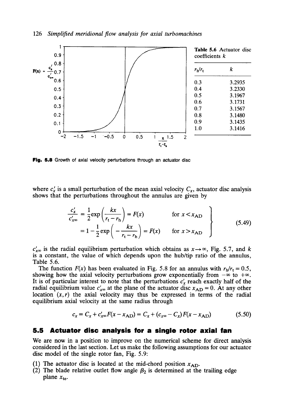
Table 5.6 Actuator disc
coefficients k
rh/r t k
0.3 3.2935
0.4 3.2330
0.5 3.1967
0.6 3.1731
0.7 3.1567
0.8 3.1480
0.9 3.1435
1.0 3.1416
Fig. 5.8 Growth of axial velocity perturbations through an actuator disc
where Cx is a small perturbation of the mean axial velocity
Cx,
actuator disc analysis
shows that the perturbations throughout the annulus are given by
c;
t
CX=
1
=
~exp
=
F(x)
for x <XAD
rt- rh
1
= 1 - ~ exp =
F(x)
for x > XAD
r t - r h
(5.49)
Cx= is the radial equilibrium perturbation which obtains as x--~ oo, Fig. 5.7, and k
is a constant, the value of which depends upon the hub/tip ratio of the annulus,
Table 5.6.
The function
F(x)
has been evaluated in Fig. 5.8 for an annulus with
rh/rt
= 0.5,
showing how the axial velocity perturbations grow exponentially from -oo to +~.
It is of particular interest to note that the perturbations Cx reach exactly half of the
radial equilibrium value Cx= at the plane of the actuator disc XAD
=
0. At any other
location
(x,r)
the axial velocity may thus be expressed in terms of the radial
equilibrium axial velocity at the same radius through
C x = C x Jr CxooF(x-
XAD ) =
C x -4- (Cxoo- Cx)F(x-
XAD )
(5.5o)
5.5 Actuator disc analysis for a single rotor axial fan
We are now in a position to improve on the numerical scheme for direct analysis
considered in the last section. Let us make the following assumptions for our actuator
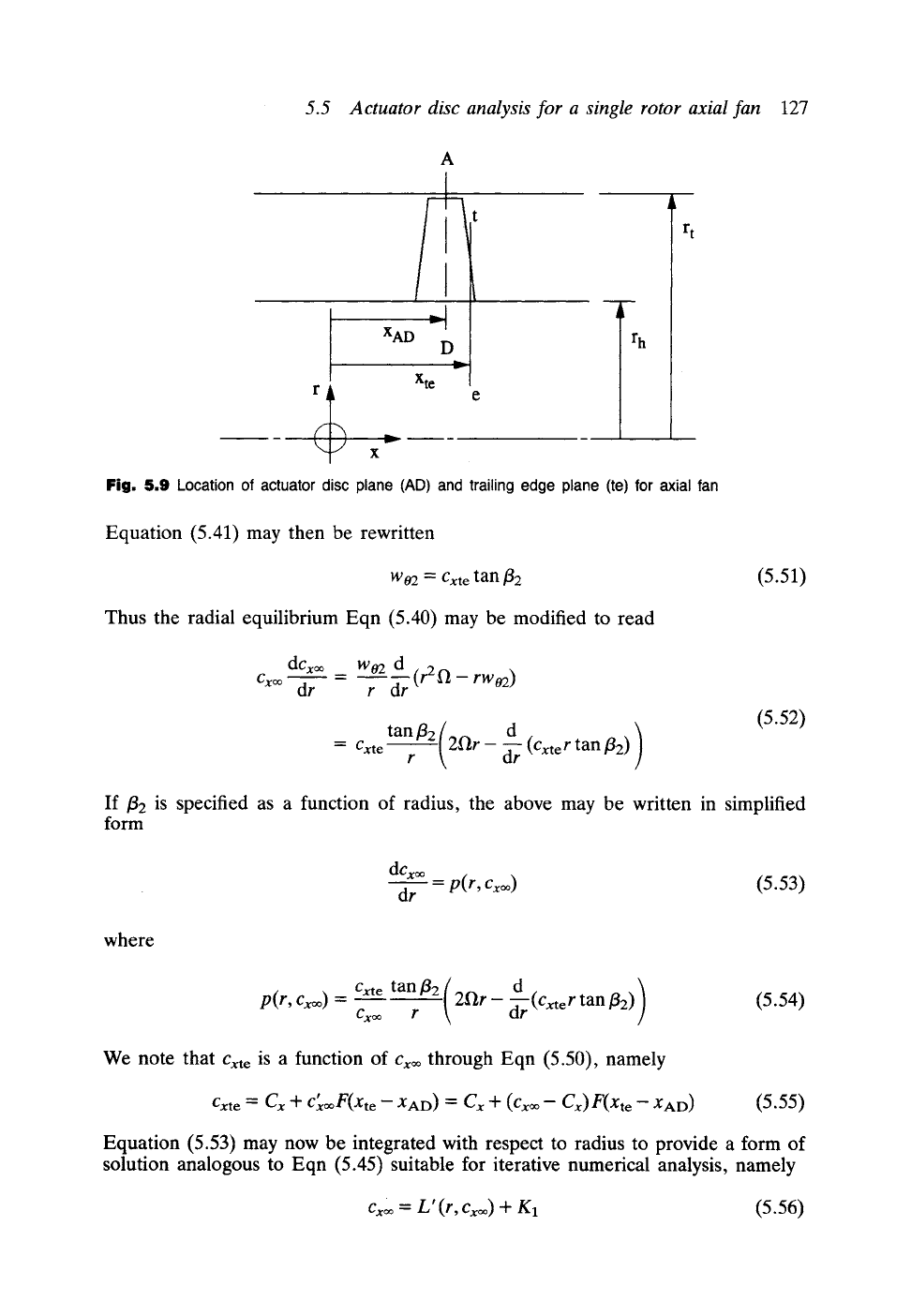
disc model of the single rotor fan, Fig. 5.9"
(1) The actuator disc is located at the mid-chord position XAD.
(2) The blade relative outlet flow angle
~2
is determined at the trailing edge
plane xte.
5.5 Actuator disc analysis for a single rotor axial fan
127
A
XAD
D
u,..--
r h
Xte
'-V x
Fig, 5,9 Location of actuator disc plane (AD)
and trailing edge plane (te) for axial fan
Equation (5.41) may then be rewritten
W02 : Cxt e
tan f12
(5.51)
Thus the radial equilibrium Eqn (5.40) may be modified to read
dcx~ Wo2 d
= ~--(r2fl-rwo2)
Cx= dr r dr
tan/32 (2ftr -d )
-" Cxte
r -~r
(Cxter
tan f12)
(5.52)
If/32 is specified as a function of radius, the above may be written in simplified
form
dcx~
dr = p(r, Cx~ )
(5.53)
where
p(r, Cx=)
= Cxte
tan
f12
( 2fir -- d
Cx~
r
d'r'r (Cxte
r tan/32) ) (5.54)
We note that
Cxt e
is a function of Cx= through Eqn (5.50), namely
Cxt e = C x + cx~F(xte -
XAD ) =
C x Jr (Cx~ - Cx)
F(xte - XAD )
(5.55)
Equation (5.53) may now be integrated with respect to radius to provide a form of
solution analogous to Eqn (5.45) suitable for iterative numerical analysis, namely
Cx= = L' (r, Cx=) +
gl
(5.56)
128
Simplified meridional flow analysis for axial turbomachines
where at radius
rj
i
rj
L'(rj, Cx~) = p(r, Cx~)dr
h
J
~.Ar
Ep i
i=1
(5.57)
The previous iterative scheme, Fig. 5.6, may then be used with slight modification
to achieve a numerical solution for
Cx~
bysuccessive approximations and hence for
Cx
at any other axial location in the annulus making use of Eqn (5.50).
Two computer programs are given on the accompanying PC disc which undertake
actuator disc analyses for single blade rows. Program AD-ANAL solves the 'analysis'
problem, predicting the fl0w through a blade row of prescribed efflux angle /32.
Program AD-DES solves the opposite 'design' problem, predicting the efflux angle
/32 required in order to generate a prescribed swirl velocity distribution c02. Studies
will be undertaken in the next two sections to illustrate these design and analysis
problems.
5.5.1 Actuator disc design of a solid body swirl stator
To bring out the deficiencies of radial equilibrium analysis, the r-c02 data given in
Table 5.5 have been used as input into the actuator disc design program AD-DES
and the results are given in Table 5.7. Although AD-DES has been written to deal
with fan rotor design, a stator may also be designed by simply specifying zero speed
of rotation, fl = 0.
Two solutions are illustrated here as follows:
(1) The
radial equilibrium solution,
obtained by placing the actuator disc
artificially a very long way upstream of the blade row (XAD =--1000 was
used here).
(2) The
actuator disc solution
with the following locations:
Leading edge located at XLE = 0.0
Actuator disc located at XAD = 0.1
Trailing edge located at XTE = 0.2
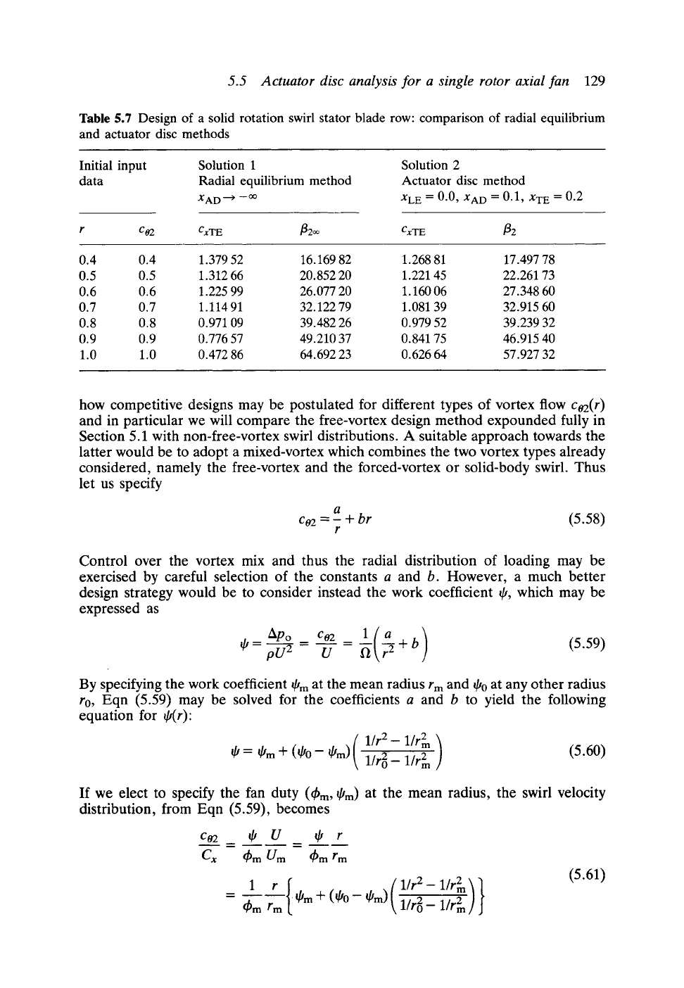
Our design aim here is to predict the blade efflux angle/32 distribution which would
generate the specified swirl velocity c02 given in column 2 with a mean axial velocity
Cx
= 1.0. Two observations may be made:
(a) Solution (1) is in close agreement with the previous radial equilibrium
solution shown in Table 5.5.
(b) The true blade trailing edge efflux angles/32 according to actuator disc
analysis, solution (2), differ significantly from the/32~ values a long way
downstream delivered by radial equilibrium analysis.
5.5.2 Actuator disc design and analysis of a single stage rotor axial fan
For our second study let us reconsider the axial fan illustrated in Fig. 5.5 which
comprises a single rotor only. Our aim will be to generate velocity triangle design
data from an initial specification of c02 versus radius, including also meridional flow
analysis by actuator disc theory. Program AD-DES will then be used to demonstrate
5.5 Actuator disc analysis for a single rotor axial fan
129
Table 5.7 Design of a solid rotation swirl stator blade row: comparison of radial equilibrium
and actuator disc methods
Initial input
data
Solution 1
Radial equilibrium method
XAD ~ --
Solution
2
Actuator disc method
XLE = 0.0, XAD = 0.1, XTE = 0.2
r c02 CxTE fl2oo CxTE [32
0.4 0.4 1.379 52 16.169 82 1.268 81 17.497 78
0.5 0.5 1.312 66 20.852 20 1.221 45 22.261 73
0.6 0.6 1.225 99 26.077 20 1.160 06 27.348 60
0.7 0.7 1.114 91 32.122 79 1.081 39 32.915 60
0.8 0.8 0.971 09 39.482 26 0.979 52 39.239 32
0.9 0.9 0.776 57 49.210 37 0.841 75 46.915 40
1.0 1.0 0.472 86 64.692 23 0.626 64 57.927 32
how competitive designs may be postulated for different types of vortex flow
co2(r)
and in particular we will compare the free-vortex design method expounded fully in
Section 5.1 with non-free-vortex swirl distributions. A suitable approach towards the
latter would be to adopt a mixed-vortex which combines the two vortex types already
considered, namely the free-vortex and the forced-vortex or solid-body swirl. Thus
let us specify
a
co2 = - + br
(5.58)
r
Control over the vortex mix and thus the radial distribution of loading may be
exercised by careful selection of the constants a and b. However, a much better
design strategy would be to consider instead the work coefficient ~, which may be
expressed as
l(a )
=~= U = ~ ~ +b (5.59)
By specifying the work coefficient qJm at the mean radius r m and ~o at any other radius
r0, Eqn (5.59) may be solved for the coefficients a and b to yield the following
equation for ~(r):
( l/r2-1/r2 )
= ~m q- (~0- ~m)
1/r E _ 1/r 2
(5.60)
If we elect to specify the fan duty
(t~m ,
~m) at the mean radius, the swirl velocity
distribution, from Eqn (5.59), becomes
c02 ~, U ~ r
m
C x
-t~mU m ~mrm
1 r{
t~m rm I/tm
+ (qJo- qhn)(
1/r2- 1/r2
llrE-1/r2 ) }
(5.61)
130
Simplified meridional flow analysis for axial turbomachines
where
Cx
is the mean axial velocity. Close inspection confirms that this equation
conforms with the original mixture of free-vortex and forced-vortex, Eqn (5.58), but
instead makes use of much more helpful initial design data. Thus Co2 is now
determined in terms of the design duty (~bm, ~'m) at rm, and for a prescribed work
coefficient q'0 at any chosen reference radius r0.
At this point attention might usefully be directed to the following two special vortex
cases.
(1)
Free-vortex swirl (b
= 0). A free-vortex swirl distribution is obtained if we
specify that
Co20 rm
C 02m ro
and hence t/,0 must be given the value
= (5.62)
As shown in Section 4.7 for zero inlet swirl, the reaction of such a rotor-only
fan becomes
~0
R=I
2
for the free-vortex fan
[4.41]
Thus the radial variation of both work coefficient t/, and reaction will be very
considerable for a free-vortex fan, as was shown in Table 5.1.
(2)
Forced-vortex or constant reaction fan rotor.
A pure solid-body swirl or
forced-vortex will be delivered by Eqn (5.61) by specifying q'o = q'm at the
reference radius r0. In this case Eqns (5.60) and (5.61) reduce to
~' = ~'m (5.60a)
c02 qJm r
= (5.61a)
Cx q~m
rm
Thus a fan rotor designed to generate a forced-vortex exit swirl c02 will have
the same work coefficient at all radii. From Eqn (4.41) we see that the
reaction R will also be constant at all radii and equal to R = 1- ~m/2.
Two fan designs have been completed on this basis using the program AD-DES
for the common data specification given at the head of Table 5.8. For these designs
a hub/tip ratio h = 0.4 was chosen and rm was set at the r.m.s, radius. At r m the
selected duty coefficients
were t~m =
0.5 and
~t m =
0.3. The hub section was chosen
for the representative radius r0 at which the work coefficient was set at q'0 = 1.0875
for the free-vortex fan (see Eqn (5.62)) and at 0.5 for the mixed-vortex fan.
5.5 Actuator disc analysis for a single rotor axial fan
131
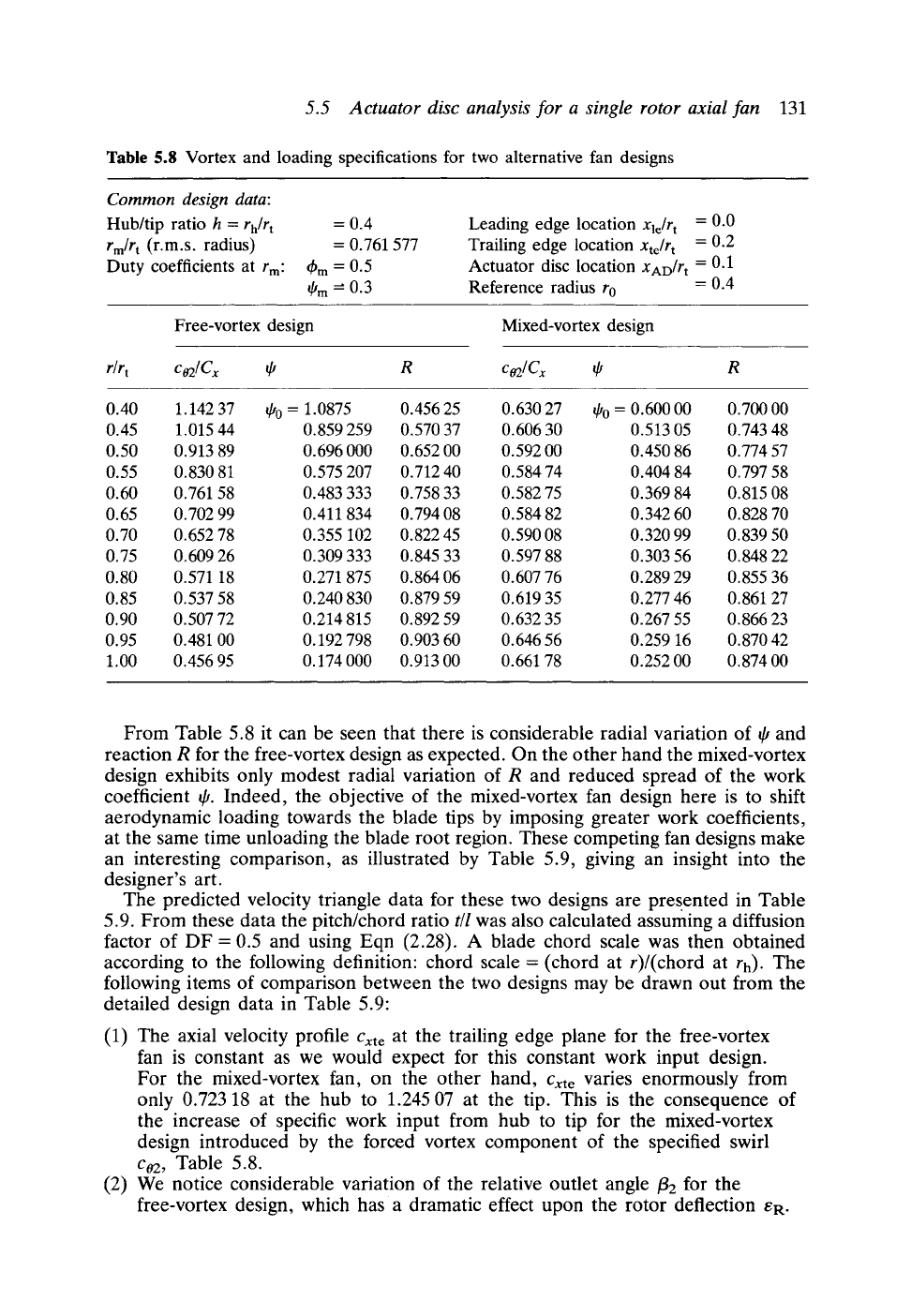
Table 5.8 Vortex and loading specifications for two alternative fan designs
Common design data:
Hub/tip ratio h =
rh/rt
rm/r t
(r.m.s. radius)
Duty coefficients at rm:
=0.4
= 0.761 577
t~m "- 0.5
q,m --- 0.3
Leading edge location
Xle/r t --0.0
Trailing edge location
Xte/r t
--0.2
Actuator disc location XAD/rt = 0.1
Reference radius r0 = 0.4
Free-vortex design
Mixed-vortex design
r/r t Co2/C x ~b R Co2/Cx ~b R
0.40 1.142 37 qJ0 = 1.0875 0.456 25 0.630 27 qJ0 = 0.600 00 0.700 00
0.45 1.015 44 0.859 259 0.570 37 0.606 30 0.513 05 0.743 48
0.50 0.913 89 0.696 000 0.652 00 0.592 00 0.450 86 0.774 57
0.55 0.830 81 0.575 207 0.712 40 0.584 74 0.404 84 0.797 58
0.60 0.761 58 0.483 333 0.758 33 0.582 75 0.369 84 0.815 08
0.65 0.702 99 0.411 834 0.794 08 0.584 82 0.342 60 0.828 70
0.70 0.652 78 0.355 102 0.822 45 0.590 08 0.320 99 0.839 50
0.75 0.609 26 0.309 333 0.845 33 0.597 88 0.303 56 0.848 22
0.80 0.571 18 0.271 875 0.864 06 0.607 76 0.289 29 0.855 36
0.85 0.537 58 0.240 830 0.879 59 0.619 35 0.277 46 0.861 27
0.90 0.507 72 0.214 815 0.892 59 0.632 35 0.267 55 0.866 23
0.95 0.481 00 0.192 798 0.903 60 0.646 56 0.259 16 0.870 42
1.00 0.456 95 0.174 000 0.913 00 0.661 78 0.252 00 0.874 00
From Table 5.8 it can be seen that there is considerable radial variation of q, and
reaction R for the free-vortex design as expected. On the other hand the mixed-vortex
design exhibits only modest radial variation of R and reduced spread of the work
coefficient qJ. Indeed, the objective of the mixed-vortex fan design here is to shift
aerodynamic loading towards the blade tips by imposing greater work coefficients,
at the same time unloading the blade root region. These competing fan designs make
an interesting comparison, as illustrated by Table 5.9, giving an insight into the
designer's art.
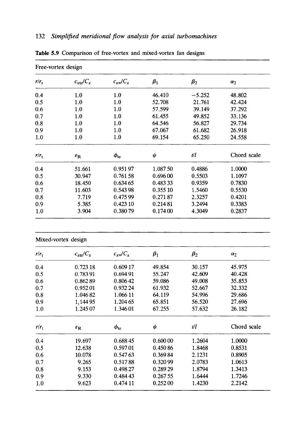
The predicted velocity triangle data for these two designs are presented in Table
5.9. From these data the pitch/chord ratio
t/l
was also calculated assuming a diffusion
factor of DF = 0.5 and using Eqn (2.28). A blade chord scale was then obtained
according to the following definition: chord scale = (chord at r)/(chord at rh). The
following items of comparison between the two designs may be drawn out from the
detailed design data in Table 5.9"
(1) The axial velocity profile
Cxt e
at the trailing edge plane for the free-vortex
fan is constant as we would expect for this constant work input design.
For the mixed-vortex fan, on the other hand,
Cxt e
varies enormously from
only 0.723 18 at the hub to 1.245 07 at the tip. This is the consequence of
the increase of specific work input from hub to tip for the mixed-vortex
design introduced by the forced vortex component of the specified swirl
c02, Table 5.8.
(2) We notice considerable variation of the relative outlet angle/32 for the
free-vortex design, which has a dramatic effect upon the rotor deflection eR.
132
Simplified meridional flow analysis for axial turbomachines
Table 5.9 Comparison of free-vortex and mixed-vortex fan designs
Free-vortex design
r/r t Cxte] Cx cxJ Cx [31 [32
~2
0.4 1.0 1.0 46.410
0.5 1.0 1.0 52.708
0.6 1.0 1.0 57.599
0.7 1.0 1.0 61.455
0.8 1.0 1.0 64.546
0.9 1.0 1.0 67.067
1.0 1.0 1.0 69.154
--5.252
21.761
39.149
49.852
56.827
61.682
65.250
48.802
42.424
37.292
33.136
29.734
26.918
24.558
r/rt
eR q~te ~
t/l
Chord scale
0.4 51.661 0.951 97 1.087 50 0.4886 1.0000
0.5 30.947 0.761 58 0.696 00 0.5503 1.1097
0.6 18.450 0.634 65 0.483 33 0.9359 0.7830
0.7 11.603 0.543 98 0.355 10 1.5460 0.5530
0.8 7.719 0.475 99 0.271 87 2.3257 0.4201
0.9 5.385 0.423 10 0.214 81 3.2494 0.3383
1.0 3.904 0.380 79 0.174 00 4.3049 0.2837
Mixed-vortex design
r/r t Cxte[Cx cxJCx
131 132
~2
0.4 0.723 18 0.609 17 49.854 30.157 45.975
0.5 0.783 91 0.694 91 55.247 42.609 40.428
0.6 0.862 89 0.806 42 59.086 49.008 35.853
0.7 0.952 01 0.932 24 61.932 52.667 32.332
0.8 1. 046 82 1. 066 11 64.119 54. 996 29. 686
0.9 1.144 95 1.204 65 65.851 56.520 27.696
1.0 1.245 07 1.346 01 67.255 57.632 26.182
r/rt
eR q~te ~b
t/l
Chord scale
0.4 19. 697 0. 688 45 0. 600 00 1. 2604 1.0000
0.5 12.638 0.597 01 0.450 86 1.8468 0.8531
0.6 10.078 0.547 63 0.369 84 2.1231 0.8905
0.7 9.265 0.517 88 0.320 99 2.0783 1.0613
0.8 9.153 0.498 27 0.289 29 1.8794 1.3413
0.9 9.330 0.484 43 0.267 55 1.6444 1.7246
1.0 9.623 0.474 11 0.252 00 1.4230 2.2142
5.6 Actuator disc theory applied to multiple blade rows- the design problem 133
(3)
(4)
Thus the cost of demanding constant specific work at all radii is that eR must
vary from a mere 3.904 ~ at the tip section to an unrealistically high value of
51.661 ~ at the hub. To achieve such high deflection from a diffusing cascade
would in fact be very difficult and would be associated with high losses. The
mixed-vortex fan, on the other hand, exhibits much more modest
aerodynamic requirements with a much more uniform deflection eR in the
range of 10 ~ to 20 ~
The deflection levels are reflected to some extent in the recommended t/l
values for the two fans and in the consequent values of chord scale. The
latter show that the free-vortex fan blade will taper considerably from hub to
tip which is obviously advantageous for carrying centrifugal stresses. For the
mixed-vortex fan, on the other hand, the blade chords actually increase with
radius in order to accommodate the greater specific work and its associated
aerodynamic loading.
Because the specific work input increases towards the outer radii of the
mixed-vortex fan, the greater outlet stagnation pressure produces two effects.
Firstly the axial velocity profile increases in the tip region. Secondly, and
consequently, the mass weighted power input is greater for the mixed-vortex
design. Thus integrating from hub to tip, the average specific work inputs for
the two designs are as follows:
Specific work input, free-vortex design = 1.20 W kg -1
Specific work input, mixed-vortex design = 1.2473 W kg -1
The mixed-vortex fan is thus capable of transmitting more pumping power
into the fluid, although unlike the free-vortex it will not be uniformly
distributed but will be concentrated more towards the outer radii.
The blade profiles at hub, arithmetic mean and tip sections for these two fans have
been designed by means of the program CASCADE, resulting in the camber and
stagger angles shown in Table 5.10 which are required to achieve the correct outlet
angle/32 with shock-free inflow.
The resulting blade profiles are shown in Fig. 5.10, which reveals the marked
difference in aerodynamic design requirements for these two types of fan vortex
design. In particular the free-vortex fan blade is both strongly twisted and tapered,
while the mixed-vortex fan blade has minimal twist and in fact increased blade chord
at the tip section.
5,6
Actuator disc theory applied to multiple blade rows-
the design problem
So far we have considered the meridional flow induced by a single blade row only,
such as the inlet guide vanes shown in Fig. 5.7 or the axial fan rotor, Fig. 5.9. For
these simple configurations the vortex flow created by the blade row is convected
unhindered downstream and will grow progressively towards the radial equilibrium
state as x ~ oo in the manner illustrated by Figs 5.7 and 5.8. More frequently an axial
turbomachine will comprise several blade rows each designed to develop a new vortex
swirl co =f(r) in order to control the energy transfer between blades and fluid.
Horlock (1958, 1978) demonstrated the use of multiple actuator discs to model the
consequential blade row interference and to predict the complex meridional flow for
the whole assembly.
A suitable actuator disc model to simulate a two-stage axial fan is shown in Fig.