Lyons W.C. (ed.). Standard handbook of petroleum and natural gas engineering.2001- Volume 1
Подождите немного. Документ загружается.

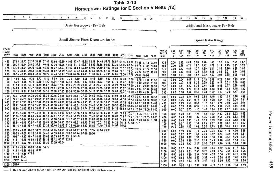
Table
3-1
3
Horsepower
Ratings
for
E
Section
v
Belts
11
21
I
5
b
'
8
3
10
I1
12
I3
I4
I5
16
I!
10
19
20
i 21
22
23
24
25
26
27
'28
29
Y)
Additional
Honepower Per
Belt
Basic
Horsepower
A
Per
Belt
c
\
r
7
Small
Sheave
Pitch
Diameter.
inches
Speed
Ratio
Range
A
f
/
7
435
485
575
585
690
50
100
150
200
250
300
350
400
450
500
550
600
650
700
750
800
850
900
950
I050
1100
1150
IO00
27.04 29.73
29.24
32.14
32.19
36.04
33.15
36.44
36.55 40.15
452 4.92
8.21 8.96
11.56 12.65
14.68
16.08
17.61 19.31
20.37 22.36
22.97 25.23
25.42 27.93
27.72 30.47
29.86 32.83
3185 35.02
3368 37.02
3535
38.84
36.84
40.46
38.16
41.88
39.29
43.08
46.72
50.20
53.51
56.65
59.61 62.38 64.97 67
36
69
55
71.53
73.30
800
0.00
0.59 1.17 1.76 2.35
2.94 3.52 411 470
5.26
40.23 44.07 47.73 51.19
54.46
57.53 60.39 63.02
65.44
6762 6956
850
0.00
0.62 1.25
1.8.7
2.49
3.12
3.74 4.37 4.99
5.61
40.97
44.83
48.47 51.89 55.08
58.03
60.73 63.18 65.36
900
0.00
0.66
132 1.98 264
3.30
3.96
4.63
5.29 5.94
41
51
45.35 48.94 52.27 55.33
58.12
M.62
62.82
950
0.00
0.70 1.39 2.10 2.79
3.49 1.18
488
5.58 6.27
4194 4564 49.01 5204
5472
1050
0.00
0.77 1.54
2
32 3.08
3
85
462
5.40 6.17 6.93
41.81 45.38 48.59
5140
1100
0.00
0.81
1.61
2.43 3.23 404
4.84
5.65
6.46
726
41.45
44.86
47.85
41.84
45.62 49.12 52.32 55.22 57.79
a04
1000
0.00
0.73
1.47 2.21 2.93 367 4.40 5.14
s.ea
6.60
iiw
ooo
084
169 2.54
3
37
4
22 5.06 5.91 6.76 7.60
32.37 34.98
35.00 37.81
39.23 42.35
39.66
42.80
43.64
47
02
5.32 5.12
9.71
10.46
13.73
14.80
17.47
1886
21.00 22.68
24.33 26.29
27.47 29.68
33.18 35.85
35.75 38.62
38.12
41.16
40.28 43.47
42.24 45.54
43.97 47.36
30.42 32.87
45.47 48.92
37.55 40.09 42.59
45.05
47.47 49.85 52.19 5419
45.39 48.37 51.27 54.09
56.84
59.50 62.09 64.59
50.29
53.44
56.47 59.38 62.16 6481 67.33 69.71
11.20 11.94 12.68
13.41
14.15 1487 15.60 16.32
15.87
16.93 17.99 19.05 20.09
21.14
22.18 23.21
20.24
21
61
22.97 24.32 25.66 27.00 28.33 29.65
24.35 28.00 27.65 29.28 30.90 32.50
34.10
35.68
21
72
30
15
32
05
33.94
35.81
37.67 39
50
41.32
40.58 43.29 45.96
48.58
51.15 53.67 56.13 50.55
45.88 48.87 51.79
54.65
57.39
60.06
62.65 65.15
6.12 6.51 6.91 7.30 7.69
8.08
8.46
8.115
jiji
Koi
jiii
jiji
io.ii
i2.a
44.5i
46.56
38.48
41.08
43.63
46.14
48.61 51.04 55.42 55.76
35.29 37.69 40.05 42.38
44.68
46.95 49.18 51.38
41 43
44
20
46
92 49 58 52
18
54 74
57
23 59
67
44
14
47 05 49 90 52 67
55
38
58
02
60
59
63
08
46
51
49 61 52
55
55
41
58 19
6081
63
46
65
96
4sii
518s
5487
5777 6057
6326
6583 6828
5064
5380
5683 5974 6251
65
15 6765 7001
5223 5540 5842
61
28
6399 6653 6890
71
10
5675 58.Y7
61
15
6328
60
90
63
20 65
41
61
64
61
00
69
33
71 57
73
72
67 57 69 89 72
I1
74
24
7195 7405 7600 77lg
923 962
1000
1038
1704 1776 1841 1919
24 24 25 26
26
28 27
30
30
96 32 27
33
57
34
88
3726 3882 4031
4190
43
13
4491
4668
4143
48
56
50
54
52
50
54
42
53
55 55
68
57 78 59
84
58
05
60
30
62 50
64
65
6205
6436
6662
6881
65
6836
49 67 7067
83
70
:281
09
::
14s'
27
7062
7283
?;92
*6sa
7222
7313
7428 7497
7618
7662 17%
65
38
67
41
69.40
6916
71.93
7383
I
485
I
435
1577 77j2 7958
I
16
27
'8
20
80
53
1943
8090
1076
Ill4 1152
19 90
20
60
21
31
2831 2931
30.31
L
~
0
00
0
00
0
00
0
00
0
00
0
00
0
00
0
00
0
00
0
00
0
00
0 00
0
00
0
00
0
00
0
00
0
00
0
00
0
00
n
nn
-
-
-
0
32
0
36
0
42
0
43
0
51
0
04
0
07
0
11
0
15
0
22
0
26
0
29
0
33
0
37
0
40
0
44
0
48
051
-
o
ia
-
-
0.64
0.7 1
0.84
0.86
1.01
0.07
0.15
0.22
0.29
0.37
0.44
0.51
0
59
0.66
0.73
0.81
0.88
0
95
1.03
-
-
-
I
IO
0.96
1.01
1.27
1.29
1.52
0.11
0.22
0.33
0.44
0.55
0.66
0.77
0.88
0.99
1.10
121
1.32
1.43
1.54
165
_I
-
-
1.28
1.42
1.69
1.72
2.02
0.15
0.29
0.44
0.59
0.73
0.88
1.03
1.17
132
1.47
161
1.76
1.91
2.05
2.20
-
-
-
1.60
1.78
2.11
2.15
2.53
0.18
0.31
0.55
0.73
0.92
1.10
128
1.47
1.65
1.84
2.02
2.20
2.39
2.57
2
75
-
-
-
192
1.24
2.58
2.87
2.ii
i.49
2as 320
253
296
338
380
258
301
344
386
304
355
405 456
.._
.
~~
0.22
0.26
0.29
0.33
0.44
0.51
0.59
0.66
0.66
0.77
0.88
0.99
0.88
1.03
1
18
1.32
1.10
1.28 1.47
1.65
1.32
1.54 1.7s
1.98
154
1.80
2.06
2.31
1.76
2.06
2.35 2.64
2.20 2.51 2.94
3.30
2.42
2.83
3.23
3.63
2.64
3.01
3.53 3.98
2.86
3.34
3.82
4.29
3.08
3.60
4.11
4.62
3
30
3.85 4.41
4.95
1.911 2.31 2.64 2.91
1200
4083
4404
1200
000
on8
176
265
352
(41
528
617 705 793
1250 3997 4293
1250
000
092
183
276
367
159
550
642
734
826
1300
I
3884
113001
000
095 191 287
382
(77
572
668
764 859
7
Rom
Speed
Above
6000
Feet
Per
MrnuIe
Soecial
Sheaves
May
Be
Necessary
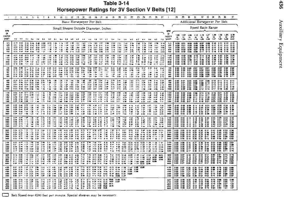
Table
3-1
4
Horsepower Ratings for
3V
Section
V
Belts
[12]
I
2
3
4
5
I
7
8
9
10
I1
12
I3
I4
I5
16
I1
18
19
m
21
22
23
24
25
26
21
I
28
29
30 31
I2
33
51
35
36
11
Basic
Horsepower Per Beti
Small Sheave
Outside
Dinmeter.
Inches
Additional Harsepwer Per I<eh
I
71
Speed
Ratio Range
>
'.
OF..'
rm
m
1.-
(12
1.1s
ut
us
,.m
1.s
is
'
RFn
RFit
Of
<
6
Q,
0
Belt
Speed
aver
fi5OO
feet
per
minute. Special sheaves
may
be
necessary
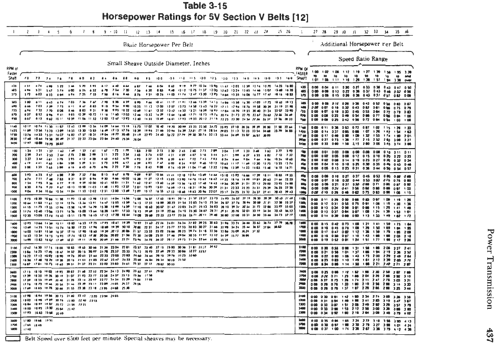
Table
3-1
5
Horsepower
Ratings
for
5V
Section
V
Belts
[12]
I
2
1
4
5
6
7
8
9.10
11
12
11
14
I5
16
17
in
19
20
21
22
il
24
25
26
I
27
21
2910
JI
12
11
34
15
J6
I
Additional Horsepower
rer
Belt
Basic
Horsepower Per Belt
L
I
\-
".
.
Small
Sheave Outside Diameter. Inches
*v
Speed
Ratio
Ranae
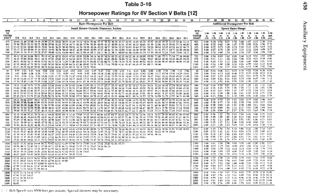
Table
3-16
Horsepower Ratings
for
8V
Section
V
Belts
[I21
t
Q,
I
2
3
4
3
6
7
8
Y
IO
II
12
IS
14
15
16
I7
18
IY
20
PI
PP
23
24 25
26
I
27
m
m
M
31
32
s3
51
55
36
Basic
Homepaver
Per
Belt
Additiond
Holaepwer
Per
Bell
r
Speed
Ratio
Rmge
,
RPM,
Srmll
Sheave
Ovtside
Dimmeter,
Inches
RPMr
Power Transmission
439
(text continued
from
page 429)
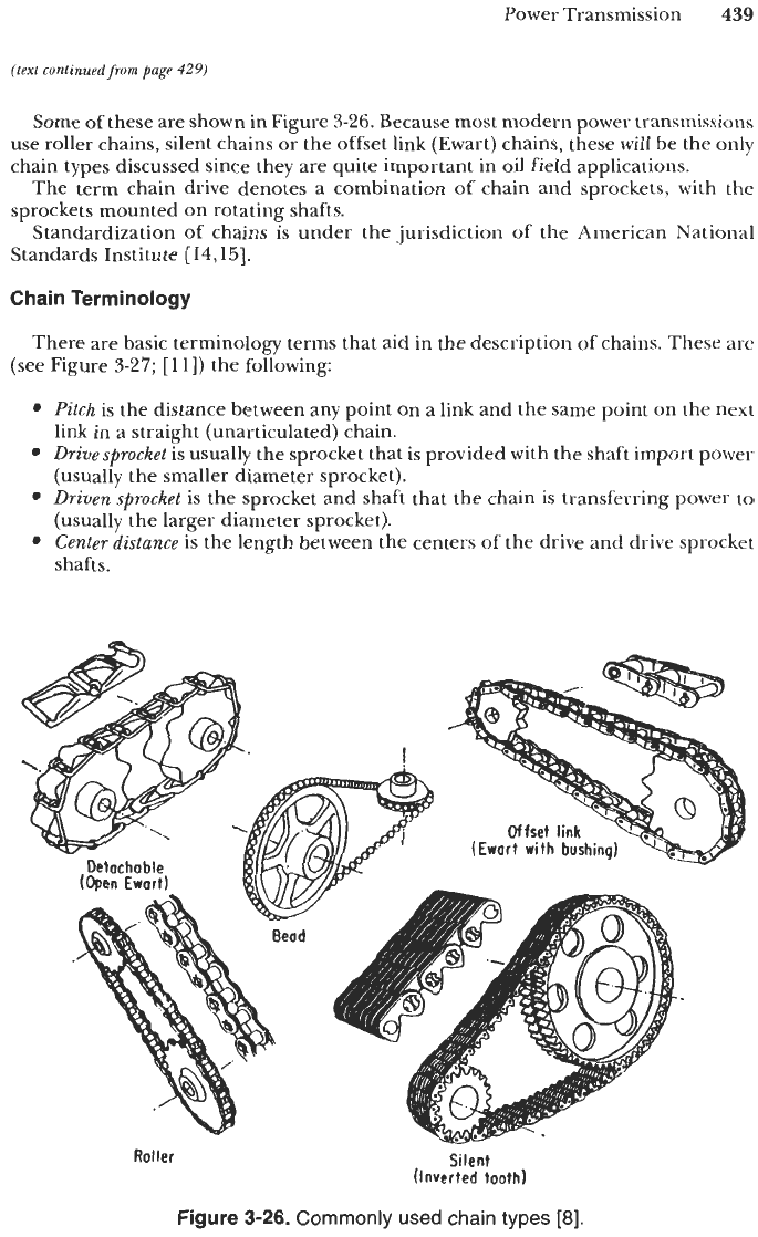
Some of these are shown in Figure
3-26.
Because most modern power transmissions
use roller chains, silent chains or the offset link (Ewart) chains, these will be the only
chain types discussed since they are quite important in oil field applications.
The term chain drive denotes a combination of chain and sprockets, with the
sprockets mounted on rotating shafts.
Standardization of chains is under the jurisdiction of the American National
Standards Institute
[14,15].
Chain Terminology
There are basic terminology terms that aid in the description of chains. These are
(see Figure
3-27;
[
111)
the following:
Pitch
is the distance between any point on a link and the same point on the next
Drivesprocket
is usually the sprocket that is provided with the shaft import power
Driven sprocket
is
the sprocket and shaft that the chain is transferring power to
Center distance
is the length between the centers of the drive and drive sprocket
link in a straight (unarticulated) chain.
(usually the smaller diameter sprocket).
(usually the larger diameter sprocket).
shafts.
Offset
link
(Ewart
with
bushina)
Roller
Silent
(Inverted tooth)
Figure
3-26.
Commonly used chain types
[8].
440
Auxiliary Equipment
Varies with
load,
length
of
strand. orientation with
gravity, arid extent
of
wear
I.-
c
Center distance
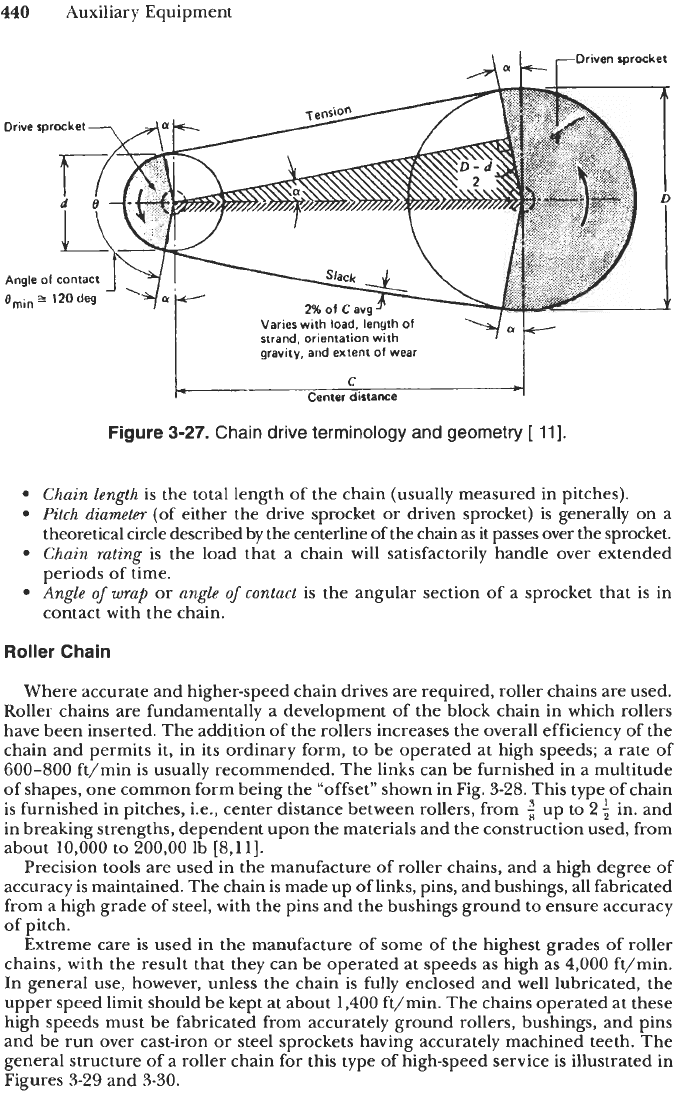
Figure
3-27.
Chain
drive
terminology
and
geometry
[
111.
Chain length
is the total length of the chain (usually measured in pitches).
Pitch
diameter
(of either the drive sprocket
or
driven sprocket) is generally on a
theoretical circle described by the centerline of the chain as it passes over
the
sprocket.
Chain
rating
is
the load that a chain will satisfactorily handle over extended
periods of time.
Angle
of
wrap
or
angle
of
contact
is
the angular section of a sprocket that is in
contact with the chain.
Roller
Chain
Where accurate and higher-speed chain drives are required, roller chains are used.
Roller chains are fundamentally a development of the block chain in which rollers
have been inserted. The addition of the rollers increases the overall efficiency of the
chain and permits it, in its ordinary form, to be operated at high speeds; a rate of
600-800
ft/min is usually recommended. The links can be furnished in a multitude
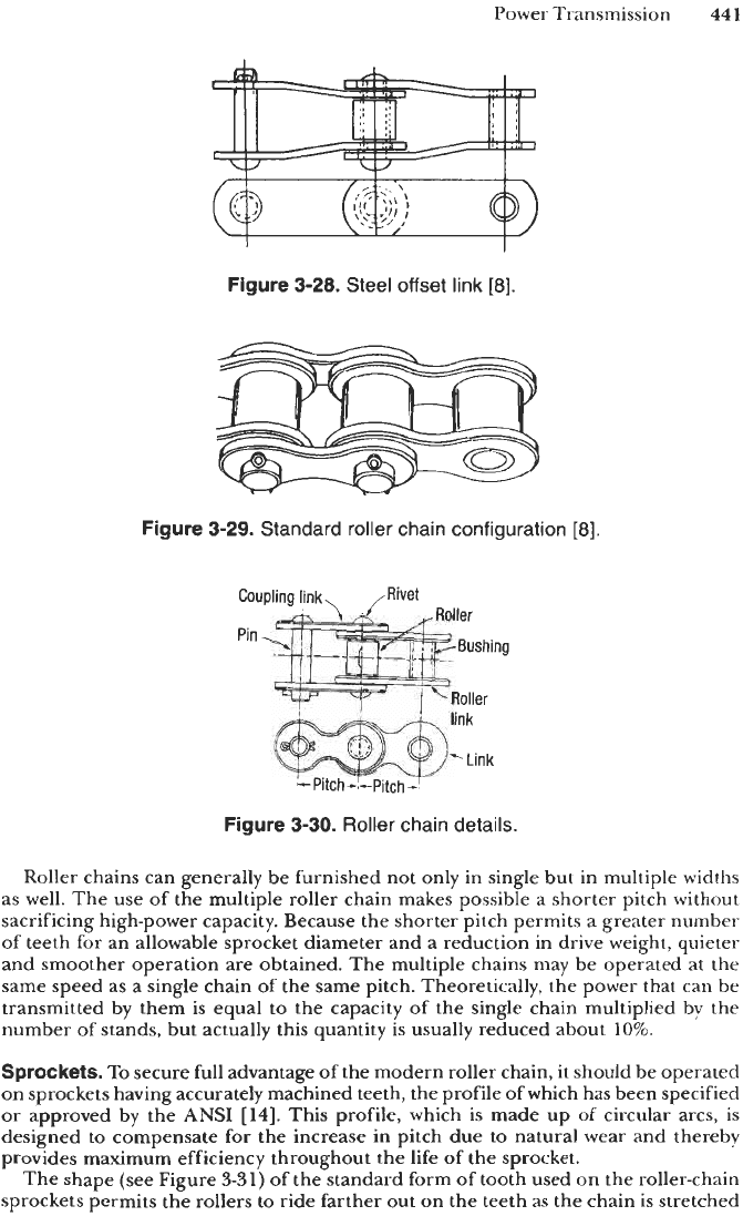
of shapes, one common form being the “offset” shown in Fig.
3-28.
This type of chain
is furnished in pitches, Le., center distance between rollers, from
{
up
to
2
f
in. and
in breaking strengths, dependent upon the materials and the construction used, from
about
10,000
to
200,OO
lb
[8,11].
Precision tools are used in the manufacture of roller chains, and a high degree of
accuracy is maintained. The chain is made up of links, pins, and bushings, all fabricated
from a high grade of steel, with the pins and the bushings ground to ensure accuracy
of pitch.
Extreme care
is
used in the manufacture of some of the highest grades of roller
chains, with the result that they can be operated at speeds as high as
4,000
ft/min.
In general use, however, unless the chain is fully enclosed and well lubricated, the
upper speed limit should be kept at about
1,400
ft/min. The chains operated at these
high speeds must be fabricated from accurately ground rollers, bushings, and pins
and be run over cast-iron
or
steel sprockets having accurately machined teeth. The
general structure of
a
roller chain for this type of high-speed service is illustrated in
Figures
3-29
and
3-30.
Power Transmission
441
Figure
3-28.
Steel offset
link
[8].
Figure
3-29.
Standard roller chain configuration
[8].
Figure
3-30.
Roller
chain details.
Roller chains can generally be furnished not only in single but in multiple widths
as well. The use of the multiple roller chain makes possible
a
shorter pitch without
sacrificing high-power capacity. Because the shorter pitch permits
a
greater number
of
teeth for an allowable sprocket diameter and a reduction in drive weight, quieter
and smoother operation are obtained. The multiple chains may be operated at the
same speed as a single chain
of
the same pitch. Theoretically, the power that can be
transmitted by them is equal
to
the capacity
of
the single chain multiplied by the
number
of
stands, but actually this quantity is usually reduced about
10%.
Sprockets.
To
secure full advantage of the modern roller chain, it should be operated
on sprockets having accurately machined teeth, the profile of which has been specified
or
approved by the
ANSI
[14].
This profile, which is made up
of
circular arcs, is
designed to compensate for the increase in pitch due to natural wear and thereby
provides maximum efficiency throughout the life of the sprocket.
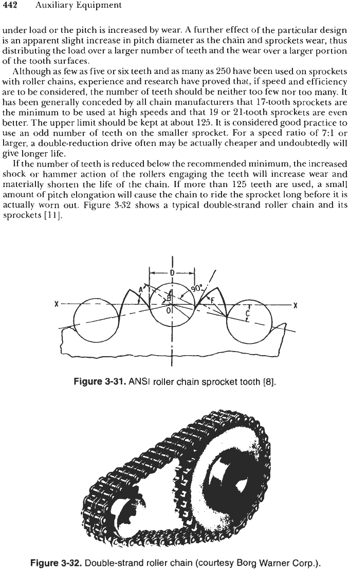
The shape (see Figure
3-31)
of
the standard form of tooth used on the roller-chain
sprockets permits the rollers
to
ride farther out on the teeth as the chain is stretched
442
Auxiliary Equipment
under load or the pitch is increased by wear. A further effect
of
the particular design
is an apparent slight increase in pitch diameter as the chain and sprockets wear, thus
distributing the load over a larger number of teeth and the wear over a larger portion
of the tooth surfaces.
Although as few as five or six teeth and as many as 250 have been used on sprockets
with roller chains, experience and research have proved that, if speed and efficiency
are to be considered, the number
of
teeth should be neither too few nor too many. It
has been generally conceded by all chain manufacturers that 17-tooth sprockets are
the minimum to be used at high speeds and that
19
or 21-tooth sprockets are even
better. The upper limit should be kept at about 125. It is considered good practice to
use an odd number
of
teeth on the smaller sprocket. For a speed ratio of 7:l or
larger, a double-reduction drive often may be actually cheaper and undoubtedly
will
give longer life.
If the number of teeth is reduced below the recommended minimum, the increased
shock or hammer action of the rollers engaging the teeth will increase wear and
materially shorten the life of the chain. If more than 125 teeth are used, a small
amount of pitch elongation will cause the chain to ride the sprocket long before it is
actually worn out. Figure 3-32 shows a typical double-strand roller chain and its
sprockets
[
1
11.
Figure
3-31.
ANSI
roller chain sprocket tooth
[8].
Figure
3-32.
Double-strand roller chain (courtesy Borg Warner Corp.).
Power Transmission
443
In general, four types of sprockets are available for roller chains. They are steel
plate without hubs, cast iron or steel with hubs on one or both sides, split type,
double-duty type.
The type of sprocket to be used depends entirely upon local or load conditions.
The steel plate without hubs is the cheapest and is furnished for bolting to suitable
hubs
or
flanges. The cast-iron or steel type fitted with hubs is made for direct mounting
upon shaft and is fastened in place by either keys or setscrews or a combination of
both. The split type is almost a necessity when the hub is mounted on a shaft with
other pulleys or sheaves. Its construction facilitates installation and removal, but
because of its extra cost it is usually not recommended except when solid hubs cannot
be installed. The double-duty sprockets are made with steel rims or plates that may
be removed
or
replaced without disturbing the hub, shaft, bearing, etc. Plates and
hubs can be obtained either solid or split. They are particularly adapted for jobs
requiring changing of drive ratios
or
where replacements must be made quickly.
Shaft
Centers.
It can be readily seen that on any chain drive the minimum center
distances must be more than one-half the sum of the diameters
of
the two sprocket
wheels. Experience has shown that best results are usually obtained when the center
distance between shafts is
30
to
50
times the chain pitch. Forty times the chain
pitch is about normal, and
80
times the pitch is maximum. In highly pulsating loads,
20
to
30
times the pitch is more nearly the correct center distance. Center distances
of 10-12 ft are permissible with finished steel roller chains operated at moderate
speeds without the use of idlers. On distances greater than this, an idler should be
used to eliminate the possibility of swaying or flopping, which may cause the chain to
jump the sprocket. When idlers are used, they should be placed on the slack strand
of
the chain, The number of teeth in the idler should be the largest possible and
preferably not less than the number in the smaller sprocket of the drive.
Silent Chain
The expression “silent chain” may be somewhat misleading, for the type of chain
which
it
is used to describe is not exactly silent, but it is much quieter in operation
than the roller chain. The essential features of the silent chain are the straight-sided
working jaws of the links, meshing with the straight-sided teeth
of
the sprocket, and
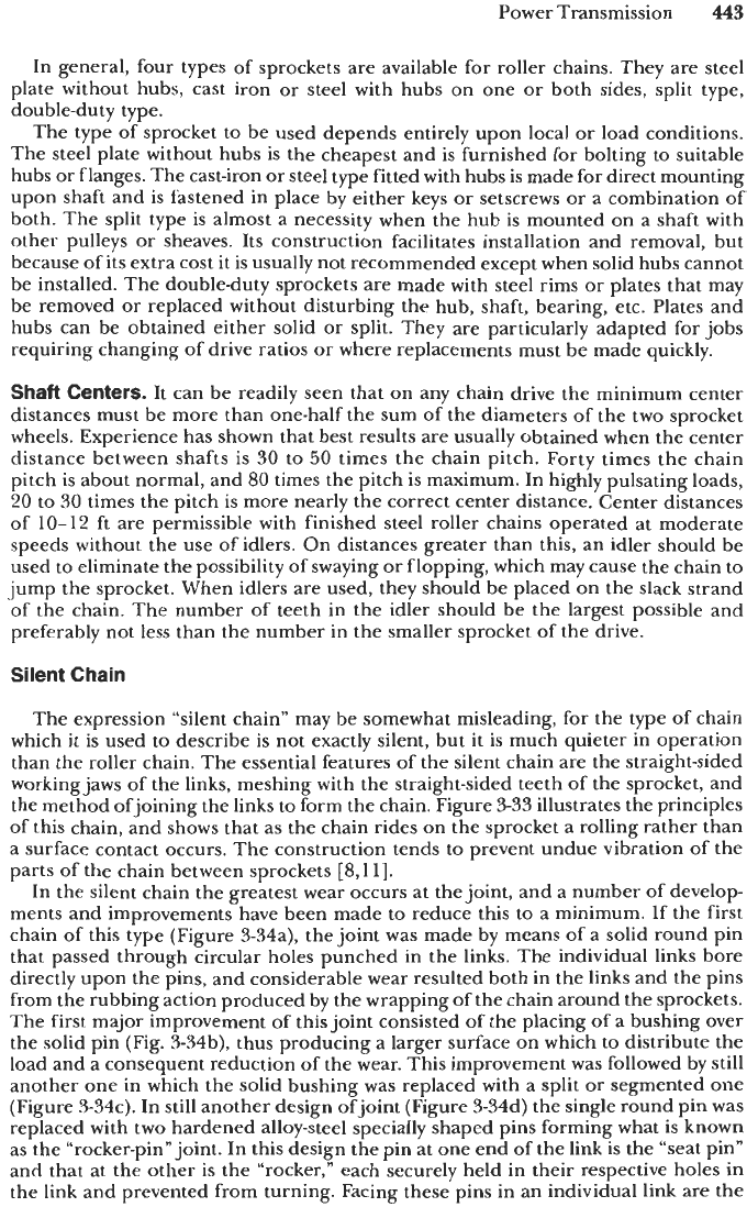
the method ofjoining the links to form the chain. Figure
3-33
illustrates the principles
of this chain, and shows that as the chain rides on the sprocket a rolling rather than
a surface contact occurs. The construction tends to prevent undue vibration of the
parts of the chain between sprockets
[8,11].
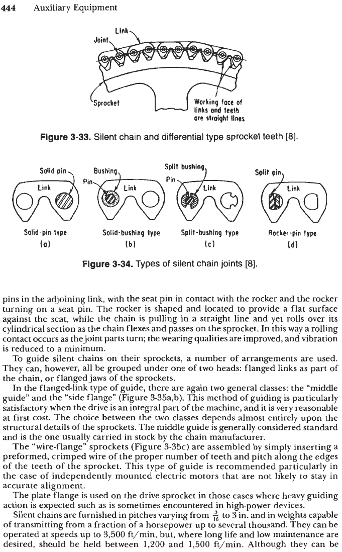
In the silent chain the greatest wear occurs at the joint, and a number of develop-
ments and improvements have been made to reduce this to a minimum.
If
the first
chain of this type (Figure 3-34a), the joint was made by means of a solid round pin
that passed through circular holes punched in the links. The individual links bore
directly upon the pins, and considerable wear resulted both in the links and the pins
from the rubbing action produced by the wrapping of the chain around the sprockets.
The first major improvement of this joint consisted
of
the placing of a bushing over
the solid pin (Fig. 3-34b), thus producing a larger surface on which to distribute the
load and a consequent reduction of the wear. This improvement was followed by still
another one in which the solid bushing was replaced with a split or segmented one
(Figure 3-34c). In still another design ofjoint (Figure 3-34d) the single round pin was
replaced with two hardened alloy-steel specially shaped pins forming what is known
as the “rocker-pin” joint. In this design the pin at one end of the link is the “seat pin”
and that at the other is the “rocker,” each securely held in their respective holes in
the link and prevented from turning. Facing these pins in
an
individual link are the
444
Auxiliary Equipment
Llnk.
Working face
of
links
ond teeth
ore
straight lines
‘Sprocket
W
Figure
3-33.
Silent
chain
and differential type sprocket teeth
[8].
Solid-pin type
Solid-
bushing type Split -bush tnq type Rocker-pin type
(a)
(b)
(C)
(d)
Figure
3-34.
Types
of
silent chain joints
[8].
pins in the adjoining link, with the seat pin in contact with the rocker and the rocker
turning on a seat pin. The rocker
is
shaped and located to provide a flat surface
against the seat, while the chain is pulling in a straight line and yet rolls over its
cylindrical section
as
the chain flexes and passes on the sprocket. In this way a rolling
contact occurs as the joint parts turn; the wearing qualities are improved, and vibration
is reduced to a minimum.
To guide silent chains on their sprockets, a number of arrangements are used.
They can, however, all be grouped under one of two heads: flanged links as part of
the chain, or flanged jaws of the sprockets.
In the flanged-link type of guide, there are again two general classes: the “middle
guide” and the “side flange” (Figure 3-35a,b). This method of guiding is particularly
satisfactory when the drive is an integral part of the machine, and it is very reasonable
at first cost. The choice between the two classes depends almost entirely upon the
structural details of the sprockets. The middle guide is generally considered standard
and is the one usually carried in stock by the chain manufacturer.
The “wire-flange” sprockets (Figure 3-35c) are assembled by simply inserting a
preformed, crimped wire of the proper number of teeth and pitch along the edges
of the teeth of the sprocket. This type of guide
is
recommended particularly in
the case of independently mounted electric motors that are not likely to stay in
accurate alignment.
The plate flange
is
used on the drive sprocket in those cases where heavy guiding
action is expected such as is sometimes encountered in high-power devices.
Silent chains are furnished in pitches varying from
2
to
3
in. and in weights capable
of
transmitting from a fraction of a horsepower up to several thousand. They can be
operated at speeds up to 3,500 ft/min, but, where long life and low maintenance are
desired, should be held between
1,200
and
1,500
ft/min. Although they can be