Lyons W.C. (ed.). Standard handbook of petroleum and natural gas engineering.2001- Volume 1
Подождите немного. Документ загружается.

Power
Transmission
455
0.34
0.43
0.52
0.70
0.61
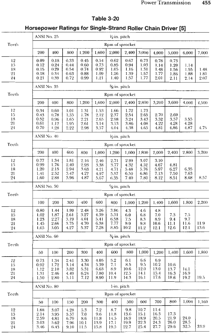
Table
3-20
Horsepower Ratings
for
Single-Strand Roller Chain
Driver
[5]
0.60
1.01
1.31
1.53 1.66 1.72 1.73
0.78 1.35 1.78
2.12 2.97 2.54 2.65 2.70 2.69
0.96 1.6.5 2.21 2.65 2.98 3.24 3.43 3.52 3.57 3.55
1.28 2.22 2.98 3.57 4.04
4.38
4.65 4.81 4.86 4.87 4.75
1.12 1.95 2.61 3.14 3.53
3.86
4.08 4.22 4.28 4.28
ANSI
No.
25
%-in. uitch
100 200 300 400 600 800 1,000 1,200 1,400 1,600 1.800
0.80 1.44
1.99 2.48
3.26 3.86 4.3
4.6 4.8
1.02 1.87
2.61 3.27
4.39 5.31 6.0
6.8 7.0 7.3 7.5
1.23 2.27
3.19 4.01
5.41 6.58 7.5
8.3 8.9 9.4 9.7
1.45
2.66 3.75
4.70
6.38 7.77
8.9 9.8
10.6
11.1
11.6
1.65
3.05 4.27
5.37
7.28
8.85
10.2
11.2 12.1 12.6 12.1
Teeth
2,200
11.9
13.6
Rpm
of
sprocket
50
0.73
0.92
1.12
1.31
1.50
100 200 300 400
600
800 1,000 1,200 1,400 1,600 1,800
1.34 2.41
3.30
4.05
5.2 6.1
6.6 6.9
1.7'2
3.14
4.34
3.39
7.1
8.5
9.5 10.2 10.6
2.10 3.82
5.31
6.63 8.9
10.6
12.0 13.0 13.7 14.1
2.46 4.49 6.24 7.80 10.4
12.5
14.1
15.4 16.3 16.9
2.80
j.11
7.12
8.90 11.9
14.3
16.1 17.6 18.6 19.2
193
50
1.68
2.14
2.59
3.03
3.46
100 150 200 300 400 500 600 700 800 1,000 1.160
3.07
4.28 5.3 7.2
8.7 9.8
10.7 11.4
3.95 5.57
7.0 9.6
11.8
13.6
15.1 16.3 17.3
4.81 6.79
8.6
11.8 14.5
16.9 18.9
20.5 21.9 24.0
5.62 7.96
10.1
13.9 17.1 19.9
22.3 24.3 26.0 28.5
6.43
9.10
11.5
15.8 19.5
255.7
25.4 27.7 29.6 32.5 33.9
200
I
400
I
800
12
I
.i
18
21
24
0.45
I
0.54
I
0.62
I
0.67
I
0.73
I
0.78
I
0.73
I I
0.60
0.73 0.85 0.94 1.03 1.14
1.20 1.14
0.74
I
0.92
I
1.05
I
1.16
I
1.31
I
1.48
I
1.56
I
1.55
I
1.48
0.88
1.09 1.26 1.39 1.57 1.77
1.86
1.88
1.81
0.99
1.21 1.40 1.57 1.77 2.01 2.11 2.14 2.07
%-in. uitch
ANSI
No.
35
Rpm
of
sprocket
Tcwth
12
1
r,
18
21
24
Rprn
of
sprocket Teeth
200
I
100
I
600
I
800
I
1,000
I
1,200
I
1,600
I
1,800
I
2,000
I
2,400
I
2,800
I
3,200
12
15
I8
21
24
0.77
I
1.34
I
1.81
I
2.16
I
2.46
I
2.71
I
2.99
I
3.07
I
3.10
I I
I
1.60
I
2.88
I
3.96
I
4.87
I
5.67
I
6.35
I
7.40
I
7.80
I
8.12
I
8.51
I
8.68
I
8.57
ANSI
No.
50
%in. pitch
Teeth
12
15
18
21
24
Teeth
12
I5
18
21
24
ANSI
No.
80
I-in.
uitch
Rnm
of
Fnrorkpr
Teeth
12
15
18
21
24
456
Auxiliary
EqGpment
15.6
21.3
26.6
31.4
35.4
Table
3-20
(continued)
4NSI
No. 100 l&n.
pitch
17.2
24.0 27.2 28.1
30.2 34.5 35.7
35.7 40.9 42.3
40.5 46.5 48.1
Teeth
20 30 50 100 150
200
250 300 350
3.72 5.4 8.4
14.8 20.1 24.5
28.1 31.0
4.73 6.9 10.8
19.3 26.6
32.8
38.2 42.8 46.7
5.73 8.3 13.1
23.7 32.7 40.5 47.3 53.2 58.4
6.70 9.7 15.3
27.7 38.4 47.6
55.7 62.8 69.0
7.65 11.1 17.5
31.7 43.7 54.3
63.6 71.6
78.7
1
400 450 475
62.9
74.5 79.0
84.8 89.9 92.4
im
of
sprocket
2.9
3.7
4.4
5.2
5.9
5.5
10.1 18.0 24.6 30.1 34.8 38.6
7.0 13.0 23.5 32.4
40.2
47.0 52.9 58.0 62.4
8.5 15.8
28.7 39.7 49.5
58.1 65.7 72.4 78.3
9.9 18.5
33.6 46.7 58.1
68.3 77.5 85.5 92.5 99
11.3 21.1 38.4 53.5 66.5 78.0 88.3 97.4 105.4 112 118
10 20 40 60
80
100 140 180 220 260 300
4.09
5.19
6.27
7.33
8.38
7.72 14.2 19.9 25.0 29.7
33.7 44.4
9.84 18.3 25.8 32.7 39.0
50.2 59.8
68.1
11.9 22.1
31.4 39.9 47.7
61.8 73.9 84.5
14.0 26.0
36.9 47.0
56.3
73.0 87.6 100.3
15.9 29.7 42.1 53.6 64.7
83.2 99.7 114.2
93.7
111.4
126.9
121.1
137.7
400
I
500
I
650
700
12
15
18
21
24
17.5
16.0 21.6
18.9 25.5
21.5 29.2
44.6
:!::
I
I
49.5
50.6 52.0
ANSI
No.
120
lJ+in.
pitch
Teeth
-
400
-
500
-
600
Rpm
of
sprocket
25
I
50
1
75
I
100
I
150
I
200
I
250
I
300
I
350
24.3
33.9
42.4
50.0
57.1
38.0
12
15
18
21
24
47.9
56.7
64.6
61.7
70.3
-
ANSI
No.
140
lV,in.
pitch
Teeth
12
15
18
21
24
ANSI No. 160
2-in. pitch
Teeth
Rpm
of
sprocket
10
1
20
I
40
I
80
1
120
I
160
I
200
I
240
I
280
I
320
I
360
I
400
12
15
18
21
24
ANSI
NO.
1x0
ZK-in. Ditch
Teeth
-
330
12
15
18
21
145.0
-
24
1
Teeth
-
280
-
173
Rpm
of
sprocket
5.6 10.5 19.1 26.8 33.6 39.6 45.1 54.4
13.4 24.7 34.8 43.9 52.2 59.8 73.4
8.6 16.2 30.0 42.4 53.7 64.1 73.7 90.7 105
10.0 18.9 35.1 49.7 63.1 75.3 86.6 106.9 124
11.4 21.6 40.2 56.8 71.9 86.0 98.8 121.8 142
12
15
18
21
24
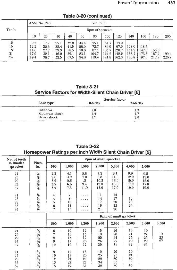
Power
Transmission
457
Table 3-20 (continued)
Teeth
12
15
18
21
24
I
ANSI
No.
240
%in.
pitch
Rpm
of
sprocket
10 20 30 40 60 80 100 120 140 160 180
9.5 17.7 25.1 32.0 44.4 55.1 64.7 73.0
12.2 22.6
32.4 41.5
58.0
72.7 86.9 97.9 108.0 118.5
14.6 27.7 39.3 50.5
70.8
87.1 105.7 120.7 134.5
147.0 158.0
17.0 32.1
46.0 59.1
83.1
104.7 124.2 142.2 158.7 173.5 187.2
19.4 36.7 52.5 67.5
94.8 119.4 141.8 162.3 180.8 197.6 212.9
21
25
29
33
37
200
-
199.4
226.9
-
Sg
Sg
38
se
%
Table 3-21
Service Factors for Width-Silent Chain Driver
[5]
Service factor
Load
type
10-h
day
24h
day
Uniform
1
.o
1.3
Moderate
shock
1.4 1.7
Heavy
shock
1.7 2.0
7.2
8.8
10.3
12.0
13.0
11
14
17
19
21
Table 3-22
HorseDower Ratings per Inch Width Silent Chain Driver
[5]
9.1
11.0
13.0
15.0
17.0
13
17
20
23
26
No.
of
teeth
sprocket
9.9
12.0
15.0
17.0
19.0
9.5
12.0
15.0
17.0
19.0
500
1,000
1,200
1,800
2,000
2,500
3,000
6
10
12
15
16 16 16
7 13
15
19 20 21 21
8
15
17
22 24 25 25
9
17
20 26 27 29 29
10 19
22 29 31 34 33
8
14 16 19 20 19
17 20 25 25 24
10
24 29 30 30
12 21
13 24 27 34 35 35
15 27 31 38 39 39
-
500
3,500
19
23
27
2.2
2.6
3.0
3.5
3.9
4
4
5
6
7
-
21
25
29
33
37
1,000
%
a/,
%
%
%
4.1
4.9
5.8
6.6
7.3
7
8
10
11
13
-
Rpm
of
small
sprocket
-
1,500
5.8
7.0
.2
9.4
11.0
....
,...
....
....
....
-
2,000
I
3,000
4,000
[
5,000
1
23
Rpm
of
small
sprocket
458
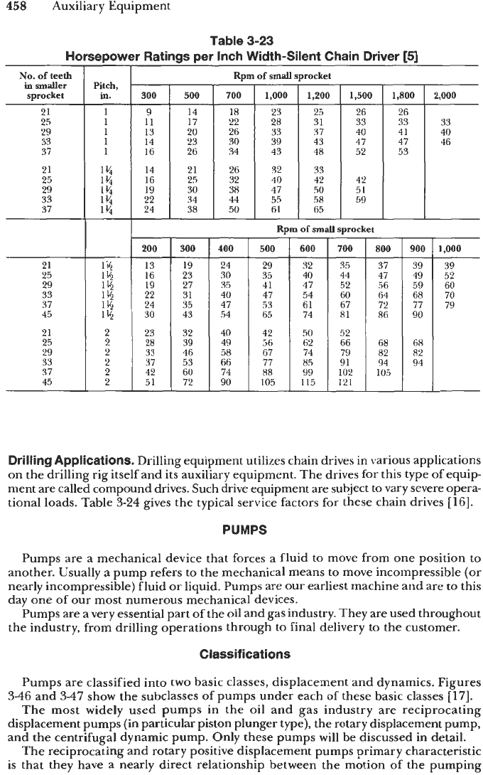
Auxiliary Equipment
Table
3-23
Horsepower Ratings per Inch Width-Silent Chain
Driver
[5]
No.
of
teeth
in
smaller
sprocket
21
25
29
33
37
21
25
29
33
37
21
25
29
33
37
45
21
25
29
33
37
45
Pitch,
in.
Rpm
of
small
sprocket
14
16
14
1
21
I
26
1
32
1
33
1
42
60
74
51
I
72
I
90
Rpm
of
small
sprocket
1,800
26
33
41
47
53
54
53
54
53
42
I
50
I
52
I
88 99 102
105
105
I
115
I
121
1
-
900
39
49
59
68
77
90
-
68
82
94
-
2,000
33
40
46
1,000
39
52
60
70
79
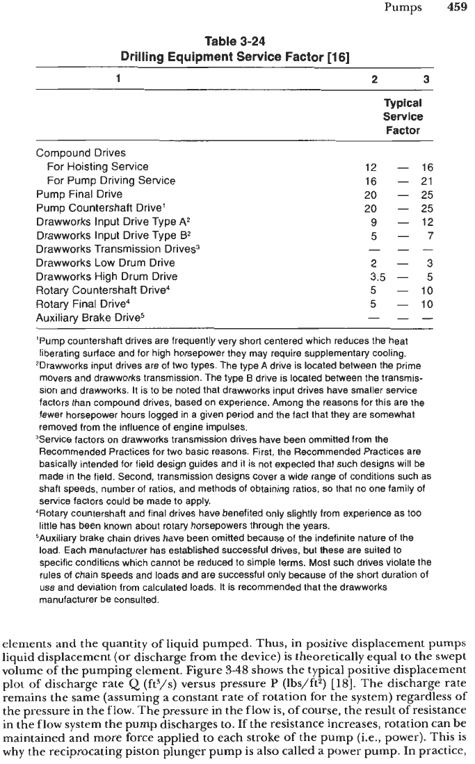
Drilling Applications.
Drilling equipment utilizes chain drives in various applications
on the drilling rig itself and its auxiliary equipment. The drives for this type of equip-
ment are called compound drives. Such drive equipment are subject to vary severe opera-
tional loads. Table
3-24
gives the typical service factors for these chain drives
[16].
PUMPS
Pumps are a mechanical device that forces a fluid to move from one position to
another. Usually
a
pump refers to the mechanical means to move incompressible (or
nearly incompressible) fluid or liquid. Pumps are our earliest machine and are to this
day one of
our
most numerous mechanical devices.
Pumps are a very essential part of the oil and gas industry. They are used throughout
the industry, from drilling operations through to final delivery to the customer.
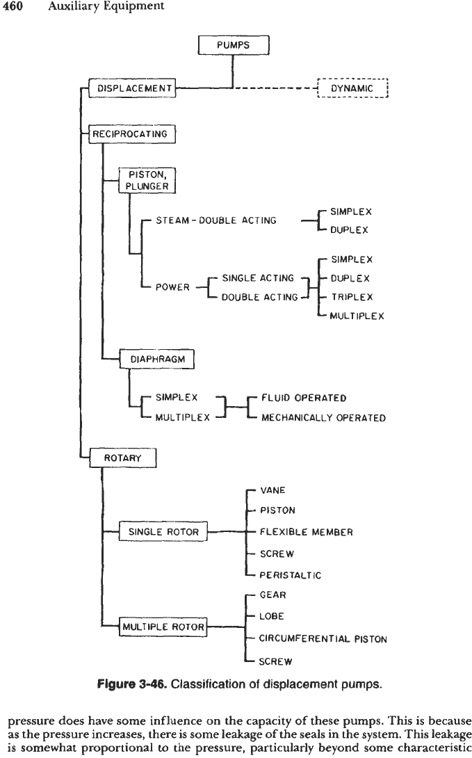
Classifications
Pumps are classified into two basic classes, displacement and dynamics. Figures
3-46
and
3-47
show the subclasses
of
pumps under each of these basic classes
[17].
The most widely used pumps in the oil and gas industry are reciprocating
displacement pumps (in particular piston plunger type), the rotary displacement pump,
and the centrifugal dynamic pump. Only these pumps will be discussed in detail.
The reciprocating and rotary positive displacement pumps primary characteristic
is that they have a nearly direct relationship between the motion
of
the pumping
Pumps
459
Table
3-24
Drilling Equipment Service Factor
[16]
1 2
3
Typical
Service
Factor
Compound Drives
For Hoisting Service
For Pump Driving Service
Pump
Final
Drive
Pump
Countershaft
Drive'
Drawworks
Input
Drive
Type
A*
Drawworks
Input
Drive
Type
B2
Drawworks Transmission Drives3
Drawworks Low Drum Drive
Drawworks High
Drum
Drive
Rotary Countershaft Drive4
Rotary
Final
Drive4
Auxiliarv
Brake
Drive5
12
-
16
16
-
21
20
-
25
20
-
25
9
-
12
5-
7
2-
3
3.5
-
5
5
-
10
5
-
10
-
--
-
--
'Pump countershaft drives are frequently very short centered which reduces the heat
liberating surface and for high horsepower they may require supplementaty cooling.
2Drawworks input drives are of two types. The type A drive is located between the prime
movers and drawworks transmission. The type
B
drive is located between the transmis-
sion and drawworks. It is
to
be noted that drawworks input drives have smaller service
factors than compound drives, based on experience. Among the reasons for this are the
fewer horsepower hours logged in a given period and the fact that they are somewhat
removed from the influence of engine impulses.
3Servi~e factors on drawworks transmission drives have been ommitted from the
Recommended Practices for
two
basic reasons. First, the Recommended Practices are
basically intended for field design guides and it is not expected that such designs will be
made in the field. Second, transmission designs cover a wide range of conditions such as
shaft speeds, number of ratios, and methods of obtaining ratios,
so
that no one family
of
service factors could be made to apply.
4R~tary countershaft and final drives have benefited only slightly from experience as too
little has been known about rotary horsepowers through the years.
5Auxiliary brake chain drives have been omitted because of the indefinite nature of the
load. Each manufacturer has established successful drives, but these are suited to
specific conditions which cannot be reduced to simple terms. Most such drives violate the
rules of chain speeds and loads and are successful only because of the short duration of
use
and deviation from calculated loads. It is recommended that the drawworks
manufacturer be consulted.
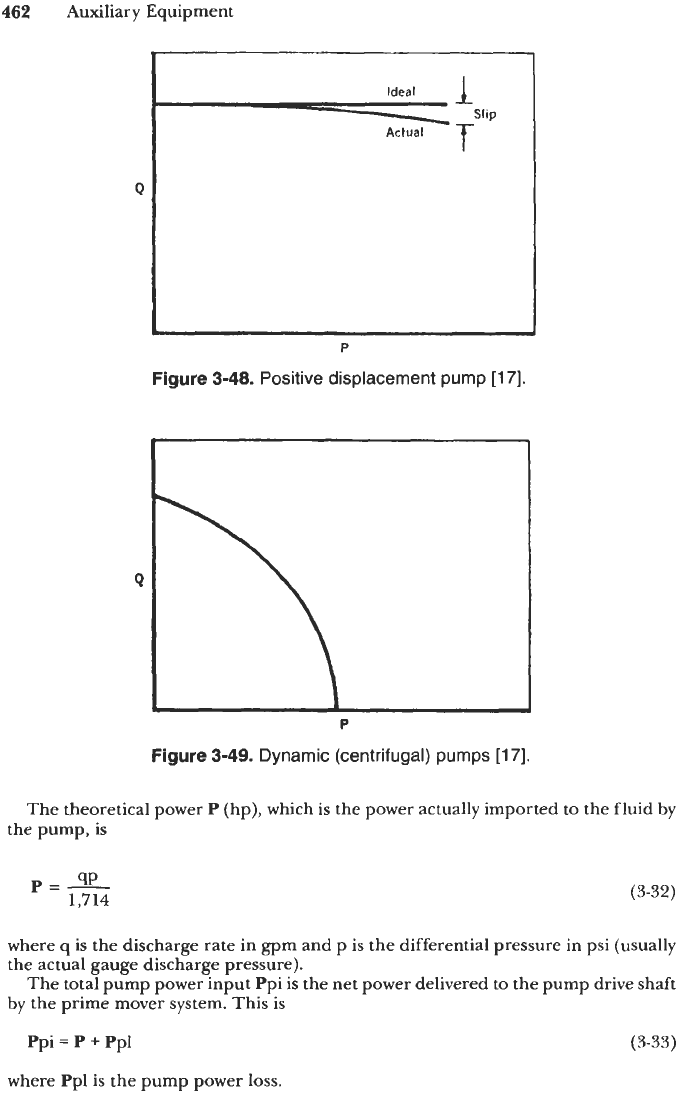
elements and the quantity of liquid pumped. Thus, in positive displacement pumps
liquid displacement
(or
discharge from the device) is theoretically equal to the swept
volume of the pumping element. Figure
3-48
shows the typical positive displacement
plot
of
discharge rate
Q
(fP/s) versus pressure P (lbs/ft2)
[HI.
The discharge rate
remains the same (assuming a constant rate of rotation for the system) regardless
of
the pressure in the flow. The pressure in the
flow
is,
of
course, the result of resistance
in the flow system the pump discharges to. If the resistance increases, rotation can be
maintained and more force applied
to
each stroke
of
the pump (i.e., power). This
is
why the reciprocating piston plunger pump is also called a power pump. In practice,
460
Auxiliary Equipment
SIMPLEX
DUPLEX
STEAM
-
DOUBLE ACTING
I
Ir
r
SIMPLEX
DUPLEX
TRIPLEX
SINGLE ACTING
DOUBLE ACTING
MULTIPLEX
I
DIAPHRAGM
LF’
FLUID OPERATED
MECHANICALLY OPERATED
ROTARY
-
VANE
-
PISTON
f
SINGLE
ROTOR
1
FLEXIBLE MEMBER
-
SCREW
-
PERISTALTIC
-
GEAR
-
LOBE
-
CIRCUMFERENTIAL PISTON
-
SCREW
Figure
3-46.
Classification of displacement pumps.
pressure does have some influence on the capacity
of
these pumps. This
is
because
as the pressure increases, there
is
some leakage
of
the seals in the system. This leakage
is somewhat proportional
to
the
pressure, particularly beyond some characteristic
Pumps
461
-
-
AXIAL FLOW
F
SINGLE STAGE CLOSED IMPELLER
FIXED PITCH
MULTISTAGE
H
OPEN IMPELLER
SEMI-OPEN
IMPELLER
CLOSED
IMPELLER
SINGLE STAGE
MULTISTAGE
SUCTION
r
JET
GAS LIFT
HYDRAULIC
RAM
L
ELECTROMAGNETIC
Figure
3-47.
Classification of dynamic
pumps
[17].
pressure related to the seals. The difference between theoretical flow and the actual
flow
of
a
pump is often referred
to
as slip. This slip is shown in Figure
348.
In the dynamic pump, in particular, the centrifugal pump, the discharge rate
Q
is
determined
by
the resistance pressure
P
in the flow system the pump discharges
to
(assuming some given speed of the pump). This
is
illustrated in Figure
3-49.
General Calculations
There are several important calculations that are needed to properly evaluate and
select the appropriate positive displacement pump
[
17,18,19,20,21].
462
Auxiliary Equipment
I
I
Q
1
P
Figure
3-48.
Positive
displacement pump
[17].
Q
P
Figure
3-49.
Dynamic (centrifugal) pumps
[17].
The theoretical power
P
(hp), which
is
the power actually imported to the fluid by
the pump,
is
p=-
9P
1,714
(3-32)
where
q
is the discharge rate in
gpm
and p
is
the differential pressure
in
psi (usually
the actual gauge discharge pressure).
The total pump power input Ppi is the net power delivered to the pump drive shaft
by the prime mover system. This is
Ppi
=
P
+
Ppl
(3-33)
where Ppl
is
the pump power
loss.
Pumps
463
The total power input Pti is the net power delivered by the prime mover. This is
Pti
=
Ppi
+
Ppml
where Ppml is the prime mover
loss.
Overall efficiency
e,
is
P
e,
=
-
Pti
usually multiplied by
100
and expressed as a percentage.
Pump efficiency ep is
P
ep
=
-
Ppi
(3-34)
(3-35)
(3-36)
(usually expressed as a percentage).
to supply power to the pump) is
Mechanical efficiency
e,,,
(which usually refers to the efficiency of the prime mover
Ppi
e,"
=
-
Pti
(3-37)
(usually expressed as a percentage).
Reciprocating Pumps
The piston plunger pump is the simplest form of a positive displacement pump.
These pumps can be powered by a variety of prime movers, internal combustion
engines, and electric motors (and in some cases, powered by a gas turbine motor). In
such applications, the separate pump unit is connected to the prime mover by a
power transmission.
The capacity of a pump is determined by the number of plungers
or
pistons and
the size
of
these elements (bore and stroke).
A
reciprocating pump is usually designed
for a specific volumetric rate capacity and pressure capability. These factors are set
by the application. Once the volumetric rate capacity and pressure capability are
known, a designer can determine the plunger piston bore and stroke the rotation
speed range and the power of the prime mover needed to complete the system.
Reciprocating pumps are fabricated in both horizontal and vertical configurations.
Single-Acting
Pump
A
single-acting pump has
only
one power (and discharge) stroke for its pistons.
Such a pump brings fluid into its chamber through the inlet
or
suction value
or
the
piston
is
drawn backward to open the chamber.
To
discharge the fluid, the inlet valve
is closed and the outlet valve opened as the piston is forced forward to push the fluid
from the chamber into the discharge line. The piston motion is accomplished by a
rotating crankshaft that is connected to the piston by a piston
rod
much like an internal
combustion piston engine. The rotating crankshaft of the pump is rotated by the
rotational power of the prime mover (through a transmission)
[21].
464
Auxiliary Equipment
The single-action pump is usually available with three, five and even seven pistons.
The odd number of pistons allows the pump to be rotationally balanced, and the use
of at least three pistons reduces the discharge pulsation of these single-acting pumps.
A
three piston pump single-action pump
is
called a triplex pump.
A
five piston, or
seven piston single-acting pump is called a multiplex pump.
Double-Acting Pump
Double-acting pumps have two power strokes.
As
a piston of the pump is pushed
forward, the fluid is discharged from the forward chamber into the discharge line
(much like a single-action piston). But during this same stroke, the chamber behind
the piston (which contains the connecting rod) is being filled via that chamber’s inlet
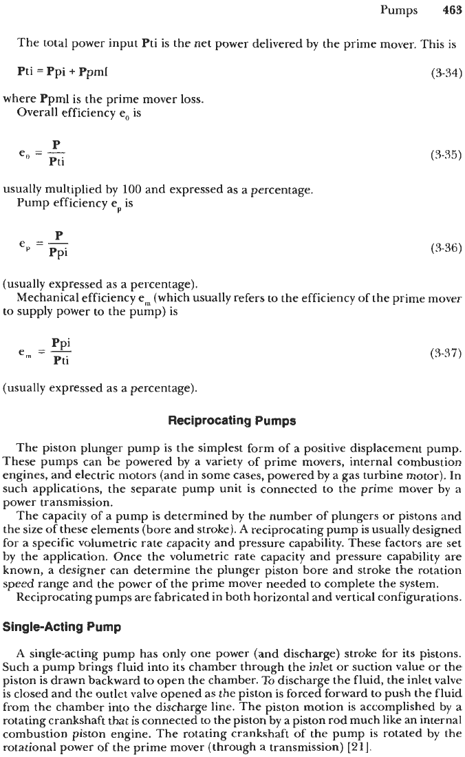
valve (see Figure
3-50).
When the forward power stroke is complete and the fluid
discharged from the chamber in front of the piston, the chamber behind the piston is
filled. The crankshaft continues to rotate, requiring the piston to begin a rearward
stroke. During this stroke the fluid behind the piston is forced from its chamber into
the discharge line via the outlet valve and the chamber in front of the piston refills
via its inlet valve
[21].
Double-acting pumps are usually available with one or two pistons.
A
one-piston double-action pump is called a
double-acting simplex
(since there are
A
two piston double-action pump is called a
duplex pump.
older single-action steam and pneumatic driven simplex pumps).
Flow
Characteristics
All reciprocating pumps have a pulsating discharge. This is the result of the piston
motion as it stops and reverses. At this moment, the flow from that piston theoretically
drops to zero. Thus, the discharge curves as a function of time are those illustrated in
Figure
3-51.
By
having two or more pistons the pulsation of the discharge from the
pump can be smoothed out and the magnitude of the pulsation reduced
if
the pistons
motions are timed for proper dynamic balancing of the pump (see Figure
3-52).
For
those pumps that have large pulsations, a cushion change (or accumulator) may be
used in the discharge line to reduce or eliminate the pulsations (see Figure
3-53).
Discharge Discharge Discharge
1
T
d,
La
Inlet
or
Sucbon Suction
Suction
PI
>::
Pi>::
(a) Double-achng (duplex) design
(b)
Single-acttng (tnplex) design
Figure
3-50.
Schematic
of
valve operation
of
single and double-acting pumps
[21].