Mark James E. (ed.). Physical Properties of Polymers Handbook
Подождите немного. Документ загружается.

therefore U
l-lim
¼ 0:300 J. If the impact energy determined
in the Charpy test (see the section on impact behavior) is
higher than this value, rapid crack propagation will not occur.
Since the criterion is defined for a class of polyethylenes, a
safety factor somewhat larger than unity may be introduced.
24.2.6 Slow Crack Propagation and Its Prediction
The slow crack propagation (SCP) is vastly different from
RCP, not at all spectacular but in fact ‘‘quiet’’ and insidious.
The crack propagation rate dh/dt might be only, say, 1 mm
per month; an observation for instance two weeks after
installing a polymeric component might reveal nothing.
Experimentalists customarily present the dh/dt rates as a
function of the logarithmic stress intensity factor K
l
as
defined by Eq. (24.16); we now use h as the crack length
(as we did before) to differentiate it from the length L which
pertained to RCP. The problem clearly consisted in relating
dh/dt to K
l
. It was solved [49] by using the CRC approach in
conjunction with the Eq. (24.17) of fracture mechanics. The
problem was different than that of Griffith. He needed the
critical stress s
cr
above which crack propagation occurs for
a given crack length h. In our problem we need to know
whether the crack length is below a certain value, call it h
cr
,
so that the crack will not propagate [49]. We therefore
reformulate the Griffith Eq. (24.17) as
h
cr
¼ 2GE=ps
3
: (24:28)
By definition, the crack will propagate only when h > h
cr
.
This is not only a consequence of the CRC concept but also
supported by the molecular dynamics computer simulations
[50,51] showing that a crossover exists from the force field
region dominated by chain relaxation to one in which crack
propagation occurs.
Since notches with h < h
cr
do not cause crack propaga-
tion, it was only natural to assume
dh
dt
¼ b(h h
cr
) for h $ h
cr
, (24:29)
where b is a time-independent proportionality factor char-
acteristic for the material since it depends on CRC. We do
not have space here to provide details of the derivation; the
final result [49] is
log K
l
¼ (1=2) log (a
2
2GE)þ
(1=2) log [1 þ (1=bh
cr
)]dh=dt:
(24:30)
Equation (24.30) provides the desired connection between
K
l
and dh/dt. In the derivation both the stress level s and the
original crack length h
0
were used but both canceled out,
with the unexpected result that the crack propagation rate is
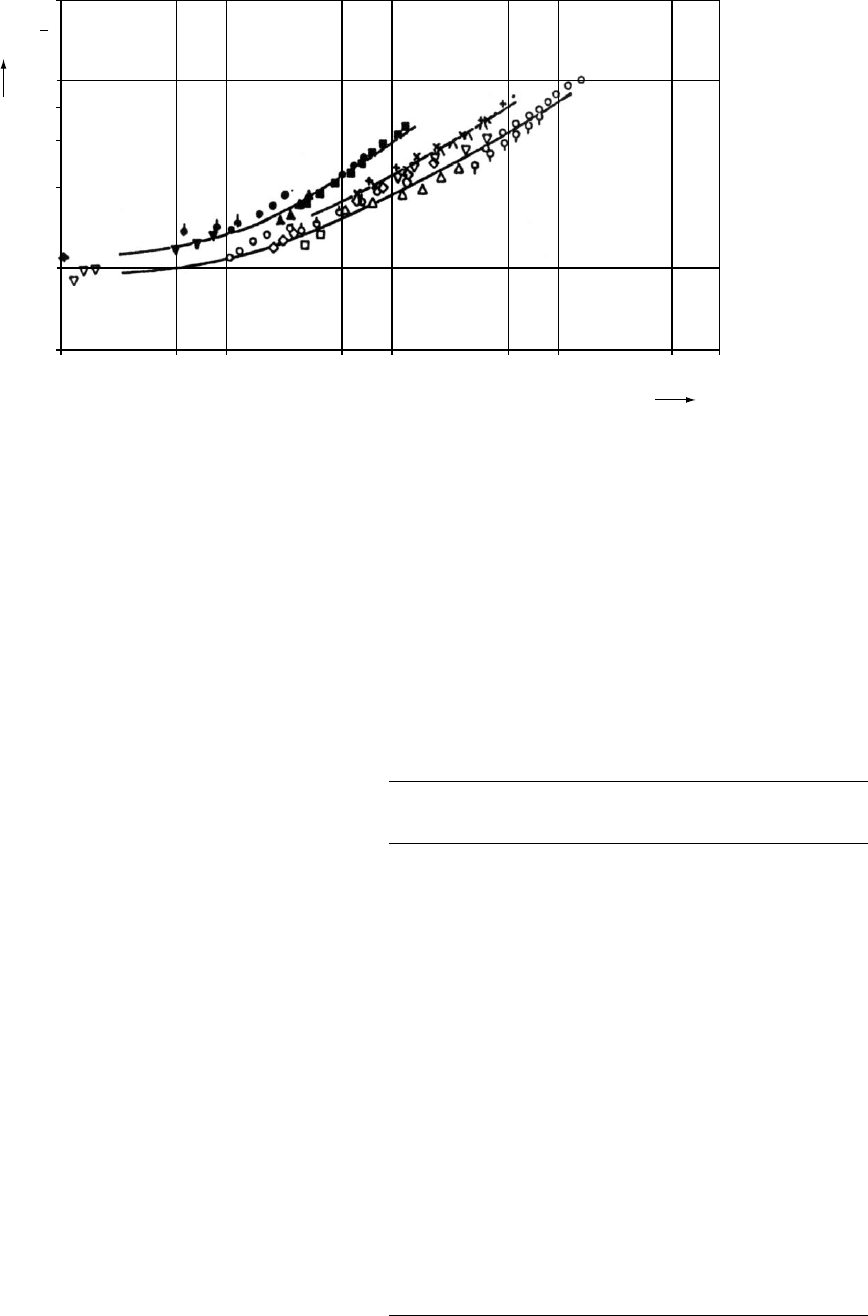
independent of both! The experimental results support Eq.
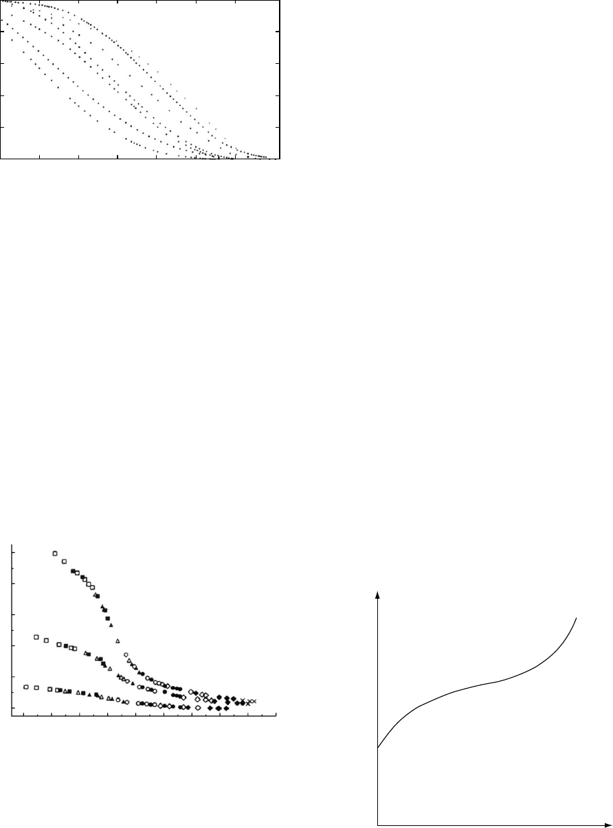
(24.30) as shown for instance in Fig. 24.3 for Hoechst PEs
studied under uniaxial tension in water medium at 60 8C.
Each symbol pertains to a different stress level and a differ-
ent original notch length. It is clear that all polyethylenes
with the molecular mass M
A
form a common curve, and the
same is true for the other molecular masses. Moreover, we
see that a higher M results in a lower crack propagation rate;
this result is related to the constituents of CRC listed at the
end of Section 24.1.3, particularly the first two of them.
In the beginning we have called SCP ‘‘insidious’’. The
lowest experimental crack propagation rate value in
Fig. 24.3 is dh=dt ¼ 10
8
cm s
1
; this is only 0.315 cm
per year, but the crack does grow. This fact gives us an
idea on the utility of Eq. (24.30).
24.3 QUASISTATIC TESTING AND TRANSIENT
TESTING
24.3.1 Types of Testing Procedures
We have already referred to various kinds of data on
mechanical behavior of polymers. We are now going to
consider methods of acquisition of such information. The
most frequently used are the so-called quasistatic methods
which involve relatively slow loading. Tension, compres-
sion, and flexure belong here. The quasistatic methods have
to be distinguished from so-called transient tests which
include stress relaxation and creep. There are also impact
tests and dynamic mechanical procedures which will be
defined later.
Specimens for testing may be produced by processing
operations such as injection molding, compression molding,
or machining from sheets. Machined surfaces have to be
smoothed in their long axis direction with abrasive paper.
Any flash on molded specimens shall be removed; the cross-
sectional area has to be uniform along the whole length
subjected to testing. Consequences of any nonuniformity
would show up as stress concentrators discussed above.
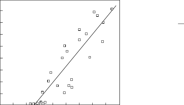
800
L/mm
700
600
500
400
300
200
100
0
23456
J/U
FIGURE 24.2. Length L/mm of the cracks in PE pipes
determined by the Greig-Smith test 50 vs. the reciprocal
Charpy impact energy (U=J)
1
; after [48].
MECHANICAL PROPERTIES / 429
The recommended number of tests on each sample is at least
five, 10 or more are preferred. If producing design data for a
particular application is the objective, the samples must be
prepared by the same method as the part in question.
Testing of materials is governed by standards. We shall
often refer below to those of the American Society for
Testing and Materials (ASTM), West Conshohocken, PA.
However, as national economies become more and more
connected into a global economy, the use of standards
defined by the International Standards Organization (ISO)
is on the increase. In Table 24.2 we list several ISO and
ASTM tests.
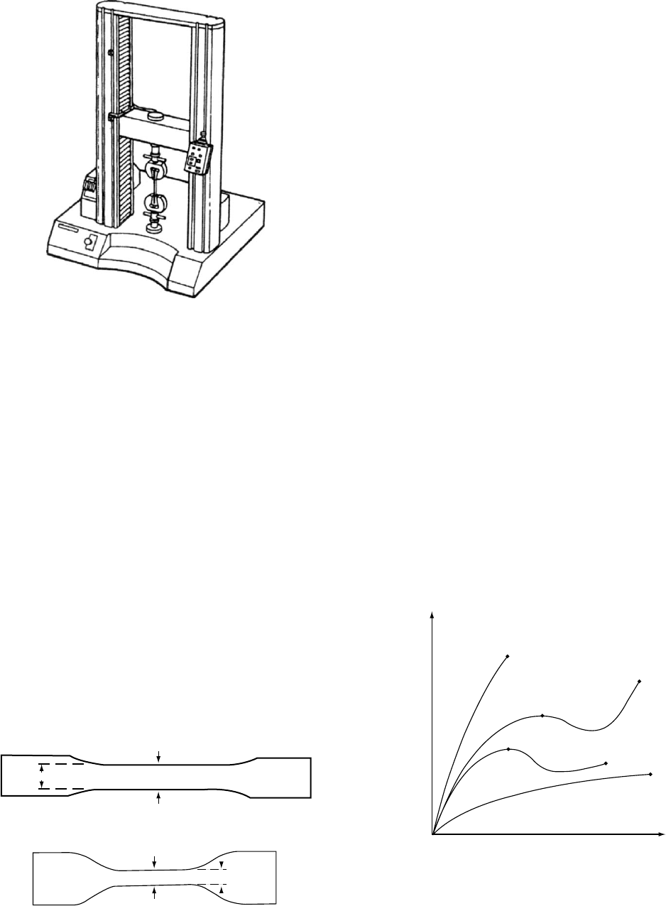
24.3.2 Tensile Properties
Tensile testing is the most frequently used method to
characterize the material strength. The machine used is pre-
sented schematically in Fig. 24.4. It should be of the con-
stant-rate-of-crosshead-movement type, consisting of one
fixed and one movable member, both carrying self-aligning
grips. The movable member shall move with a uniform,
controlled velocity with respect to the stationary one. An
extensometer is used to determine the distance between two
designated points within the gage length of the test specimen
as this is stretched. Speed of testing is defined as the relative
rate of motion of the grips or test fixtures. It is specified for
different types of specimens, varying typically from 1 to
500 mm/min (0:2---20 in: min
1
). The lowest speed that pro-
duces rupture in the time range 0.5–5 min for the specimen
geometry used is to be selected.
One tests dumbbell-shaped or straight-sided specimens
under defined conditions of pretreatment, temperature, hu-
midity, and deformation rate. The former specimens are
shown in Fig. 24.5.
There are two essential properties determined each time.
The first is the engineering stress
s ¼ F=A
0
, (24:31)
where F is the applied force and A
0
is the initial cross-
sectional area. Determination of the true stress based on
the actual cross-sectional area A which changes during the
TABLE 24.2. ISO and ASTM tests for important mechanical
properties.
Property
ISO
standard
ASTM
standard
Tensile modulus 527-1 & 2 D 638
Yield stress 527-1 & 2 D 638
Yield strain 527-1 & 2 D 638
Nominal strain at break 527-1 & 2 —
Elongation at break 527 D 638
Stress at 50% strain 527-1 & 2 —
Stress at break 527-1 & 2 D 638
Strain at break 527-1 & 2 D 638
Flexural modulus 178 D 790
Flexural strength 178 D 790
Charpy impact strength at 30 8C 179 D 256
Charpy impact strength at þ23 8C 179 D 256
Charpy notched impact
strength at 30 8C
179 D 256
Tensile impact 8256 D 1822
Izod impact strength at 30 8C 180 D 4812
Izod impact strength at þ23 8C 180 D 4812
Izod notched impact strength
at 30 8C
180 D 256
Izod notched impact strength
at þ23 8C
180 D 256
10
−8
0.5
1
2
3
4
5
Jcm
10
10
−7
5
Stress intensity factor K
1
55
A
B
C
cm/s
Crack propagation rate dh/dt
5
T = 60°C
water
10
−6
10
−5
10
−4
5
2
−
FIGURE 24.3. Crack propagation rate vs. the stress intensity factor for Hoechst polyethylenes. Each PE class such as A has the
same molecular mass, with M
A
< M
B
< M
C
; after [49].
430 / CHAPTER 24
experiment is possible but more difficult. The other key
property is the engineering strain (also known as the nom-
inal tensile strain)
« ¼ (l l
0
)=l
0
¼ Dl=l
0
: (24:32)
Here l is the current length of the specimen while l
0
is the
original length.
The quantities obtained most often from tensile testing
are:
Tensile strength: The maximum load divided by A
0
.
Percent elongation: If the specimen gives a yield load
larger than the load at break, calculate percent elongation at
yield. Otherwise, percent elongation at break is reported.
Modulus of elasticity: It is the proportionality factor E
appearing in Hooke’s law:
s ¼ E« (24:33)
and is also often called Young’s modulus. It is calculated
from the initial linear portion of the load vs. extension curve
giving us the stress vs. strain curve. For materials where
there is no clear linearity of the initial portion of the stress–
strain curve, the modulus is calculated by dividing the
nominal (¼engineering) stress value by the corresponding
designated strain (secant modulus).
In Fig. 24.6 we show several types of behavior seen in
tensile testing of polymers. For performing a specific test,
consult one of the standards listed in Table 24.2.
24.3.3 Compressive Properties
Of course, in compressive testing the strain defined by
Eq. (24.32) is negative, but the definitions (31)–(33) are
applicable. Basically two different testing methods are
available here. In the first one the sample is deformed at a
constant rate under simultaneous recording of the stress and
deformation. This method, in essence a mirror image of the
tensile test, is defined in ASTM D 695M. According to the
second method, a constant load is applied to the specimen,
the deformation of which is recorded after a given period of
time with additional reading of the recovery of the specimen
following unloading. This method, basically a compressive
creep recovery test, is the subject of ASTM D 621.
Compression is an important mode of load application.
An example of compressive loading is assemblies of con-
ductors and insulators held together by suitable fastening
devices. However, the compressive strength as such has a
rather limited design value, since this type of loading apart
from exceptions, such as collapsing foams or shatter of
brittle plastics, seldom results in failure.
Testing of flexible materials, like rubbers, may involve
complications due to their deformability. For instance, one
finds that compressive stiffness is markedly dependent on
contact surface constraints and specimen shape.
FIGURE 24.4. The machine for quasistatic testing—including
tension, compression, 3-point bending and/or 4-point bend-
ing.
W
C
W
C
w
W
FIGURE 24.5. The dumbbell (‘‘dogbone’’) specimens for ten-
sile testing.
Strain
Stress
A
B
C
D
E
F
FIGURE 24.6. Typical engineering tensile stress vs. engin-
eering strain curves. Points A, C, E, and F correspond to the
tensile strength and elongation at break, D and B at yield. The
curve ending at A represents a brittle material, those with C
and E tough materials each with a yield point, while the curve
ending at F shows a tough material without a yield point.
MECHANICAL PROPERTIES / 431
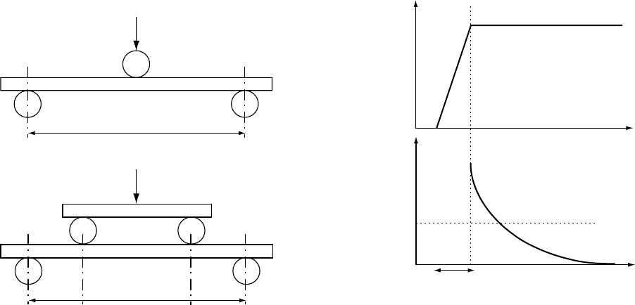
24.3.4 Flexure and Bending
We already mentioned that the machine shown in Fig.
24.4 serves also for bending. Most popular are two kinds, 3
point and 4 point, shown in Fig. 24.7, and described in
standards D 790, D 790 M (¼metric) and ISO 178. There
are also less used but more specific standards: ASTM D 747
for apparent bending modulus of plastics by means of a
cantilever beam and D 648 for deflection temperature of
plastics under flexural load.
For brittle materials, flexure testing is believed to yield
more reliable strength, modulus, and other data than the
tensile method, this primarily by reducing the pronounced
effects of misalignment in tension. For sheet materials (ex-
cept laminated thermosets, high-strength reinforced com-
posites) the dimensions of the specimens depend on
whether tested flatwise or edgewise; the thickness of the
sheet is the depth, or width, respectively. The depth shall not
exceed the width in the latter case. ASTM standards specify
also that, for sheets less than 1.5 mm in thickness, a speci-
men 50 mm long by 10 mm wide shall be tested flatwise on
a 25 mm support span. Molding materials shall be 80 by 10
by 4 mm tested flatwise on a 64 mm support span. Special
rules apply to laminated thermosets and highly anisotropic
composites, which shall be tested with a larger span-to-
thickness ratio (up to 60:1). Anisotropic materials require
four different specimens, tested edgewise and flatwise, and
cut in lengthwise and crosswise directions.
24.3.5 Stress Relaxation
Stress relaxation is typically determined in the uniaxial
mode in a specimen or part kept at constant deformation.
This pertains to parts in service such as fasteners, seals, or
screws. An example of results of such a test are shown in
Fig. 24.8. The relaxing stress could conceivably fall to zero
(curve a in the bottom part of Fig. 24.8) but in practice the
behavior displayed as curve b is observed, so that a certain
level of internal stress s
i
is established.
The concept of internal stress is very useful for bringing
out common features of stress relaxation behavior of differ-
ent kinds of materials. Instead of plotting stress vs. time t, let
us plot (s s
i
)=(s
0
s
i
) ¼ s
i
=s
0
vs: t. Here s
0
pertains
to the time of strain imposition. Such a plot was proposed
by Kuba
´
t already in 1965 [52]. An example is shown in
Fig. 24.9. We see that curves for ostensibly very different
materials have similar shapes. A large central part of each
curve has almost the same slope s as the other curves, so
that
s ¼ ( ds=dlnt)
max
¼ (0:1 0:01)(s
0
s
i
): (24:34)
To explain the situation displayed in Fig. 24.8, Kuba
´
t has
proposed a cooperative theory of stress relaxation [53,54].
He assumed that single units (metal atoms, polymer chain
segments) do not relax individually but clusters of such units
relax together. Thus, the Kuba
´
t theory is quite general an
explains the observed behavior of metals and polymers
alike. Molecular dynamics computer simulations have con-
firmed that indeed cluster relaxations prevail over individual
relaxation, and this both for metals [55] and for polymers
[56,57].
In Section 24.1.3 we have discussed among others the
time–temperature correspondence principle. An example of
application of that principle is shown in Fig. 24.10. The
results pertain to high density polyethylene (HDPE) sub-
jected to different levels of predrawing [58]. The draw ratio
is defined as
L /2
L
L /4 L /4
FIGURE 24.7. 3-point and 4-point loading modes in bending.
Strain
Stress
Time
Time
a
b
s
0
s
∞
t
0
FIGURE 24.8. Stress relaxation represented by strain vs.
time and stress vs. time curves. Explanation in text.
432 / CHAPTER 24
l ¼ « þ 1, (24:35)
where « is the engineering strain defined by Eq. (24.32). The
curves in Fig. 24.10 have the same shape as those in Fig.
24.9. The final horizontal parts are fairly long in Fig. 24.10,
a consequence of prediction over 16 decades of time. The
necessary shift factor values have been calculated from
ln a
T
¼ 1=(a þcl) þB=(
~
vv 1): (24:36)
Equation (24.36) reduces to Eq. (24.13) for l ¼ 1. Equation
(24.7) has been also used along with a representation of T
as a quadratic function of l. We see that indeed predict
of long-term behavior from short-term tests can be accom-
plished.
24.3.6 Creep
Creep denotes the time-dependent elongation of a speci-
men or part subjected to a constant stress. Normally, the
deformation range is relatively limited; the stress provided
by a dead-weight can thus be considered as fairly constant
and the change in the cross-section during the process
neglected. Such a loading mode emulates the loading situ-
ations normally encountered in engineering practice. The
pertinent standards include ASTM D 2990.
Figure 24.11 shows a schematic picture of a creep curve
plotted as strain vs. time. There is an initial elastic deform-
ation which at higher stress levels may also include a plastic
component. This is followed by the primary creep stage
characterized by a decreasing creep rate—stabilizing at a
level corresponding to the secondary or stationary creep
stage. In the end phase of the process, called tertiary creep,
the rate becomes higher again, eventually resulting in creep
rupture. It is to be noted that long-term failure may occur at
significantly lower stresses than those determined in normal
tensile testing. The logarithm of the time to rupture is often
found to decrease linearly with the applied load.
Primary (transient) creep can be considered as a consoli-
dation process during which the structure of the material
adjusts itself to the following steady-state creep stage. In
some instances, like in cross-linked elastomers at low
stresses, the steady state is absent, with the creep rate de-
creasing to zero, and the total creep strain remaining constant.
In this case, primary creep is a delayed response of the
material to the applied stress. At higher stress levels, chain
scission, oxidation effects etc. may influence this simple
behavior.
1
12 3456 7
0.2
0.4
0.6
s ∗/s ∗
0.8
1.0
10 10
2
10
3
Time (s)
10
4
10
5
0
FIGURE 24.9. Stress relaxation curves—as explained in the
text—for polyisoprene (natural rubber, 1), oriented low density
polyethylene (LDPE) with the draw ratio l ¼ 1.8 (curve 2),
indium (3), unoriented LDPE (4), cadmium (5), polyisobuty-
lene (6), and lead (7).
−8
0.00
0.05
0.10
0.15
2
1
3
s /(10
3
Jcm
−3
)
0.20
0.25
−6 −4 −4
02
log t /a
T
46810
FIGURE 24.10. Master stress relaxation curves for HDPE at
the reference temperature T ¼ 313.2 K (¼ 40 8C), the con-
stant tensile strain « ¼ 0:025 and at different values of the
draw ratio: l ¼ 12:2 in the top (1) curve; l ¼ 5:5 in the middle
(2) curve; and the material without predeformation (l ¼ 1)
in the bottom (3) curve. The symbols pertaining to the
experiment temperatures are the same in all three
curves:
&
for 50 8C;
&
for 30 8C;
~
for 10 8C;
~
for
0 8C;
*
for þ 20 8C;
*
for þ 40 8C; ^ for þ 60 8C; ^ for þ 80
8C; and for þ 100 8C. The vertical coordinate is the tensile
stress s, the horizontal is log t=a
T
; after [58].
A
B
C
Time
Strain
D
FIGURE 24.11. A schematic of a creep curve. A ¼ instant-
aneous initial deformation which may contain a plastic com-
ponent; B ¼ primary, C ¼ secondary and D ¼ tertiary creep
stage.
MECHANICAL PROPERTIES / 433
During the steady-state stage the material flows in a
viscous (plastic) manner. In some instances, this stage may
not be clearly discernible, constituting only a transition
between the primary and tertiary portions of the creep
curve. It may be noted that the acceleration of the creep
rate in the latter part is not due entirely to a decrease in the
cross-section of the specimen and thus to an increase in
the stress level in tests where the specimen is loaded with
a dead-weight.
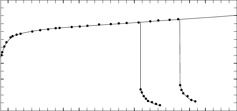
We have already mentioned creep recovery. An example
including the recovery stage is shown in Fig. 24.12.
We observe that the recovery curve is almost a mirror
image of the primary creep stage.
In Section 24.1 we have defined ways of prediction of
long-term behavior from short-term tests. Let us now pro-
vide more examples of application of these concepts. Creep
and stress relaxation have been determined for PET/
0.6PHB, where PET is the poly(ethylene terephthalate),
PHB, the p-hydroxybenzoic acid, and 0.6 is the mole frac-
tion of the latter in the copolymer [58]. PET/0.6PHB is a
polymer liquid crystal, see chapter 41 on PLCs in this Hand-
book. In temperature ranges of interest it forms 4 coexisting
phases [60]. Conventional wisdom said that prediction
methods work only for so-called rheologically simple ma-
terials, practically for one-phase polymers. Therefore, we
have decided to apply as severe a test as possible to our
prediction methods and a multiphase PLC is a good choice.
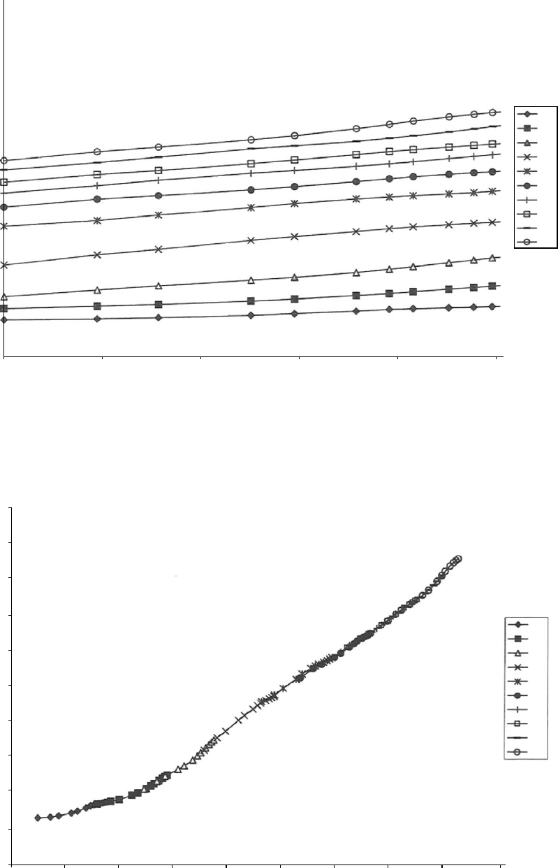
In Fig. 24.13 we show several isotherms of tensile creep
compliance (see Eq. (24.9)) for PET/0.6PHB [58]. In Fig.
24.14 we show a master curve for T
ref
¼ 62
C (the glass
transition temperature of PET, the nonliquid crystalline com-
ponent of the PLC) based on the curves from Fig. 24.13. We
see a successful prediction over 16 decades of time.
Important here of course is whether the shift factor a
T
values calculated from Eq. (24.13) agree with the experi-
mental ones. These results are displayed in Fig. 24.15. The
continuous line is calculated from our Eq. (24.13). The
dotted line is from an equation proposed in 1955 by Wil-
liams, Landel, and Ferry (WLF) [27], a pioneering a
T
(T)
formula at that time. We see that the WLF equation works
well in a certain temperature range—this seems the reason it
is still in use—but fails miserably outside of that range.
Nobody else but Ferry [1] stated that range of application
of WLF amounts to 50 K or so, not more. If one makes a
primitive and unfounded assumption in our Eq. (24.13), one
gets from it the WLF equation as a special case [6]. The
problem is when people use the WLF equation blindly in
wide temperature ranges, obtain bad results, and draw a
false conclusion that the time—temperature correspondence
principle does not work.
As already mentioned, stress relaxation was also deter-
mined for PET/0.6PHB [59]. We do not present the results
here, although also in this case one obtains a master curve
which covers 16 decades of time. Important, however, is the
comparison of a
T
(T) values from creep and stress relaxation.
This is made in Fig. 24.16. The continuous line is again
obtained from Eq. (24.13). We see that the a
T
values
obtained from these two kinds of experiments practically
coincide. Thus, Eq. (24.13) serves to predict a true material
property rather than a property related to just one kinds of
experiments.
The time—stress correspondence principle as embodied
by Eq. (24.14) has also been used successfully [61]. We do
not include such results for brevity. One could argue that the
use of equations discussed in Section 24.1 requires fairly
large amounts of experimentation. This impression might be
Time in (min)
Deformation mm
0 4 8 12 16 20 24 28 32 36 40 44 48 52 56 60
2.8
2.4
2.0
1.6
1.2
0.8
0.4
0
FIGURE 24.12. Creep and creep recovery of an oriented polypropylene monofilament with 0.35 mm in radius at 60.7 8C and
stress level s ¼ 36 J cm
3
unloaded at 35.5 and 45.5 min. Deformation in mm relates to a specimen length l
0
¼ 100 mm.
434 / CHAPTER 24
−1.50
−2.00
−2.50
−3.00
log [D
/(J cm
−3
)]
−3.50
−4.00
1.00 1.50
2.00
2.50
log (t/s)
3.00
3.50
20
40
50
60
70
80
90
100
110
120
FIGURE 24.13. Experimental tensile creep compliance for PET/0.6PHB in logarithmic coordinates at 20 8 C (the bottom curve)
and other temperatures indicated in the insert; after [59].
0.00 2.00 4.00 6.00 8.00
10.00
log (t/s)
12.00
14.00
16.00
18.00
−2.00
−
2.20
−
2.40
−
2.60
−
2.80
−
3.00
−3.20
−
3.40
−3.60
−
3.80
−4.00
log [D
/(J cm
−3
)]
20
40
50
60
70
80
90
100
110
120
FIGURE 24.14. Tensile creep compliance for PET/0.6PHB in logarithmic coordinates as the master curve for 62 8C; after [59].
MECHANICAL PROPERTIES / 435

confirmed for instance by our Fig. 24.13 which contains 10
isotherms. Therefore, methods of prediction of long-term
behavior from short-term tests based on our Eqs. (24.12)–
(24.14) have been developed [62, 63] such that one uses two
or three experimental isotherms or results for two or three
stress levels. Again, we are not going to discuss these results
here for brevity.
24.4 IMPACT BEHAVIOR
24.4.1 Rates of Force Application
We have noted in Subsection 24.2.5 that a measure of
CRC has to be defined for each specific problem. Imagine a
slow-loading process, such as a part (an early stage) of
quasistatic loading by compression. Then U
CRC
featured in
Eq. (24.2) might be relatively low; as a consequence U
r
will
be low too, but still U
r
> U
0
, and the material or component
will ‘‘survive an attack’’. However, if the loading occurs at a
fast rate, the same external energy U
0
will exceed U
r
be-
cause relaxational processes take time, and fracture will
occur. We shall now consider impact testing with this situ-
ation in mind.
24.4.2 Impact Testing
The most frequently applied impact tests are shown in
Fig. 24.17 A and B. A pendulum (shown as a filled arrow)
falls from a certain height; the loss in the potential energy of
the pendulum is assumed equal (with a correction for losses
such as friction) to the energy U
0
absorbed by the specimen;
see Eq. (24.1). The Charpy test is described by the ASTM D
256 standard method B, the lzod test by the same standard
method A. We see (Fig. 24.17 A) that in the Charpy test
there is a symmetry with respect to the center of the speci-
men. By contrast, in the lzod test (Fig. 24.17 B) the bottom
half of the specimen remains ‘‘untouched’’ while the top
part is broken off. We—and more and more laboratories
around the world—perform now both tests with a sensor
installed on the pendulum and connected to a computer.
Thus, not only a single value of the energy but a whole
curve is obtained. For convenience single values of impact
strength (IS) for a number of polymers are listed in Tables at
the end of this chapter.
There is also a combination of tension with impact shown
schematically in Fig. 24.17 C. This test is also symmetric
with respect to the center, just as the Charpy procedure.
24.4.3 Impact Transition Temperature:
Determination and Prediction
Traditionally—and that started with metals—one distin-
guishes two types of mechanical behavior of polymers:
brittle and ductile. It will be clear to us after discussion of
the free volume concept in Subsection 24.1.3 that brittle
behavior will dominate at low temperatures when the free
0
0
−5
5
10
log (a
T
)
15
−10
20 40 60 80
T /°C
100 120 140
FIGURE 24.15. The temperature shift factor a
T
(T ) for PET/
0.6PHB for 62 8C. Circles are experimental values, the dotted
line from the WLF equation and the continuous line from Eq.
(24.13) in conjunction with Eq. (24.7); after [59].
5
0
−5
−10
In (a
T
)
−15
−20
−25
−30
−35
20 40 60 80
T /°C
100 120 140
FIGURE 24.16. Experimental shift factors a
T
(T ) from creep
(full circles) and from stress relaxation (empty circles). The
continuous line is from Eq. (24.13) in conjunction with Eq.
(24.7); after [59].
Radius
r
a
w
(A) (B) (C)
FIGURE 24.17. Schematics of impact tests showing geom-
etry, loading mechanisms, and clamping modes.
436 / CHAPTER 24
volume is low. Therefore, there is a transition temperature
T
l
above which the material will be ductile. We shall
discuss the CRC connections and a way to predict T
l
in the
next Subsection. Now we shall define a procedure of ex-
perimental determination of T
l
. It should be noted immedi-
ately that the index I refers to impact; determination of
brittle-to-ductile transition by loading at a rate slower
than impact will result in finding not a single temperature,
but a temperature range; the range might be as large as
10 K [64].
In view of this, we define T
l
as the temperature at which
the response of the material changes from brittle to ductile
under high-impact conditions. The Charpy test described
above can be used to achieve those conditions [6]. As
discussed in Subsection 24.2.5, two specimens are hardly
ever identical. At T
l
we have, therefore, 50% failing in the
brittle way and the other half in the ductile way.
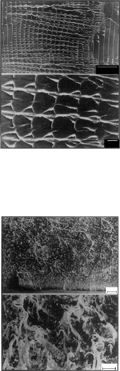
The difference between the two kinds of failure are easily
visible when one compares fracture surfaces, macroscopic-
ally as well as in micrographs obtained by scanning electron
microscopy (SEM). Macroscopically, the fracture surface of
a brittle failure appears smooth. SEM micrographs show in
this case a ‘‘flaky’’ surface. By contrast, ductile failure is
characterized by ‘‘hills and valleys’’ with deformed strands
coming out from the surface, as well as holes in the surface
left by strands which at break time have ‘‘joined’’ the other
surface. Examples of the two types of micrographs are
shown, respectively, in Figs. 24.18 and 24.19. There is a
whole book by Michler [65] on polymer micromechanics
which contains many instructive SEM micrographs of frac-
ture surfaces as well as crazes, shear yielding, and also
combinations such as crazes crossing shear bands.
Using the concepts discussed in Sections 24.1 and 24.2,
the following equation [6] was derived:
K
t
¼ F e
B=(v
l
1)
(24:37)
here K
t
is the stress concentration factor as defined by
Eq. (24.15); B is the Doolittle constant from Eq. (24.8);
and the reduced volume
~
vv
l
is that at the impact-transition
temperature T
l
. Thus, we have an implicit formula for T
l
which can be related to
~
vv
l
by an equation of state such as
Eq. (24.6) or (24.7); there is a T
l
value corresponding to each
stress concentration factor.
Equation (24.37) was tested for LDPE for which suffi-
cient data were available. The results are shown in Fig.
24.20. We see that the equation is obeyed within the limits
of the experimental accuracy. Thus, two pairs of T
l
and K
t
values are sufficient for the calculation of the parameters
F and B and for subsequent prediction of the entire diagram.
24.4.4 Prediction of Volumetric Properties from
Impact Data
We have used above free volume to explain mechanical
properties. Since we have at our disposal quantitative rela-
tionships which work well, it was tempting to see whether
the relationships can be used also in the opposite direction:
going from mechanical properties toward volumetric ones.
Thus, Eq. (24.37) was used in this opposite direction [66]:
100µm
10µm
FIGURE 24.18. SEMicrograph of a brittle fracture surface;
after [65].
100µm
5µm
FIGURE 24.19. SEMicrograph of a ductile fracture surface;
after [65].
MECHANICAL PROPERTIES / 437
specific volume v was obtained for the first time from
mechanical parameters—the impact transition data—via
an equation of state. The result was prediction of v over a
temperature range of 100 K. The average difference be-
tween calculated and experimental specific volume values
was only 0.092%. This constitutes one more confirmation—
and of a different type—of the physical significance of the
CRC concept and of the relations based on that concept.
24.5 VISCOELASTICITY AND DYNAMIC
MECHANICAL TESTING
24.5.1 Objectives and Definitions
As noted in Subsection 24.1.2, viscoelasticity of polymers
represents a combination of elastic and viscous flow mater-
ial responses. Dynamic mechanical analysis (DMA, also
called dynamic mechanical thermal analysis, DMTA) en-
ables simultaneous study of both elastic (symbol ’) and
viscous flow (symbol ’’) types of behavior. One determines
the response of a specimen to periodic deformations or
stresses. Normally, the specimen is loaded in a sinusoidal
fashion in shear, tension, flexion, or torsion. If, say, the
experiment is performed in tension, one determines the elas-
tic tensile modulus E’ called storage modulus and the corre-
sponding viscous flow quantity E’’ called the loss modulus.
Diagrams showing the temperature or frequency depend-
ence of storage and loss modulae can be used to locate the
thermal transition regions such as the glass transition—
although other methods such as differential scanning calor-
imetry (DSC) can be used for that purpose as well. At the
same time, the dynamic mechanical methods constitute the
primary technique for the study of dissipation mechanisms,
and thus of CRC. Clearly DMA data are of importance in
designing products to be used in, for instance, vibration
isolation, where the mechanical damping properties are
used to convert mechanical vibrations into heat. Methods
of this type are also highly useful in studies of phase separ-
ation in multicomponent systems, effects of fillers and other
additives, different processing variables, degree of crystal-
linity, molecular orientation, internal stresses, etc.
Consider a material subjected to an oscillating load of
small amplitude that is in the linear viscoelastic range. The
angular frequency of the sinusoidal oscillation is v. A si-
nusoidal stress s will produce a sinusoidal strain «, and vice
versa. However, because of the viscous component of the
deformation, there will be a phase shift between stress
and strain. The pertinent quantities can be represented as
follows:
« ¼ «
0
sin vt (24:38)
s ¼ s
0
sin (vt þd)
¼ s
0
sin vt cos d þ s
0
cos vt sin d: (24:39)
Here s
0
and «
0
denote, respectively, the amplitudes of stress
and strain, t the time, and d the phase shift between stress
and strain. An illustration is provided in Fig. 24.21.
As already mentioned, the description of the response of a
viscoelastic material to a sinusoidal tensile strain requires
the introduction of two modulae; they are defined as
E
0
¼
s
0
«
0
cos d ¼ E
d
cos d (24:40)
E
00
¼
s
0
«
0
sin d ¼ E
d
sin d, (24:41)
E
d
is named the absolute value of the dynamic modulus.
Obviously,
E
d
¼ [(E
0
)
2
þ (E
00
)
2
]
1=2
: (24:42)
The introduction of E’ and E’’ enables us to write Eq. (24.39)
as
s ¼ «
0
E
0
sin vt þ«
0
E
00
cos vt: (24:43)
160
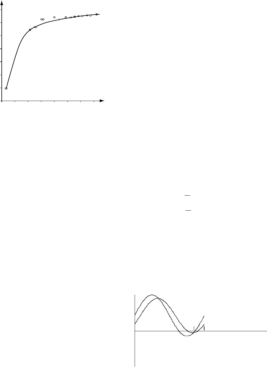
0 4 8 1216202428
K
t
180
200
220
240
260
280
300
T
I
FIGURE 24.20. Relation between the stress concentration
factor K
t
and the impact transition temperature T
l
in K for
LDPE. Circles represent experimental values obtained by
the Charpy method and crosses those calculated from Eq.
(24.37).
s s
0
sin(wt + d )
e e
0
sin(wt)
d
FIGURE 24.21. The phase lag of the strain « resulting from
an applied sinusoidal stress s.
438 / CHAPTER 24