Middleton W.M. (ed.) Reference Data for Engineers: Radio, Electronics, Computer and Communications
Подождите немного. Документ загружается.

49-1
4
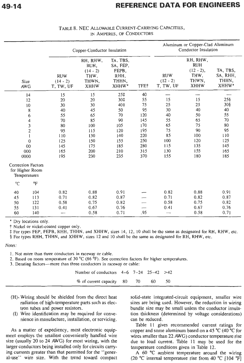
TABLE
8.
NEC ALLOWABLE CURRENT-CARRYING CAPACITIES,
IN
AMPERES,
OF
CONDUCTORS
Aluminum
or
Copper-Clad Aluminum
Copper-Conductor Insulation
Conductor Insulation
RH, RHW, TA, TBS,
RH, RHW,
RUH
,
SA, FEP,
RUH
(14
-
2)
FEPB
,
(12
-
2),
TA, TBS,
RUW THW, RHH, RUW THW, SA,RHH,
Size
(14
-
2)
THWN, THHN,
(12
-
2)
THWN, THHN
,
AWG T,TW,UF XHHW XHHW* TFET T,TW,UF XHHW XHHW*
- -
-
40
14 15 15
12 20 20
10
30 30 40f 75
30$ 15 15 2%
25 25 308
25$ 55
8 40
45
50
95 30 40 40
6 55
65 70 120 40
50 55
4 70
85 90 145 55
65 70
3 80
100 105 170 65
75 80
2 95
115 120 195 75
90 95
1 110
130 140 220 85
100 110
0
125
150 155 250
100
120
125
00
145 175 185 280
115 135 145
000
165 200 210 315 130 155 165
0000
195 230 235 370 155 180 185
Correction Factors
for Higher Room
Temperatures
"C
OF
40 104 0.82
0.88 0.91
-
0.82
0.88 0.91
45 113
0.71
0.82 0.87
-
0.71 0.82
0.87
50
122 0.58
0.75 0.82
-
0.58
0.75 0.82
55 131 0.41
0.67 0.76
-
0.41
0.67 0.76
60 140
-
0.58
0.71 .95
-
0.58 0.71
*
Dry locations only.
t
Nickel
or
nickel-coated copper only.
$
For types FEP,
FEPB,
RHH, THHN, and XHHW, sizes
14, 12,
10 shall be the same
as
designated
for
RH, RHW, etc.
0
For types RHH, THHN, and XHHW, sizes
12
and
10
shall be the same
as
designated
for
RH, RHW, etc.
Notes:
1.
Not more than three conductors in raceway
or
cable.
2.
Based on room temperature
of
30
OC
(86
OF).
See correction factors for higher temperatures.
3.
Derating factors-more than three conductors in raceway
or
cable:
Number
of
conductors
4-6 7-24 25-42 >42
%
of
current capacity
80 70 60 50
(H), Wiring should be shielded from the direct heat
radiation of high-temperature parts such as elec-
tron tubes and power resistors.
(I)
Wire identification may be required for conve-
nience in manufacture, installation, or servicing.
As
a matter of expediency, most electronic equip-
ment employs the smallest conveniently handled wire
size (usually 20 to 24
AWG)
for most wiring, with the
larger conductors being installed only for circuits carry-
ing currents greater than that permitted for the "gener-
al-use" wire size. With the trend toward compact
solid-state integrated-circuit equipment, smaller wire
sizes are being used. However, the reduction in wiring
bundle size may be small unless the conductor insula-
tion thickness (determined by voltage considerations)
can be reduced.
Table 11 gives recommended current ratings for
copper and some aluminum based on a
45
"C
(40 "C for
wires smaller than 22
AWG)
conductor temperature rise
due to load current. Table
11
may be used for the
temperature conditions given in Table 12.
A
60
"C
ambient temperature around the wiring
(20
"C
internal temperature rise from
40
"C
[IO4
OF]
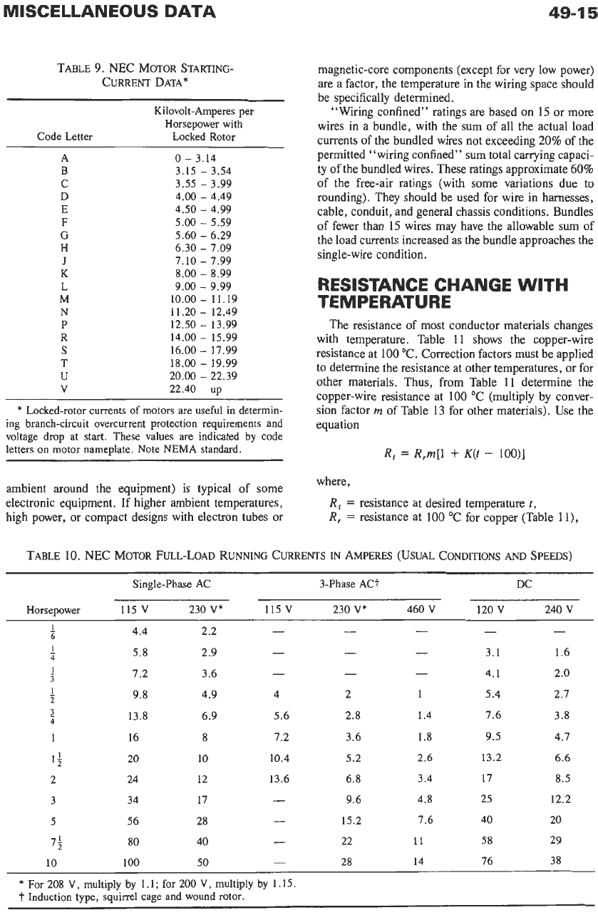
TABLE
9.
NEC MOTOR STARTING-
CURRENT DATA*
Kilovolt-Amperes per
Horsepower
with
Code Letter Locked Rotor
~~~
A
0
-
3.14
B
3.15
-
3.54
C
3.55
-
3.99
D
4.00
-
4.49
E
4.50
-
4.99
F
5.00
-
5.59
G
5.60
-
6.29
H
6.30
-
7.09
J
7.10
-
1.99
K
8.00
-
8.99
L
9.00
-
9.99
M
10.00
-
11.19
N
11.20
-
12.49
P
12.50
-
13.99
R
14.00
-
15.99
S
16.00
-
17.99
T
18.00
-
19.99
U
20.00
-
22.39
V
22.40
up
*
Locked-rotor currents of motors are
useful
in
determin-
ing branch-circuit overcurrent protection requirements and
voltage drop
at
start. These values are indicated
by
code
letters
on
motor nameplate.
Note
NEMA standard.
ambient around the equipment) is typical of some
electronic equipment. If higher ambient temperatures,
high power, or compact designs with electron tubes or
magnetic-core components (except for very low power)
are a factor, the temperature in the wiring space should
be specifically determined.
“Wiring confined” ratings are based
on
15
or more
wires in a bundle, with the sum of all the actual load
currents of the bundled wires
not
exceeding
20%
of the
permitted “wiring confined” sum total carrying capaci-
ty of the bundled wires. These ratings approximate
60%
of the free-air ratings (with some variations due to
rounding). They should be used for wire in harnesses,
cable, conduit, and general chassis conditions. Bundles
of
fewer than
15
wires may have the allowable sum of
the load currents increased as the bundle approaches the
single-wire condition.
RESISTANCE CHANGE WITH
TEMPERATURE
The resistance of most conductor materials changes
with temperature. Table
11
shows the copper-wire
resistance at
100
“C. Correction factors must be applied
to determine the resistance at other temperatures, or for
other materials. Thus, from Table 11 determine the
copper-wire resistance at 100 “C (multiply by conver-
sion factor
m
of
Table 13 for other materials). Use the
equation
R,
=
R,m[l
+
K(t
-
loo)]
where,
R,
=
resistance at desired temperature
t,
R,
=
resistance at 100 “C for copper (Table ll),
TABLE 10. NEC MOTOR FULL-LOAD RUNNING CURRENTS
IN
AMPERES (USUAL CONDITIONS
AND
SPEEDS)
Single-phase AC 3-Phase ACT DC
Horsepower
115
V
230
V*
115
V
230
V*
460
V
120
v
240
V
I
1
-
-
-
- - -
6
4.4 2.2
4
3.1 1.6
3
4.1 2.0
-
-
-
-
5.8 2.9
7.2 3.6
1
9.8 4.9 4 2
1
5.4 2.7
1
13.8 6.9 5.6 2.8 1.4 7.6 3.8
2
1 16
8
7.2
3.6
1.8 9.5
4.7
1;
20
10
10.4
5.2
2.6 13.2
6.6
2 24 12 13.6
6.8 3.4
17 8.5
3 34 17
-
9.6
4.8
25 12.2
5 56
28
-
15.2
7.6
40 20
1;
80
40
-
22
11 58
29
10
100
50
-
28
14 76
38
- - -
2
4
*
For
208
V, multiply by
1.1;
for
200
V,
multiply
by
1.15.
t
Induction tvoe. sauirrel
cage
and
wound
rotor.
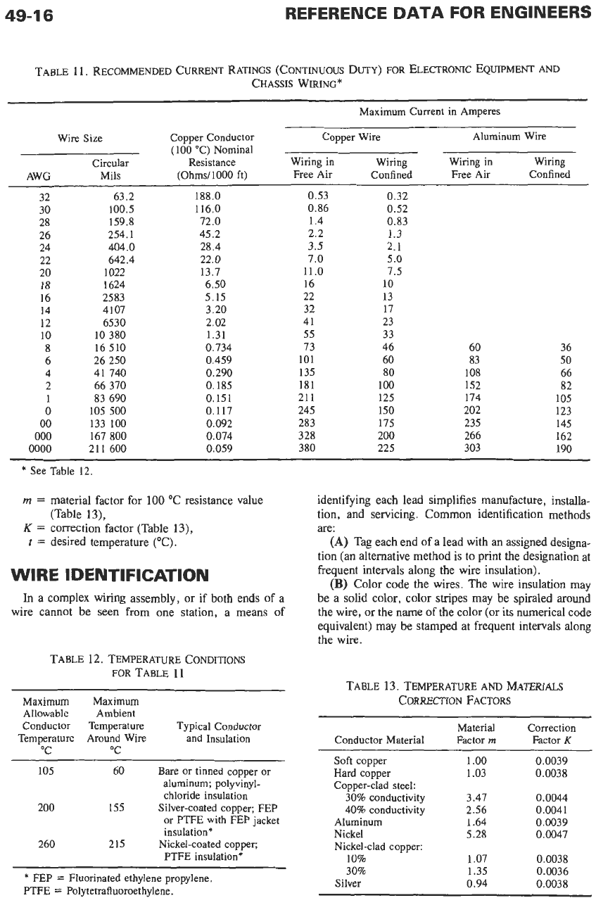
TABLE 11. RECOMMENDED CURRENT RATINGS (CONTINUOUS
DUTY)
FOR
ELECTRONIC EQUIPMENT
AND
CHASSIS WIRING*
Maximum Current in Amperes
Wire Size Copper Conductor Copper Wire Aluminum Wire
(100
"C) Nominal
Circular Resistance Wiring in Wiring Wiring in Wiring
AWG Mils
(Ohms/1000
ft) Free Air Confined Free Air Confined
32 63.2 188.0 0.53 0.32
30 100.5 116.0 0.86 0.52
28
26
24
22
20
18
16
14
12
10
8
6
4
2
1
0
00
000
0000
159.8
254.1
404.0
642.4
1022
1624
2583
4107
6530
10 380
16 510
26 250
41 740
66 370
83 690
105 500
133
100
167 800
211 600
72.0
45.2
28.4
22.0
13.7
6.50
5.15
3.20
2.02
1.31
0.734
0.459
0.290
0.185
0.151
0.117
0.092
0.074
0.059
1.4
2.2
3.5
7.0
11.0
16
22
32
41
55
73
101
135
181
21
1
245
283
328
380
0.83
1.3
2.1
5.0
7.5
10
13
17
23
33
46
60
80
100
125
150
175
200
225
60
83
108
152
174
202
235
266
303
36
50
66
82
105
123
145
162
190
*
See Table
12.
m
=
material factor for
100
"C resistance value
K
=
correction factor (Table 13),
(Table 13),
t
=
desired temperature ("C).
WIRE
IDENTIFICATION
In a complex wiring assembly, or if both ends of a
wire cannot be seen from one station. a means of
TABLE 12. TEMPERATURE CONDITIONS
FOR
TABLE 11
Maximum Maximum
Allowable Ambient
Conductor Temperature Typical Conductor
Temperature Around Wire and Insulation
"C "C
105 60
Bare
or tinned copper or
aluminum; polyvinyl-
chloride insulation
200 155
Silver-coated copper; FEP
or PTFE with FEP jacket
insulation*
PTFE insulation*
260 215
Nickel-coated copper;
*
FEP
=
Fluorinated ethylene propylene.
PTFE
=
Polytetrafluoroethylene.
identifying each lead simplifies manufacture, installa-
tion, and servicing. Common identification methods
are:
(A)
Tag each end of a lead with an assigned designa-
tion
(an
alternative method is to print the designation at
frequent intervals along the wire insulation).
(B)
Color code the wires. The wire insulation may
be a solid color, color stripes may be spiraled around
the
wire,
or the name
of
the color (or its numerical code
equivalent) may be stamped at frequent intervals along
the wire.
TABLE
13.
TEMPERATURE
AND
MATERIALS
CORRECTION
FACTORS
Material Correction
Conductor Material Factor
rn
Factor
K
Soft copper
Hard copper
Copper-clad steel:
30%
conductivity
40%
conductivity
Aluminum
Nickel
Nickel-clad copper:
10%
30%
Silver
1
.oo
1.03
3.47
2.56
1.64
5.28
1.07
1.35
0.94
0.0039
0.0038
0.0044
0.0041
0.0039
0.0047
0.0038
0.0036
0.0038
MISCELLANEOUS DATA
49-1
7
Color Coding
The commonly used colors and their numerical codes
are:
0
Black
5
Green
1
Brown
6
Blue
2
Red
7
Violet (purple)
3
Orange
8
Gray (slate)
4
Yellow
9
White
While spiral stripes can be applied
on
top of any
basic insulation color, under less favorable viewing
conditions it is difficult to distinguish some colors from
the basic insulation color. Identification may be slow
and subject
to
error. The preferred combination consists
of one or two (sometimes three) colored stripes
on
a
white basic insulation. To minimize identification er-
rors, the first stripe is made wider than the second (or
third), and some rules require that the second stripe be
of higher numerical code than the first stripe. If the
required variety of wire color codes is not great, the
preceding guides should be followed.
Table 14 gives a standard color code used to distin-
guish by function the various leads in electronic cir-
cuits.
In
manufacturing practice, it is preferred that, at any
harness breakout point, all wires of the same color code
be connected to the same terminal at that location.
When this rule and the wire color coding of Table
14
are
both applicable, additional tracers may be used to
supplement the primary coding of Table
14.
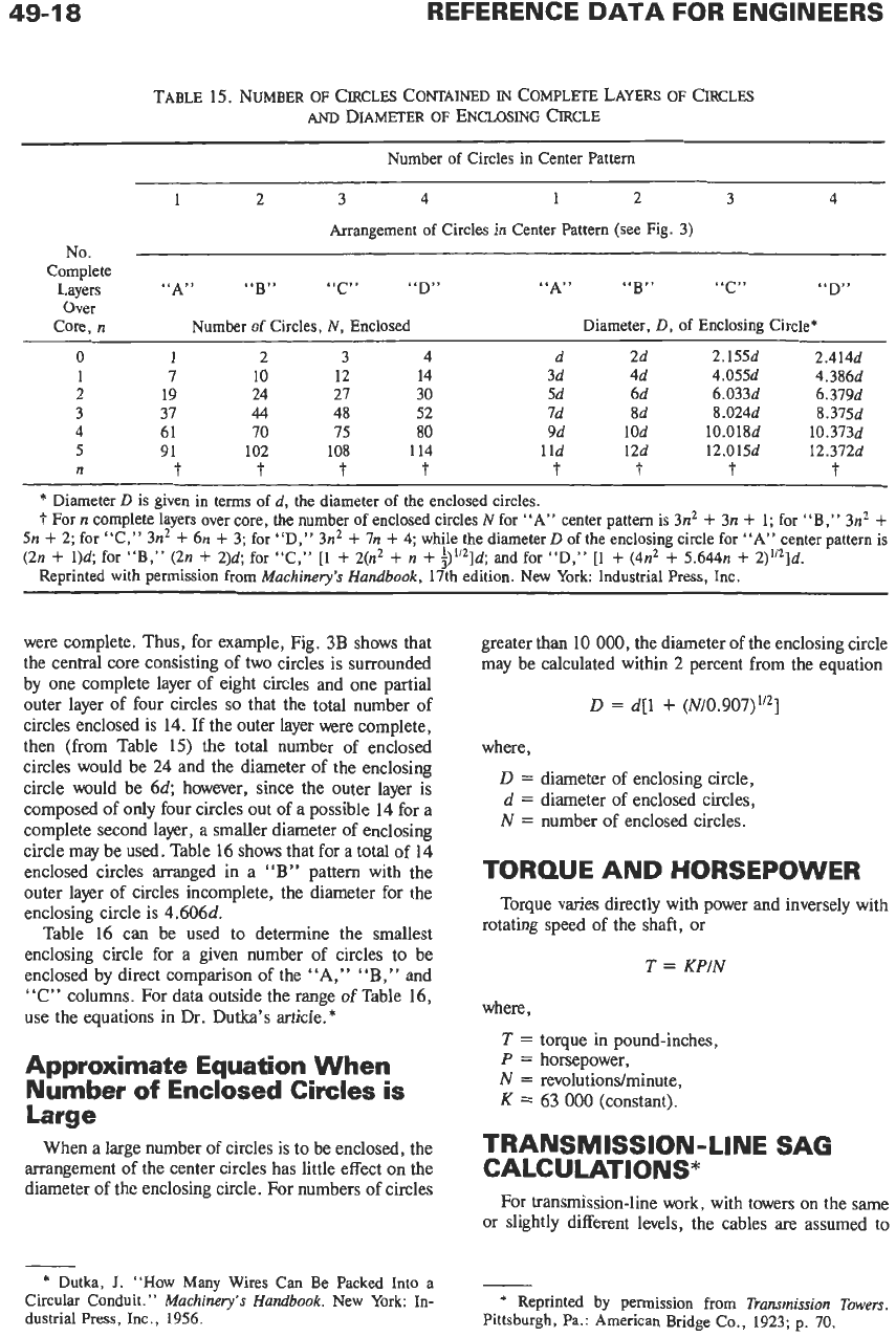
DIAMETER
OF
CIRCLE
ENCLOSING A GIVEN
NUMBER
OF
SMALLER
CIRCLES*
Four of many possible compact arrangements of
circles within a circle are shown in Fig.
3.
To determine
the diameter of the smallest enclosing circle for a
particular number of enclosed circles all
of
the same
size, three factors that influence the size of the enclos-
ing circle should be considered, as follows.
Arrangement
of
Center or
Core Circles
The four most common arrangements of center or
core circles
are
shown in cross section in Fig.
3.
It
may
seem that Fig.
3A
would require the smallest enclosing
circle for a given number of enclosed circles, but this is
not always the case since the most compact arrangement
will depend in part
on
the number of circles to be
enclosed.
TABLE 14.
COLORS
FOR
WIRE
IDENTIFICATION
BY
FUNCTION
Identifi-
Function Color cation
No.
Grounds, grounded Black
0
Power supply B
+
Red
2
Screen grids Orange 3
Cathodes and transistor Yellow
4
Control grids and tran- Green
5
elements
Heaters or filaments Brown
1
emitters*
t
sistor basest
sistor collectors*t
Anodes (plates) and tran- Blue
6
Power supply, negative
(-)
Violet (purple)
7
Ac power lines Gray (slate)
8
*
Applies to diodes, semiconductor elements, photoelec-
tric cells, mercury-arc rectifiers, and other elements with
operation similar to vacuum tubes and transistors.
t
Applies
to
all types
of
gas tubes with operation similar to
vacuum tubes.
Diameter
of
Enclosing Circle
When Outer Layer
of
Circles
Is
Complete
Successive, complete “layers” of circles may be
placed around each
of
the central cores of 1,
2,
3,
or
4
circles. The number of circles contained in arrange-
ments of complete “layers” around a central core of
circles, as well as the diameter of the enclosing circle,
may be obtained from Table
15.
Thus, for example,
Fig.
3A
has a total of
18
circles arranged in two
complete “layers” around a central core consisting of
one circle; this agrees with the data shown in the left
half of Table
15
for
n
=
2.
To determine the diameter of the enclosing circle, the
data in the right half of Table
15
are
used. Thus, for
n
=
2
and an
“A”
pattern, diameter
D
is
5
times the
diameter,
d,
of the enclosed circles.
Diameter
of
Enclosing Circle
When Outer Layer
of
Circles
Is
Not Complete
In
most cases, it
is
possible to reduce the size of the
enclosing circle
from
that required
if
the outer layer
A
B
C
D
-
*
Dutka,
J.
“How Many Wires Can Be Packed Into a
Circular Conduit.
”
Machinery’s Handbook.
New York In-
dustrial Press, Inc.,
1956.
Fig.
3.
Arrangements
of
circles within a circle.
(Reprinted
with permission from
Machinery’s Handbook,
17th Edition,
Industrial Press,
Inc.,
New York.)
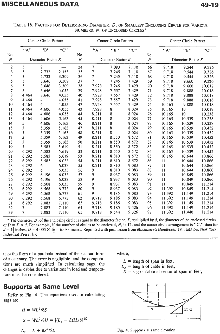
49-1
8
TABLE
15.
NUMBER
OF
CIRCLES CONTAINED
IN
COMPLETE
LAYERS
OF
CIRCLES
AND
DIAMETER
OF
ENCLOSING
CIRCLE
Number of Circles
in
Center Pattern
1
2 3 4
1
2 3 4
Arrangement
of
Circles
in
Center Pattern (see Fig.
3)
No.
Complete
Over
Core,
n
Layers
“A”
“B”
“C”
“D”
“A”
“B”
“C” “D”
Number of Circles,
N,
Enclosed
Diameter,
D,
of
Enclosing Circle*
0
1
2 3 4 d
2d
2.155d 2.414d
1
7 10 12 14 3d 4d 4.055d 4.386d
2 19 24 21 30 5d
6d
6.033d 6.379d
3 37
44
48 52 7d
8d 8.024d
8.375d
4 61 70 75
80
9d
1
Od
10.018d 10.373d
5
91 102 108 114
1
Id
12d
12.015d 12.372d
n
t
t
t
t
t
t
t
t
*
Diameter
D
is given in terms
of
d,
the
diameter
of
the enclosed circles.
t
For
n
complete layers over core, the number of enclosed circles
N
for
“A”
center pattern is
3n2
+
3n
+
1;
for “B,”
3n2
+
5n
+
2;
for “C,”
3n2
+
6n
+
3;
for “D,”
3nZ
+
7n
+
4;
while the diameter
D
of the enclosing circle for
“A”
center pattern is
(2n
+
1)d;
for “B,”
(2n
+
2)d;
for “C,”
[l
+
2(nz
+
n
+
$”‘Id;
and for “D,”
[l
+
(4n2
+
5.644n
+
2)”2]d.
Reprinted with permission from
Machinery’s Handbook,
17th
edition. New York: Industrial Press, Inc.
were complete. Thus, for example, Fig.
3B
shows that
the central core consisting of two circles is surrounded
by one complete layer of eight circles and one partial
outer layer of four circles
so
that the total number
of
circles enclosed is
14.
If the outer layer were complete,
then (from Table
15)
the total number of enclosed
circles would be
24
and the diameter of the enclosing
circle would be
64
however, since the outer layer is
composed of only four circles out of a possible
14
for a
complete second layer, a smaller diameter of enclosing
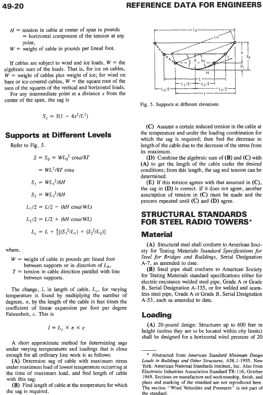
circle may be used. Table
16
shows that for a total of
14
enclosed circles arranged in a
“B”
pattern with the
outer layer of circles incomplete, the diameter for the
enclosing circle is
4.606d.
Table
16
can be used to determine the smallest
enclosing circle for a given number
of
circles to be
enclosed by direct comparison of the
“A,”
“B,”
and
“C”
columns. For data outside the range of Table
16,
use the equations in Dr.
Dutka’s
article.*
Approximate Equation When
Number
of
Enclosed Circles
is
Large
When a large number of circles
is
to be enclosed, the
arrangement of the center circles has little effect on the
diameter
of
the enclosing circle. For numbers
of
circles
greater than
10
000,
the diameter of the enclosing circle
may be calculated within
2
percent from the equation
D
=
d[l
+
(N/0.907)”2]
where,
D
=
diameter of enclosing circle,
d
=
diameter of enclosed circles,
N
=
number of enclosed circles.
TORQUE AND HORSEPOWER
Torque varies directly with power and inversely with
rotating speed of the shaft, or
T
=
KPIN
where,
T
=
torque in pound-inches,
P
=
horsepower,
N
=
revolutionshninute,
K
=
63
000
(constant).
TRANSMISSION-LINE
SAG
CALCULATIONS*
For transmission-line work, with towers on the same
or slightly different levels, the cables are assumed to
*
Dutka,
J.
“How
Many Wires Can Be Packed Into
a
Circular Conduit.”
Machinery’s Handbook.
New York: In-
dustrial Press, Inc.,
1956.
*
Reprinted
by
permission from
Transmission Towers.
Pittsburgh, Pa.:
American
Bridge Co.,
1923;
p.
70.
TABLE
16.
FACTORS
FOR
DETERMINING DIAMETER,
D,
OF SMALLEST
ENCLOSING
CIRCLE FOR VARIOUS
NUMBERS,
N,
OF
ENCLOSED
CIRCLES*
Center Circle Pattern
Center Circle Pattern
~~ ~~
Center Circle Pattern
“A”
“B”
“C?’
“A”
“B”
“C” “A”
“B”
“C”
No.
No.
No.
N
Diameter Factor
K
N
Diameter Factor
K
N
Diameter Factor
K
2
3
4
5
6
7
8
9
10
11
12
13
14
15
16
17
18
19
20
21
22
23
24
25
26
27
28
29
30
31
32
33
3
3
3
3
3
3
4.464
4.464
4.464
4.464
4.464
4.464
5
5
5
5
5
5
6.292
6.292
6.292
6.292
6.292
6.292
6.292
6.292
6.292
6.292
6.292
6.292
7
7
2
2.732
2.732
3.646
3.646
3.646
3.646
4
4
4.606
4.606
4.606
4.606
5.359
5.359
5.359
5.359
5.583
5.583
5.583
5.583
6
6
6.196
6.196
6.568
6.568
6.568
6.568
7.083
7.083
7.083
-
2.155
3.309
3.309
3.309
4.055
4.055
4.055
4.055
4.055
4.055
5.163
5.163
5.163
5.163
5.163
5.163
5.619
5.619
5.619
6.033
6.033
6.033
6.033
6.033
6.033
6.773
6.773
6.773
7.110
7.110
7.110
34
35
36
37
38
39
40
41
42
43
44
45
46
47
48
49
50
51
52
53
54
55
56
57
58
59
60
61
62
63
64
65
7
7
7
I
7.928
7.928
7.928
7.928
7.928
7.928
8.211
8.211
8.21 1
8.21 1
8.211
8.211
8.211
8.21
1
8.211
8.211
8.211
8.211
9
9
9
9
9
9
9.718
9.718
9.718
9.718
7.083
7.245
7.245
7.245
I.
245
7.557
7.557
7.557
7.551
8
8
8
8
8
8
8.550
8.550
8.550
8.550
8.810
8.810
8.810
8.810
8.937
8.937
8.937
8.937
9.185
9.185
9.185
9.185
9.544
7.110
7.110
7.110
7.429
7.429
7.429
7.429
7.429
1.429
8.024
8.024
8.024
8.024
8.024
8.024
8.572
8.572
8.572
8.572
8.572
8.572
9.083
9.083
9.083
9.083
9.083
9.083
9.083
9.083
9.083
9.326
9.326
66
67
68
69
70
71
72
73
74
75
76
77
78
79
80
81
82
83
84
85
86
87
88
89
90
91
92
93
94
95
96
97
9.718
9.718
9.718
9.718
9.718
9.718
9.718
9.718
10.165
10.165
10.165
10.165
10.165
10.165
10.165
10.165
10.165
10.165
10.165
10.165
11
11
11
11
11
11
11.392
11.392
11.392
11.392
11.392
11.392
9.544
9.544
9.544
9.660
9.660
9.888
9.888
9.888
9.888
10
10
10.539
10.539
10.539
10.539
10.539
10.539
10.539
10.539
10.644
10.644
10.644
10.644
10.849
10.849
10.849
10.849
11.149
11.149
11.149
11.149
11.440
9.326
9.326
9.326
9.326
10.018
10.018
10.018
10.018
10.018
10.018
10.238
10.238
10.238
10.452
10.452
10.452
10.452
10.452
10.452
10.866
10.866
10.866
10.866
10.866
10.866
11.214
11.214
11.214
11.214
11.214
11.214
11.214
*
The diameter,
D,
of the enclosing circle is equal to the diameter factor,
K,
multiplied
by
d,
the diameter of the enclosed circles,
or
D
=
K
X
d.
For example, if the number of circles to be enclosed,
N,
is
12,
and the center circle arrangement is “C,” then for
d
=
1;
inches,
D
=
4.005
X
1;
=
6.083
inches. Reprinted with permission fromMuchineryS
Handbook,
17th
Edition. New York
Industrial Press, Inc.
take the form of a parabola instead of their actual form
of a catenary. The error is negligible, and the computa-
tions are much simplified. In calculating sags, the
changes in cables due
to
variations in load and tempera-
ture must be considered.
where,
L
=
length
of
span in feet,
L,
=
length
of
cable in feet,
S
=
sag
of
cable at center
of
span in feet,
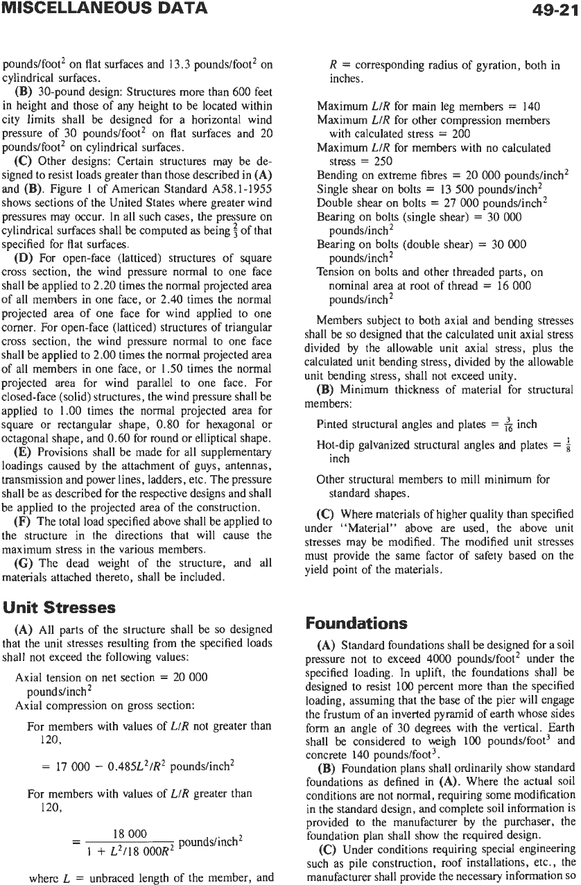
Supports
at
Same
Level
Refer to Fig.
4.
The equations used in calculating
sags are
H
=
WL2/8S
S
=
WL2/8H
=
[(L,
-
L)3L/8]”*
L,
=
L
+
8S2/3L
Fig.
4.
Supports at same elevation.
49-20
REFERENCE
DATA
FOR ENGINEERS
H
=
tension in cable at center of span in pounds
=
horizontal component
of
the tension at any
point,
H
L
W
=
weight of cable in pounds per lineal foot.
If cables are subject to wind and ice loads,
W
=
the
algebraic sum of the loads. That is, for ice on cables,
W
=
weight of cables plus weight of ice; for wind on
bare or ice-covered cables,
W
=
the square root of the
sum
of
the squares of the vertical and horizontal loads.
For any intermediate point at a distance
x
from the
center
of
the span, the sag is
Fig. 5. Supports at different elevations.
s,
=
S(1
-
421L2)
Supports at Different Levels
Refer to Fig.
5.
S
=
So
=
WL2 cosaI8T
=
WL2/8T cosa
S,
=
WLf2I8H
S2
=
WL?/8H
L1/2
=
L12
-
(hH
cosalWL)
L2/2
=
L12
+
(hH cosalWL)
L,
=
L
+
i[(S,21L,)
+
(S?/LZ)l
where,
W
=
weight of cable in pounds per lineal foot
between supports or in direction
of
Lo,
T
=
tension in cable direction parallel with line
between supports.
The change,
E,
in length of cable, L,, for varying
temperature is found by multiplying the number
of
degrees,
n,
by the length
of
the cable in feet times the
coefficient of linear expansion per foot per degree
Fahrenheit,
c.
This
is
l=L,Xnxc
A
short approximate method for determining sags
under varying temperatures and loadings that is close
enough for all ordinary line work is as follows:
(A)
Determine sag
of
cable with maximum stress
under maximum load of lowest temperature occurring at
the time
of
maximum load, and find length
of
cable
with this sag.
(B)
Find length of cable at the temperature for which
the sag is required.
(C)
Assume a certain reduced tension in the cable at
the temperature and under the loading combination for
which the sag is required; then find the decrease in
length of the cable due to the decrease
of
the stress from
its maximum.
(D)
Combine the algebraic sum of
(B)
and
(C)
with
(A)
to get the length of the cable under the desired
conditions; from this length, the sag and tension can be
determined.
(E)
If
this tension agrees with that assumed in
(C),
the sag in
(D)
is correct. If it does not agree, another
assumption
of
tension in
(C)
must be made and the
process repeated until
(C)
and
(D)
agree.
STRUCTURAL STANDARDS
FOR STEEL RADIO TOWERS*
Material
(A)
Structural steel shall conform to American Soci-
ety for Testing Materials
Standard SpeciJcations for
Steel for Bridges
and
Buildings,
Serial Designation
A-7,
as amended to date.
(B)
Steel pipe shall conform to American Society
for Testing Materials standard specifications either for
electric-resistance welded steel pipe, Grade A
or
Grade
B,
Serial Designation A-135, or for welded and seam-
less steel pipe, Grade A or Grade
B,
Serial Designation
A-53, each
as
amended to date.
Loading
(A)
20-pound design: Structures up to
600
feet in
height (unless they
are
to
be
located within city limits)
shall be designed for a horizontal wind pressure of
20
-
*
Abstracted from
American Standard Minimum Design
Loads in
Buildings
and
Other Structures,
A58.1-1955.
New
York: American National Standards Institute, Inc. Also from
Electronic Industries Association Standard TR-116, October
1949. Sections on manufacture and workmanship, finish, and
plans and marking
of
the standard are not reproduced here.
The section “Wind Velocities and Pressures’’ is not part of
the
standard.
poundslfoot’ on flat surfaces and
13.3
poundslfoot’ on
cylindrical surfaces.
(B)
30-pound design: Structures more than
600
feet
in height and those of any height to be located within
city limits shall be designed for a horizontal wind
pressure of 30 poundslfoot’ on flat surfaces and
20
poundslfoot’ on cylindrical surfaces.
(C)
Other designs: Certain structures may be de-
signed to resist loads greater than those described in
(A)
and
(B).
Figure
1
of American Standard A58.1-1955
shows sections of the United States where greater wind
pressures may occur. In all such cases, the pressure on
cylindrical surfaces shall be computed as being of that
specified for flat surfaces.
(D)
For open-face (latticed) structures
of
square
cross section, the wind pressure normal to one face
shall be applied to
2.20
times the normal projected area
of all members in one face, or
2.40
times the normal
projected area
of
one face for wind applied to one
comer. For open-face (latticed) structures of triangular
cross section, the wind pressure normal to one face
shall be applied to
2.00
times the normal projected area
of all members in one face, or
1.50
times the normal
projected area for wind parallel to one face. For
closed-face (solid) structures, the wind pressure shall be
applied to
1.00
times the normal projected area for
square or rectangular shape,
0.80
for hexagonal or
octagonal shape, and
0.60
for round or elliptical shape.
(E)
Provisions shall be made for all supplementary
loadings caused by the attachment of guys, antennas,
transmission and power lines, ladders, etc. The pressure
shall be as described for the respective designs and shall
be applied to the projected area of the construction.
(F)
The total load specified above shall be applied to
the structure in the directions that will cause the
maximum stress in the various members.
(G)
The dead weight of the structure, and all
materials attached thereto, shall be included.
Unit Stresses
(A)
All parts of the structure shall be
so
designed
that the unit stresses resulting from the specified loads
shall not exceed the following values:
Axial tension on net section
=
20
000
Axial compression on gross section:
poundslinch’
For members with values of LIR not greater than
120.
=
17
000
-
0.485L’IR‘ poundslinch’
For members with values of LIR greater than
120,
poundslinch2
-
18
000
-
1
+
L’118 OOOR
where L
=
unbraced length of the member, and
R
=
corresponding radius of gyration, both in
inches.
Maximum LIR for main leg members
=
140
Maximum LIR for other compression members
Maximum LIR for members with no calculated
Bending on extreme fibres
=
20
000
poundslinch’
Single shear on bolts
=
13
500
poundslinch’
Double shear on bolts
=
27
000
poundslinch’
Bearing on bolts (single shear)
=
30
000
Bearing on bolts (double shear)
=
30
000
Tension on bolts and other threaded parts, on
with calculated stress
=
200
stress
=
250
poundslinch’
poundslinch’
nominal area at root of thread
=
16
000
poundslinch’
Members subject to both axial and bending stresses
shall be
so
designed that the calculated unit axial stress
divided by the allowable unit axial stress, plus the
calculated unit bending stress, divided by the allowable
unit bending stress, shall not exceed unity.
(B)
Minimum thickness of material for structural
members:
Pinted structural angles and plates
=
&
inch
Hot-dip galvanized structural angles and plates
=
Other structural members to mill minimum for
(C)
Where materials of higher quality than specified
under “Material” above are used, the above unit
stresses may be modified. The modified unit stresses
must provide the same factor of safety based on the
yield point of the materials.
inch
standard shapes.
Foundations
(A)
Standard foundations shall be designed for a soil
pressure not to exceed
4000
poundslfoot’ under the
specified loading.
In
uplift, the foundations shall be
designed to resist 100 percent more than the specified
loading, assuming that the base of the pier will engage
the frustum of an inverted pyramid of earth whose sides
form an angle of
30
degrees with the vertical.
Earth
shall be considered to weigh
100
pounds/foot3 and
concrete 140 poundslfoot3.
(B)
Foundation plans shall ordinarily show standard
foundations as defined in
(A).
Where the actual soil
conditions are not normal, requiring some modification
in the standard design, and complete soil information is
provided to the manufacturer by the purchaser, the
foundation plan shall show the required design.
(C)
Under conditions requiring special engineering
such as pile construction, roof installations, etc., the
manufacturer shall provide the necessary information
SO
that proper foundations can be designed by the purchas-
er’s engineer or architect.
(D)
In the design of guy anchors subject to submer-
sion, the upward pressure
of
the water should be taken
into account.
Wind Velocities and Pressures
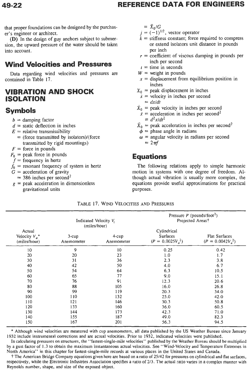
Data regarding wind velocities and pressures are
contained in Table 17.
VIBRATION AND
SHOCK
ISOLATION
Symbols
b
=
damping factor
d
=
static deflection in inches
E
=
relative transmissibility
=
(force transmitted by isolators)/(force
transmitted by rigid mountings)
F
=
force in pounds
Fo
=
peak force in pounds
f
=
frequency in hertz
fo
=
resonant frequency of system in hertz
G
=
acceleration of gravity
g
=
peak acceleration in dimensionless
=
386
inches per second’
gravitational units
Xo/G
(-I)”~, vector operator
stiffness constant; force required to compress
or extend isolators unit distance in pounds
per inch
coefficient of viscous damping in pounds per
inch per second
time in seconds
weight in pounds
displacement from equilibrium position in
inches
peak displacement in inches
velocity in inches per second
dxldt
peak velocity in inches per second
acceleration in inches per second’
d2xldt2
peak acceleration in inches per second’
phase angle in radians
angular velocity in radians per second
2Tf
Equations
The following relations apply to simple harmonic
motion in systems with one degree of freedom. Al-
though actual vibration is usually more complex, the
equations provide useful approximations for practical
purposes.
TABLE
17.
WIND
VELOCITIES AND
PRESSURES
~~
Pressure
P
(pounds/foot2)
Indicated Velocity Projected Areast
(miledhour)
Actual Cylindrical
Velocity V,* 3-cup
4-cup
Surfaces Flat Surfaces
(miledhour)
Anemometer Anemometer
(P
=
0.0025V2)
(P
=
O.O042V,2)
10
9 10 0.25
0.42
20
20 23
1
.o
1.7
40 42
50
4.0 6.7
50
54
64
6.3
10.5
60 65 77
9.0
15.1
70 76 91 12.3 20.6
80 88 105 16.0 26.8
90 99 119
20.3
34.0
100 110 132 25.0 42.0
110 121 146 30.3 50.8
120 133 160 36.0 60.5
130 144 173 42.3 71.0
140 155 187 49.0 82.3
30 31 36 2.3 3.8
150 167
20
1 56.3 94.5
*
Although wind velocities are measured with cup anemometers, all data published by the
US
Weather Bureau since January
1932 include instrumental corrections and
are
actual velocities. Prior to 1932, indicated velocities were published.
In
calculating pressures on structures, the “fastest-single-mile velocities” published by the Weather Bureau should he multiplied
by a gust factor of 1.3 to obtain the maximum instantaneous actual velocities. See “Wind-Velocity and Temperature Extremes in
North America” in this chapter for fastest-single-mile records at various places in the United States and Canada.
t
The American Bridge Company equations given here are based on a ratio of 25/42 for pressures
on
cylindrical and flat surfaces,
respectively, while the Electronic Industries Association specifies a ratio of 213. The actual ratio varies in a complex manner with
Reynolds number, shape, and size of the exposed object.
MISCELLANEOUS
F
=
W(Z/G)
F,
=
wg
DATA
49-23
x
=
Xo
sin(ot
+
4)
(Eq.
3)
(E¶.
4)
x,
=
9.77 g/f2
Xo
=
oxo
=
6.28fX0
=
61.4g/f
X,
=
w2X,
=
39.5f2X,
=
386s
(Eq.
5)
(Eq.
6)
When damping is neglected
fo
=
3.13/di/z
(Eq.
12)
E
=
9.77/(df2
-
9.77)
(Eq.
13)
Acceleration
r
-
j(k/o)
r
+
j[(oW/G)
-
k/w]
The intensity of vibratory forces is often defined in
terms of
g
values. From Eq.
2,
it is apparent, for
example, that a peak acceleration of
log
on a body will
result in a reactionary force by the body equal to
10
If
an object is mounted on vibration isolators, the
accelerations
of
the vehicle are transmitted to the object
(or vice versa) in an amplitude and phase that depend on
the elastic flexing of the isolators
in
the direction
in
which the accelerations (dynamic forces) are applied.
E=
1
fo
=
3.13
(k/W)'/*
(Eq.
8)
b
=
9.77r/(kW)"2
(Eq.
9)
times its weight.
For critical damping,
b
=
1.
Neglecting dissipation
(b
=
O),
or atf6
=
(2)"2
for
any degree of damping
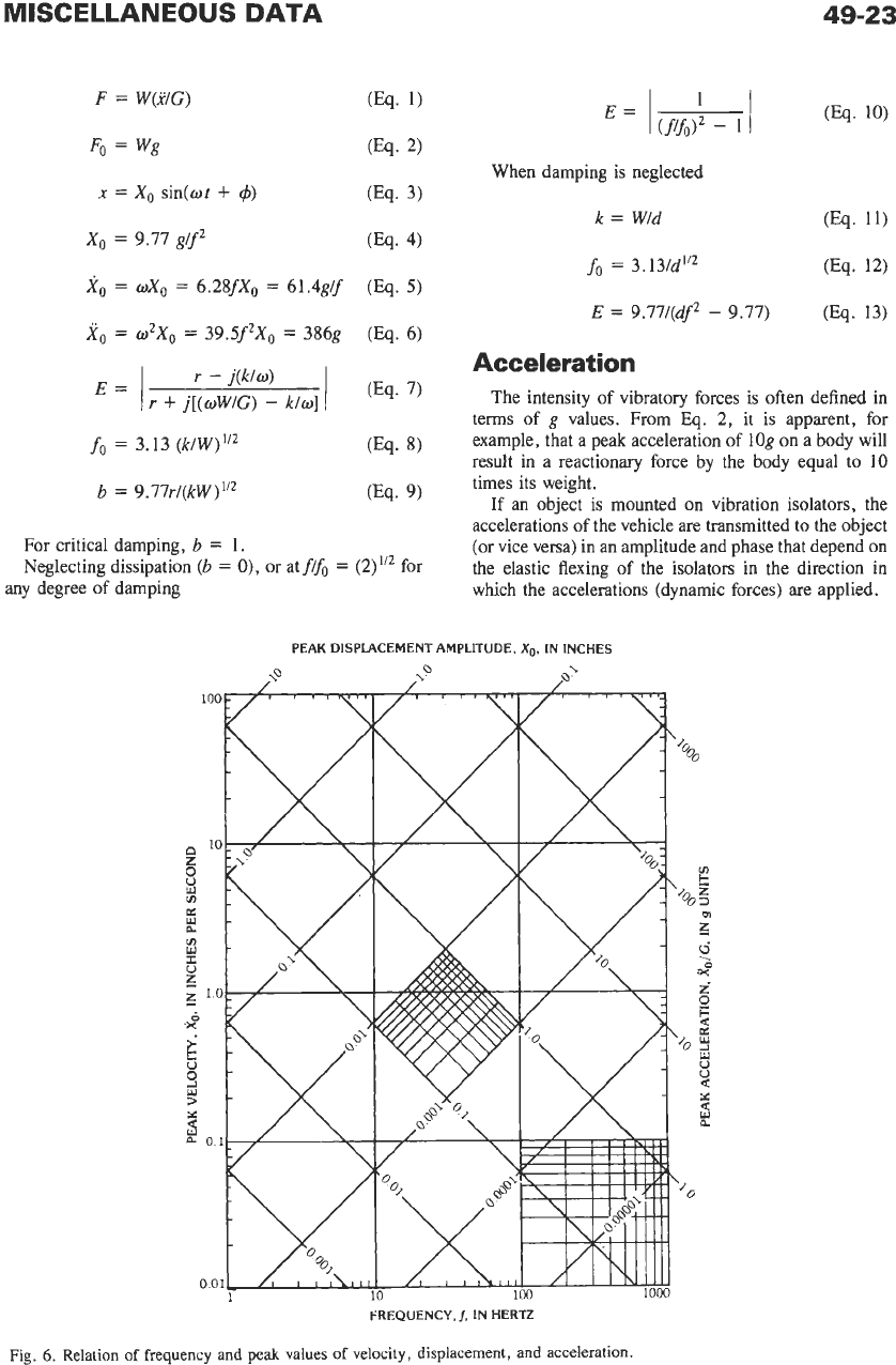
PEAK DISPLACEMENT AMPLITUDE,
Xo.
IN
INCHES
FREQUENCY,
I,
IN
HERTZ
Fig.
6.
Relation
of
frequency and
peak
values of velocity,
displacement,
and acceleration.