Munson B.R. Fundamentals of Fluid Mechanics
Подождите немного. Документ загружается.

To further demonstrate the use of the linear momentum equation 1Eq. 5.222, we consider
another one-dimensional flow example before moving on to other facets of this important
equation.
5.2 Newton’s Second Law—The Linear Momentum and Moment-of-Momentum Equations 207
Fluids in the News
Motorized surfboard When Bob Montgomery, a former pro-
fessional surfer, started to design his motorized surfboard
(called a jet board), he discovered that there were many engi-
neering challenges to the design. The idea is to provide surfing
to anyone, no matter where they live, near or far from the ocean.
The rider stands on the device like a surfboard and steers it like
a surfboard by shifting his/her body weight. A new, sleek, com-
pact 45-horsepower engine and pump was designed to fit within
the surfboard hull. Thrust is produced in response to the change
in linear momentum of the water stream as it enters through the
inlet passage and exits through an appropriately designed noz-
zle. Some of the fluid dynamic problems associated with de-
signing the craft included one-way valves so that water does not
get into the engine (at both the intake or exhaust ports), buoy-
ancy, hydrodynamic lift, drag, thrust, and hull stability. (See
Problem 5.68.)
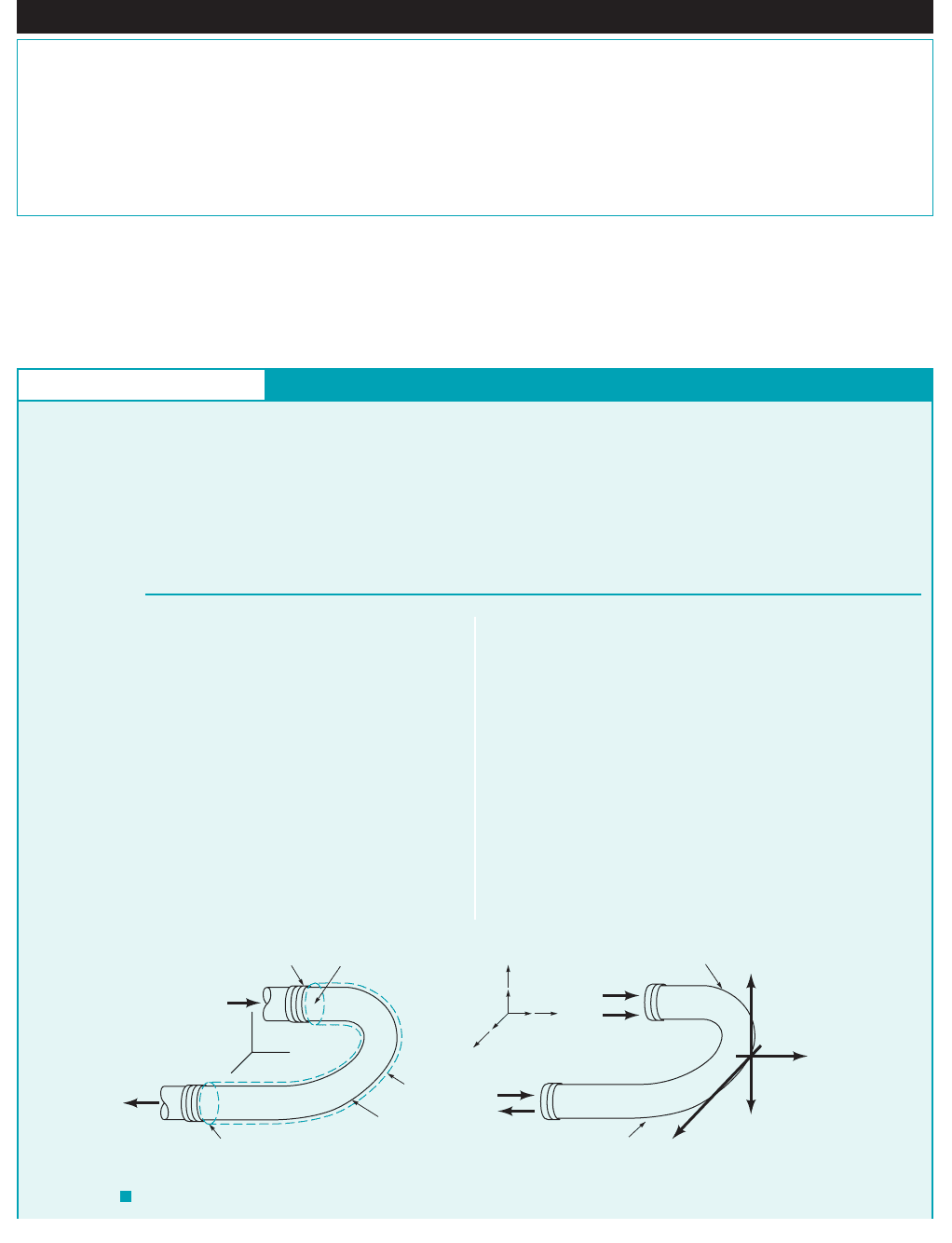
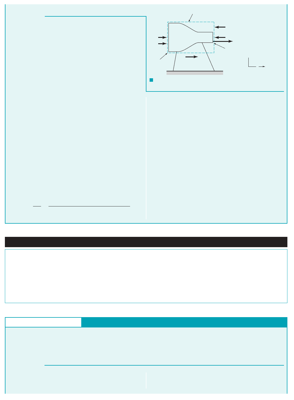
GIVEN Water flows through a horizontal, pipe bend as
illustrated in Fig. E5.12a. The flow cross-sectional area is con-
stant at a value of through the bend. The magnitude of the
flow velocity everywhere in the bend is axial and The
absolute pressures at the entrance and exit of the bend are 30 psia
and 24 psia, respectively.
50 ft
Ⲑ
s.
0.1 ft
2
180°
S
OLUTION
Linear Momentum—Pressure and Change in Flow Direction
At sections 112and 122, the flow is in the y direction and therefore
at both cross sections. There is no x direction momentum
flow into or out of the control volume and we conclude from Eq. 1
that
(Ans)
For the y direction, we get from Eq. 5.22
(2)
For one-dimensional flow, the surface integral in Eq. 2 is easy to
evaluate and Eq. 2 becomes
(3)1⫹v
1
21⫺m
#
1
2⫹ 1⫺v
2
21⫹m
#
2
2⫽ F
Ay
⫹ p
1
A
1
⫹ p
2
A
2
冮
cs
vrV ⴢ nˆ dA ⫽ F
Ay
⫹ p
1
A
1
⫹ p
2
A
2
F
Ax
⫽ 0
u ⫽ 0
E
XAMPLE 5.12
Since we want to evaluate components of the anchoring force to
hold the pipe bend in place, an appropriate control volume 1see
dashed line in Fig. E5.12a2contains the bend and the water in the
bend at an instant. The horizontal forces acting on the contents of
this control volume are identified in Fig. E5.12b. Note that the
weight of the water is vertical 1in the negative z direction2and
does not contribute to the x and y components of the anchoring
force. All of the horizontal normal and tangential forces exerted
on the fluid and the pipe bend are resolved and combined into the
two resultant components, and These two forces act on
the control volume contents, and thus for the x direction, Eq. 5.22
leads to
(1)
冮
cs
urV ⴢ nˆ dA ⫽ F
Ax
F
Ay
.F
Ax
FIND Calculate the horizontal 1x and y2components of the an-
choring force required to hold the bend in place.
z
y
x
V
= 50 ft/s
Section (1)
A = 0.1 ft
2
V =
50 ft/s
Section (2)
Control
volume
180° pipe bend
(
a)
x
u
v y
w
z
p
1
A
1
v
1
v
2
p
2
A
2
F
Az
F
Ay
ᐃ
F
Ax
Control volume
Pipe bend
and water
(b)
F I G U R E E5.12
JWCL068_ch05_187-262.qxd 9/23/08 9:56 AM Page 207
In Examples 5.10 and 5.12 the force exerted on a flowing fluid resulted in a change in flow
direction only. This force was associated with constraining the flow, with a vane in Example 5.10,
and with a pipe bend in Example 5.12. In Example 5.11 the force exerted on a flowing fluid
resulted in a change in velocity magnitude only. This force was associated with a converging
nozzle. Anchoring forces are required to hold a vane or conduit stationary. They are most easily
estimated with a control volume that contains the vane or conduit and the flowing fluid involved.
Alternately, two separate control volumes can be used, one containing the vane or conduit only
and one containing the flowing fluid only.
208 Chapter 5 ■ Finite Control Volume Analysis
Note that the y component of velocity is positive at section 112but
is negative at section 122. Also, the mass flowrate term is negative
at section 1121flow in2and is positive at section 1221flow out2. From
the continuity equation 1Eq. 5.122, we get
(4)
and thus Eq. 3 can be written as
(5)
Solving Eq. 5 for we obtain
(6)
From the given data we can calculate the mass flowrate, from
Eq. 5.6 as
For determining the anchoring force, the effects of atmos-
pheric pressure cancel and thus gage pressures for and are
appropriate. By substituting numerical values of variables into
Eq. 6, and using the fact that we get
(Ans)
The negative sign for is interpreted as meaning that the y
component of the anchoring force is actually in the negative y
direction, not the positive y direction as originally indicated in
Fig. E5.12b.
COMMENT As with Example 5.11, the anchoring force for
the pipe bend is independent of the atmospheric pressure. How-
ever, the force that the bend puts on the fluid inside of it,
R
y
,
F
Ay
F
Ay
⫽⫺970 lb ⫺ 220 lb ⫺ 134 lb ⫽⫺1324 lb
⫺ 124 psia ⫺ 14.7 psia21144 in.
2
Ⲑ
ft
2
210.1 ft
2
2
⫺ 130 psia ⫺ 14.7 psia21144 in.
2
Ⲑ
ft
2
210.1 ft
2
2
F
Ay
⫽⫺19.70 slugs
Ⲑ
s2150 ft
Ⲑ
s ⫹ 50 ft
Ⲑ
s2
1 lb ⫽ 1 slug ⴢ ft
Ⲑ
s
2
p
2
p
1
F
Ay
,
⫽ 9.70 slugs
Ⲑ
s
m
#
⫽ r
1
A
1
v
1
⫽ 11.94 slugs
Ⲑ
ft
3
210.1 ft
2
2150 ft
Ⲑ
s2
m
#
,
F
Ay
⫽⫺m
#
1v
1
⫹ v
2
2⫺ p
1
A
1
⫺ p
2
A
2
F
Ay
⫺m
#
1v
1
⫹ v
2
2⫽ F
Ay
⫹ p
1
A
1
⫹ p
2
A
2
m
#
⫽ m
#
1
⫽ m
#
2
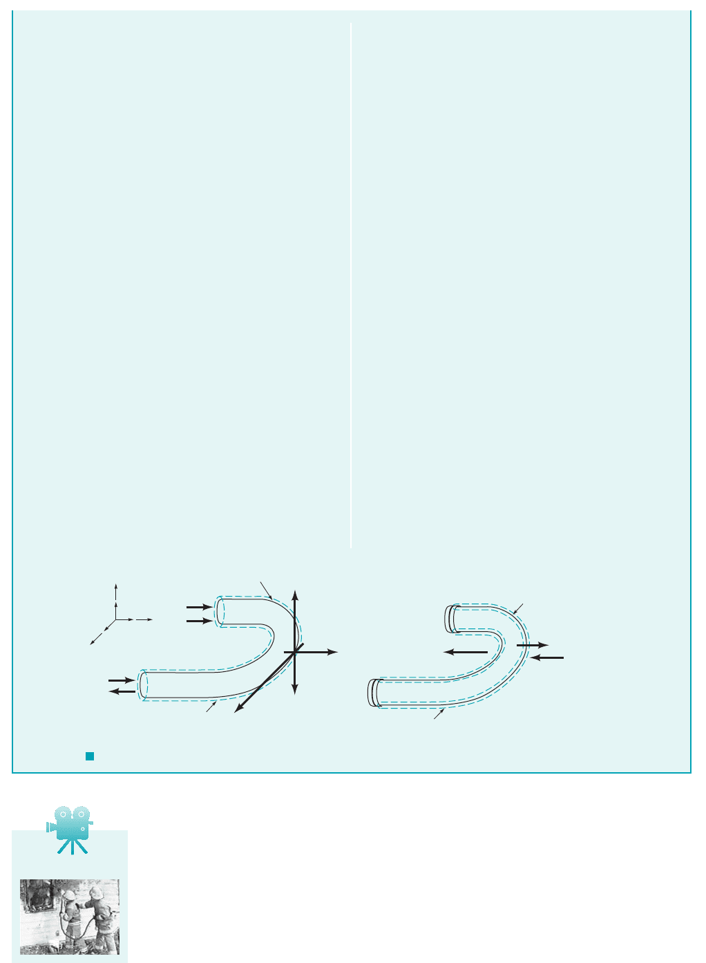
depends on the atmospheric pressure. We can see this by using a
control volume which surrounds only the fluid within the bend as
shown in Fig. E5.12c. Application of the momentum equation to
this situation gives
where and must be in terms of absolute pressure because
the force between the fluid and the pipe wall, is the complete
pressure effect 1i.e., absolute pressure2. We see that forces exerted
on the flowing fluid result in a change in its velocity direction 1a
change in linear momentum2.
Thus, we obtain
(7)
We can use the control volume that includes just the pipe
bend 1without the fluid inside it2as shown in Fig. E5.12d to
determine the anchoring force component in the y direction
necessary to hold the bend stationary. The y component of the
momentum equation applied to this control volume gives
(8)
where is given by Eq. 7. The term represents the
net pressure force on the outside portion of the control volume.
Recall that the pressure force on the inside of the bend is ac-
counted for by By combining Eqs. 7 and 8 and using the fact that
, we obtain
in agreement with the original answer obtained using the control
volume of Fig. E5.12b.
⫽⫺1324 lb
F
Ay
⫽⫺1748 lb ⫹ 2117 lb
Ⲑ
ft
2
10.1 ft
2
⫹ 0.1 ft
2
2
p
atm
⫽ 14.7 lb
Ⲑ
in.
2
1144 in.
2
Ⲑ
ft
2
2⫽ 2117 lb
Ⲑ
ft
2
R
y
.
p
atm
1A
1
⫹ A
2
2R
y
F
Ay
⫽ R
y
⫹ p
atm
1A
1
⫹ A
2
2
F
Ay
,
⫽⫺1748 lb
⫺ 124 psia21144 in.
2
Ⲑ
ft
2
210.1 ft
2
2
⫺ 130 psia21144 in.
2
Ⲑ
ft
2
210.1 ft
2
2
R
y
⫽⫺19.70 slugs
Ⲑ
s2150 ft
Ⲑ
s ⫹ 50 ft
Ⲑ
s2
R
y
,
p
2
p
1
R
y
⫽⫺m
#
1v
1
⫹ v
2
2⫺ p
1
A
1
⫺ p
2
A
2
F I G U R E E5.12 cont.
Control volume
Water in 180° bend
p
2
A
2
p
1
A
1
v
2
v
1
(c)
Pipe bend only
(
d)
R
y
p
atm
(A
1
+ A
2
)
R
z
R
y
R
x
ᐃ
Control volume
F
Ay
x
u
v y
w
z
V5.8 Fire hose
JWCL068_ch05_187-262.qxd 9/23/08 9:57 AM Page 208
5.2 Newton’s Second Law—The Linear Momentum and Moment-of-Momentum Equations 209
GIVEN Air flows steadily between two cross sections in a long,
straight portion of 4-in. inside diameter pipe as indicated in Fig.
E5.13, where the uniformly distributed temperature and pressure at
each cross section are given. If the average air velocity at section 122
is 1000 ft兾s, we found in Example 5.2 that the average air velocity at
section 112must be 219 ft兾s. Assume uniform velocity distributions
at sections 112and 122.
S
OLUTION
F I G U R E E5.13
Linear Momentum—Pressure, Change in Speed, and Friction
English Engineering 1EE2units are often used for this kind of
flow. The gas constant, R, for air in EE units is
(8)
Thus, from Eqs. 5 and 8
or
(Ans)
COMMENT For this compressible flow, the pressure differ-
ence drives the motion which results in a frictional force, R
x
, and
an acceleration of the fluid (i.e., a velocity magnitude increase).
For a similar incompressible pipe flow, a pressure difference re-
sults in fluid motion with a frictional force only (i.e., no change in
velocity magnitude).
R
x
793 lb
1025 lb 232 lb
32.1741lbm ⴢ ft2
1lb ⴢ s
2
2
19.57 lbm211000 ft
s 219 ft
s2
R
x
p14 in.2
2
4
1100 psia 18.4 psia2
p14 in.2
2
41144 in.
2
ft
2
2
11000 ft
s2 9.57 lbm
s
Hence, m
#
118.4 psia21144 in.
2
ft
2
2
353.31ft
#
lb2
1lbm
#
°R24 1453 °R2
R
17161ft
#
lb2
1slug
#
°R2
32.1741lbm
slug2
53.31ft
#
lb2
1lbm
#
°R2
Control volume
Section (1)
Flow
V
1
V
2
=
1000 ft/s
p
2
A
2
p
1
A
1
p
1
= 100 psia
T
1
= 540 °R
Section (2)Pipe
p
2
= 18.4 psia
T
2
= 453 °R
R
x
y
x
E
XAMPLE 5.13
The control volume of Example 5.2 is appropriate for this prob-
lem. The forces acting on the air between sections 112and 122are
identified in Fig. E5.13. The weight of air is considered negligibly
small. The reaction force between the wetted wall of the pipe and
the flowing air, is the frictional force sought. Application of
the axial component of Eq. 5.22 to this control volume yields
(1)
The positive x direction is set as being to the right. Furthermore,
for uniform velocity distributions 1one-dimensional flow2, Eq. 1
becomes
(2)
From conservation of mass 1Eq. 5.122we get
(3)
so that Eq. 2 becomes
(4)
Solving Eq. 4 for we get
(5)
The equation of state gives
(6)
and the equation for area is
(7)
Thus, from Eqs. 3, 6, and 7
m
#
a
p
2
RT
2
b a
pD
2
2
4
b u
2
A
2
pD
2
2
4
A
2
r
2
p
2
RT
2
R
x
A
2
1p
1
p
2
2 m
#
1u
2
u
1
2
R
x
,
m
#
1u
2
u
1
2R
x
A
2
1p
1
p
2
2
m
#
m
#
1
m
#
2
1u
1
21m
#
1
2 1u
2
21m
#
2
2R
x
p
1
A
1
p
2
A
2
冮
cs
urV ⴢ nˆ dA R
x
p
1
A
1
p
2
A
2
R
x
,
FIND Determine the frictional force exerted by the pipe wall on
the air flow between sections 112and 122.
GIVEN Consider the flow of Example 5.4 to be vertically
upward.
Linear Momentum—Weight, Pressure, Friction,
and Nonuniform Velocity Profile
E
XAMPLE 5.14
FIND Develop an expression for the fluid pressure drop that
occurs between sections 112and 122.
JWCL068_ch05_187-262.qxd 9/23/08 9:57 AM Page 209
210 Chapter 5 ■ Finite Control Volume Analysis
S
OLUTION
been identical, a condition we call “fully developed” flow. Then,
the pressure drop, would be due only to pipe wall fric-
tion and the weight of the water column. If in addition to being
fully developed, the flow involved negligible weight effects 1for
example, horizontal flow of liquids or the flow of gases in any
direction2the drop in pressure between any two sections,
would be a result of pipe wall friction only.
Note that although the average velocity is the same at section
112as it is at section 122 the momentum flux
across section 112is not the same as it is across section 122. If it
were, the left-hand side of Eq. 142would be zero. For this nonuni-
form flow the momentum flux can be written in terms of the av-
erage velocity, and the momentum coefficient, as
Hence the momentum flux can be written as
where 1 for uniform flow2and 1 for
any nonuniform flow2.
b 7 1
b
2
⫽ 4
Ⲑ
3
b ⫽ 1
b
1
⫽ 1
冮
cs
wrV ⴢ nˆ dA ⫽⫺b
1
w
2
1
rpR
2
⫹ b
2
w
2
1
rpR
2
b ⫽
冮
wrV ⴢ nˆ dA
rV
2
A
b,V
,
1V
1
⫽ V
2
⫽ w
1
2,
p
1
⫺ p
2
,
p
1
⫺ p
2
,
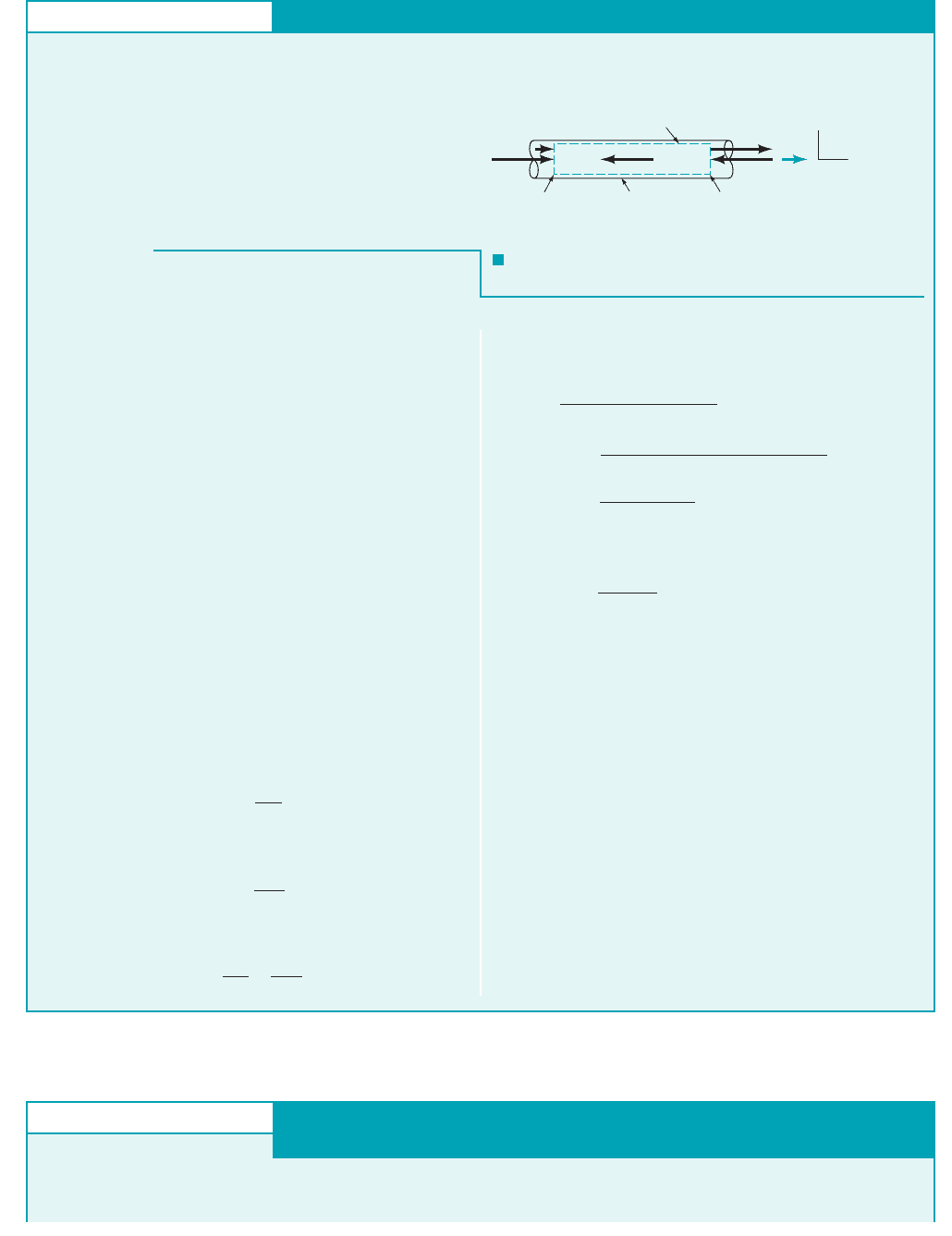
A control volume 1see dashed lines in Fig. E5.142that includes
only fluid from section 112to section 122is selected. The forces
acting on the fluid in this control volume are identified in Fig.
E5.14. The application of the axial component of Eq. 5.22 to the
fluid in this control volume results in
(1)
where is the resultant force of the wetted pipe wall on the
fluid. Further, for uniform flow at section 112, and because the
flow at section 122is out of the control volume, Eq. 1 becomes
(2)
The positive direction is considered up. The surface integral over
the cross-sectional area at section 122, is evaluated by using
the parabolic velocity profile obtained in Example 5.4,
as
or
(3)
Combining Eqs. 2 and 3 we obtain
(4)
Solving Eq. 4 for the pressure drop from section 112to section 122,
we obtain
(Ans)
COMMENT We see that the drop in pressure from section 112
to section 122occurs because of the following:
1. The change in momentum flow between the two sections
associated with going from a uniform velocity profile to
a parabolic velocity profile,
2. Pipe wall friction,
3. The weight of the water column, ; a hydrostatic pres-
sure effect.
If the velocity profiles had been identically parabolic at sections
112and 122, the momentum flowrate at each section would have
w
R
z
rw
1
2
Ⲑ
3
p
1
⫺ p
2
⫽
rw
2
1
3
⫹
R
z
A
1
⫹
w
A
1
p
1
⫺ p
2
,
⫺w
1
2
rpR
2
⫹
4
3
w
2
1
rpR
2
⫽ p
1
A
1
⫺ R
z
⫺ w ⫺ p
2
A
2
冮
A
2
w
2
rw
2
dA
2
⫽ 4prw
2
1
R
2
3
⫽ 2pr
冮
R
0
12w
1
2
2
c1 ⫺ a
r
R
b
2
d
2
r dr
冮
A
2
w
2
rw
2
dA
2
⫽ r
冮
R
0
w
2
2
2pr dr
w
2
⫽ 2w
1
31 ⫺ 1r
Ⲑ
R2
2
4,
A
2
,
⫺ w ⫺ p
2
A
2
1⫹w
1
21⫺m
#
1
2⫹
冮
A
2
1⫹w
2
2r1⫹w
2
dA
2
2⫽ p
1
A
1
⫺ R
z
R
z
冮
cs
wrV ⴢ nˆ dA ⫽ p
1
A
1
⫺ R
z
⫺ w ⫺ p
2
A
2
F I G U R E E5.14
Flow
p
2
A
2
ᐃ
R
z
R
r
Fluid only
Control volume
Section (1)
Section (2)
w
2
= 2w
1
1 –
( )
[]
r
–
R
2
p
1
A
1
w
1
x
u
v
y
w
z
GIVEN A static thrust stand as sketched in Fig. E5.15 is to be
designed for testing a jet engine. The following conditions are
known for a typical test: Intake air velocity exhaust gas
velocity intake cross-sectional area intake⫽ 1 m
2
;
⫽ 500 m
Ⲑ
s;
⫽ 200 m
Ⲑ
s;
Linear Momentum—Thrust
E
XAMPLE 5.15
staticpressure kPa 1abs2; intakestatic temper-
ature exhaust static pressure 0 kPa 1abs2.
FIND Estimate the nominal anchoring force for which to design.
⫽ 101 kPa⫽⫽ 268 K;
⫽ 78.5 kPa⫽⫺22.5
JWCL068_ch05_187-262.qxd 9/23/08 9:58 AM Page 210
5.2 Newton’s Second Law—The Linear Momentum and Moment-of-Momentum Equations 211
S
OLUTION
Thus,
(6)
Finally, combining Eqs. 5 and 6 and substituting given data with
we obtain
or
(Ans)
COMMENT The force of the thrust stand on the engine is di-
rected toward the right. Conversely, the engine pushes to the left
on the thrust stand 1or aircraft2.
F
th
⫽ 22,500 N ⫹ 61,200 N ⫽ 83,700 N
⫹ 1204 kg
Ⲑ
s21500 m
Ⲑ
s ⫺ 200 m
Ⲑ
s231 N
Ⲑ
1kg
#
m
Ⲑ
s
2
24
F
th
⫽⫺11 m
2
21⫺22.5 kPa211000 Pa
Ⲑ
kPa2311N
Ⲑ
m
2
2
Ⲑ
Pa4
p
2
⫽ 0,
⫽ 204 kg
Ⲑ
s
m
#
⫽ r
1
A
1
u
1
⫽ 11.02 kg
Ⲑ
m
3
211 m
2
21200 m
Ⲑ
s2
The cylindrical control volume outlined with a dashed line in
Fig. E5.15 is selected. The external forces acting in the axial di-
rection are also shown. Application of the momentum equation
1Eq. 5.222to the contents of this control volume yields
(1)
where the pressures are absolute. Thus, for one-dimensional flow,
Eq. 1 becomes
(2)
The positive direction is to the right. The conservation of mass
equation 1Eq. 5.122leads to
(3)
Combining Eqs. 2 and 3 and using gage pressure we obtain
(4)
Solving Eq. 4 for the thrust force, we obtain
(5)
We need to determine the mass flowrate, to calculate and
to calculate we need From the ideal gas equation
of state
⫽ 1.02 kg
Ⲑ
m
3
r
1
⫽
p
1
RT
1
⫽
178.5 kPa211000 Pa
Ⲑ
kPa2311N
Ⲑ
m
2
2
Ⲑ
Pa4
1286.9 J
Ⲑ
kg
#
K21268 K211 N
#
m
Ⲑ
J2
r
1
.m
#
⫽ r
1
A
1
u
1
,
F
th
,m
#
,
F
th
⫽⫺p
1
A
1
⫹ p
2
A
2
⫹ m
#
1u
2
⫺ u
1
2
F
th
,
m
#
1u
2
⫺ u
1
2⫽ p
1
A
1
⫺ p
2
A
2
⫹ F
th
m
#
⫽ m
#
1
⫽ r
1
A
1
u
1
⫽ m
#
2
⫽ r
2
A
2
u
2
⫺ 1
p
2
⫺ p
atm
2A
2
⫹ F
th
1⫹u
1
21⫺m
#
1
2⫹ 1⫹u
2
21⫹m
#
2
2⫽ 1
p
1
⫺ p
atm
2A
1
⫺ p
atm
1A
1
⫺ A
2
2
冮
cs
urV ⴢ nˆ dA ⫽ p
1
A
1
⫹ F
th
⫺ p
2
A
2
F I G U R E E5.15
Control volume
Section (1)
Section (2)
p
1
A
1
p
2
A
2
p
atm
(A
1
– A
2
)
u
1
F
th
u
2
z
xu
Fluids in the News
Bow thrusters In the past, large ships required the use of tugboats
for precise maneuvering, especially when docking. Nowadays,
most large ships (and many moderate to small ones as well) are
equipped with bow thrusters to help steer in close quarters. The
units consist of a mechanism (usually a ducted propeller mounted
at right angles to the fore/aft axis of the ship) that takes water from
one side of the bow and ejects it as a water jet on the other side.
The momentum flux of this jet produces a starboard or port force
on the ship for maneuvering. Sometimes a second unit is installed
in the stern. Initially used in the bows of ferries, these versatile
control devices have became popular in offshore oil servicing
boats, fishing vessels, and larger ocean-going craft. They permit
unassisted maneuvering alongside of oilrigs, vessels, loading plat-
forms, fishing nets, and docks. They also provide precise control at
slow speeds through locks, narrow channels, and bridges, where
the rudder becomes very ineffective. (See Problem 5.69.)
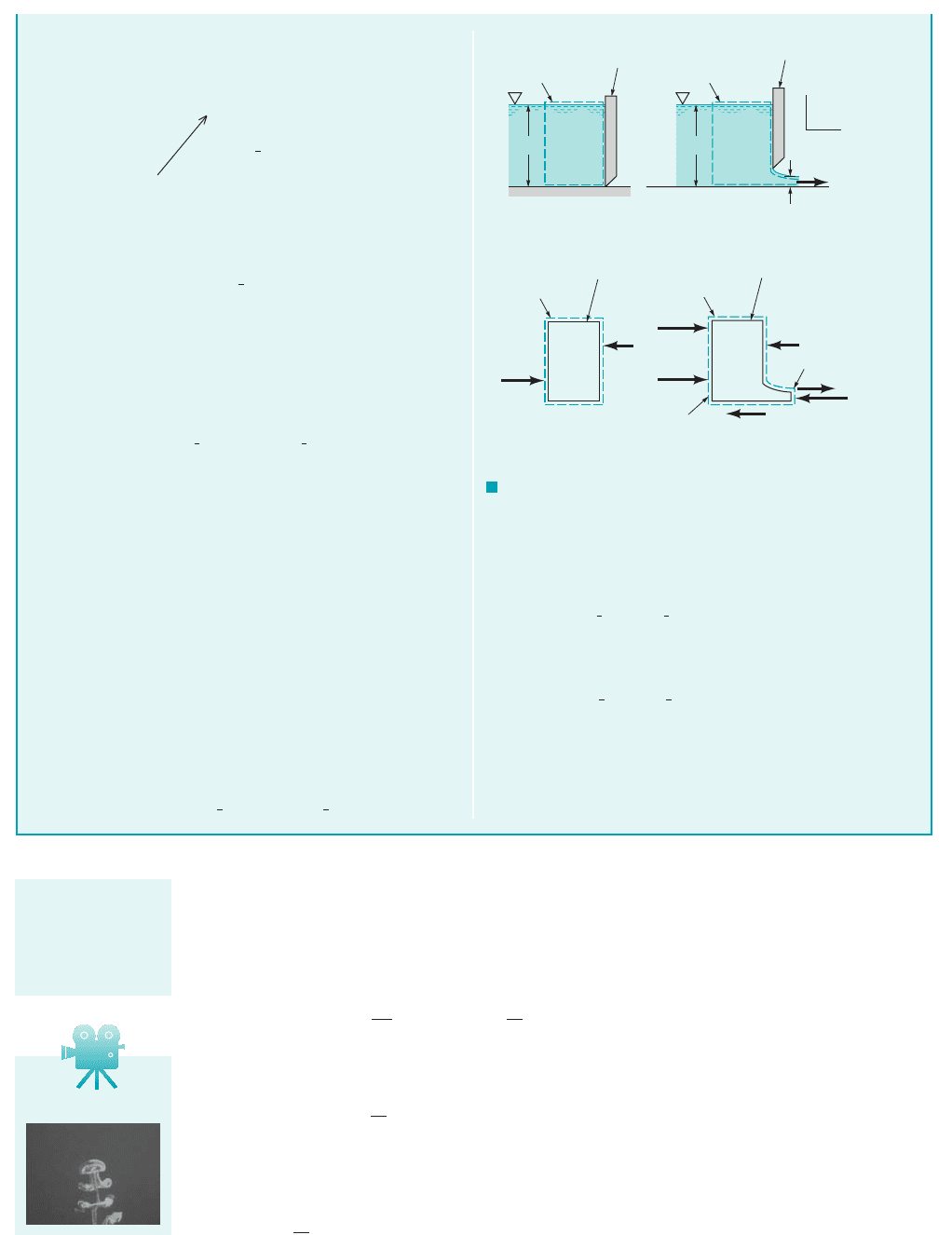
GIVEN A sluice gate across a channel of width b is shown in
the closed and open positions in Figs. E5.16a and E5.16b.
S
OLUTION
Linear Momentum—Nonuniform Pressure
volume used in each case is indicated with dashed lines in Figs.
E5.16a and E5.16b.
E
XAMPLE 5.16
We will answer this question by comparing expressions for the
horizontal reaction force, between the gate and the water
when the gate is closed and when the gate is open. The control
R
x
,
FIND Is the anchoring force required to hold the gate in place
larger when the gate is closed or when it is open?
JWCL068_ch05_187-262.qxd 9/23/08 9:58 AM Page 211
All of the linear momentum examples considered thus far have involved stationary and non-
deforming control volumes which are thus inertial because there is no acceleration. A nondeform-
ing control volume translating in a straight line at constant speed is also inertial because there is
no acceleration. For a system and an inertial, moving, nondeforming control volume that are both
coincident at an instant of time, the Reynolds transport theorem 1Eq. 4.232leads to
(5.23)
When we combine Eq. 5.23 with Eqs. 5.19 and 5.20, we get
(5.24)
When the equation relating absolute, relative, and control volume velocities 1Eq. 5.142is used with
Eq. 5.24, the result is
(5.25)
0
0t
冮
cv
1W V
cv
2r dV
冮
cs
1W V
cv
2rW ⴢ nˆ dA
a
F
contents of the
control volume
0
0t
冮
cv
Vr dV
冮
cs
VrW ⴢ nˆ dA
a
F
contents of the
control volume
D
Dt
冮
sys
Vr dV
0
0t
冮
cv
Vr dV
冮
cs
VrW ⴢ nˆ dA
212 Chapter 5 ■ Finite Control Volume Analysis
When the gate is closed, the horizontal forces acting on the
contents of the control volume are identified in Fig. E5.16c. Ap-
plication of Eq. 5.22 to the contents of this control volume yields
0 1no flow2
(1)
Note that the hydrostatic pressure force, is used. From
Eq. 1, the force exerted on the water by the gate 1which is equal to
the force necessary to hold the gate stationary2is
(2)
which is equal in magnitude to the hydrostatic force exerted on
the gate by the water.
When the gate is open, the horizontal forces acting on the con-
tents of the control volume are shown in Fig. E5.16d. Application
of Eq. 5.22 to the contents of this control volume leads to
(3)
Note that because the water at sections (1) and (2) is flowing
along straight, horizontal streamlines, the pressure distribution at
those locations is hydrostatic, varying from zero at the free sur-
face to times the water depth at the bottom of the channel (see
Chapter 3, Section 3.4). Thus, the pressure forces at sections (1)
and (2) (given by the pressure at the centroid times the area) are
and respectively. Also, the frictional force be-
tween the channel bottom and the water is specified as The
surface integral in Eq. 3 is nonzero only where there is flow
across the control surface. With the assumption of uniform veloc-
ity distributions,
(4)
Thus, Eqs. 3 and 4 combine to form
(5)ru
2
1
Hb ru
2
2
hb
1
2
gH
2
b R
x
1
2
gh
2
b F
f
冮
cs
urV ⴢ nˆ dA 1u
1
2r1u
1
2Hb 1u
2
2r1u
2
2hb
F
f
.
gh
2
b
2,gH
2
b
2
g
冮
cs
urV ⴢ nˆ dA
1
2
gH
2
b R
x
1
2
gh
2
b F
f
R
x
1
2
gH
2
b
gH
2
b
2,
冮
cs
urV ⴢ nˆ dA
1
2
gH
2
b R
x
If the upstream velocity, is much less than so that the
contribution of the incoming momentum flow to the control sur-
face integral can be neglected and from Eq. 5 we obtain
(6)
By using the continuity equation, Eq. (6)
can be rewritten as
(7)
Hence, since , by comparing the expressions for R
x
(Eqs.
2 and 7) we conclude that the reaction force between the gate and
the water (and therefore the anchoring force required to hold the
gate in place) is smaller when the gate is open than when it is
closed.
(Ans)
u
2
7 u
1
R
x
1
2
H
2
b
1
2
h
2
b F
f
m
#
1u
2
u
1
2
m
#
bHu
1
bhu
2
,
R
x
1
2
gH
2
b
1
2
gh
2
b F
f
ru
2
2
hb
u
2
u
1
,
H h,
F I G U R E E5.16
H
Control volume
Closed sluice
gate
H
Control volume
Open sluice
gate
h
x
z
u
(a)(b)
Control volume
Water only
Control volume
Water only
u
1
R
x
u
2
( )
1
_
2
γ
H Hb
( )
1
_
2
γ
H Hb
( )
1
_
2
γ
h hb
F
f
Section
(1)
Section (2)
(c)(d)
R
x
V5.9 Jelly fish
The linear momen-
tum equation can
be written for a
moving control
volume.
JWCL068_ch05_187-262.qxd 9/23/08 9:58 AM Page 212
For a constant control volume velocity, and steady flow in the control volume reference frame,
(5.26)
Also, for this inertial, nondeforming control volume
(5.27)
For steady flow 1on an instantaneous or time-average basis2, Eq. 5.15 gives
(5.28)
Combining Eqs. 5.25, 5.26, 5.27, and 5.28, we conclude that the linear momentum equation for
an inertial, moving, nondeforming control volume that involves steady 1instantaneous or time-
average2flow is
(5.29)
Example 5.17 illustrates the use of Eq. 5.29.
冮
cs
WrW ⴢ nˆ dA ⫽
a
F
contents of the
control volume
冮
cs
rW ⴢ nˆ dA ⫽ 0
冮
cs
1W ⫹ V
cv
2rW ⴢ nˆ dA ⫽
冮
cs
WrW ⴢ nˆ dA ⫹ V
cv
冮
cs
rW ⴢ nˆ dA
0
0t
冮
cv
1W ⫹ V
cv
2r dV⫺⫽0
V
cv
,
5.2 Newton’s Second Law—The Linear Momentum and Moment-of-Momentum Equations 213
The linear momen-
tum equation for a
moving control vol-
ume involves the
relative velocity.
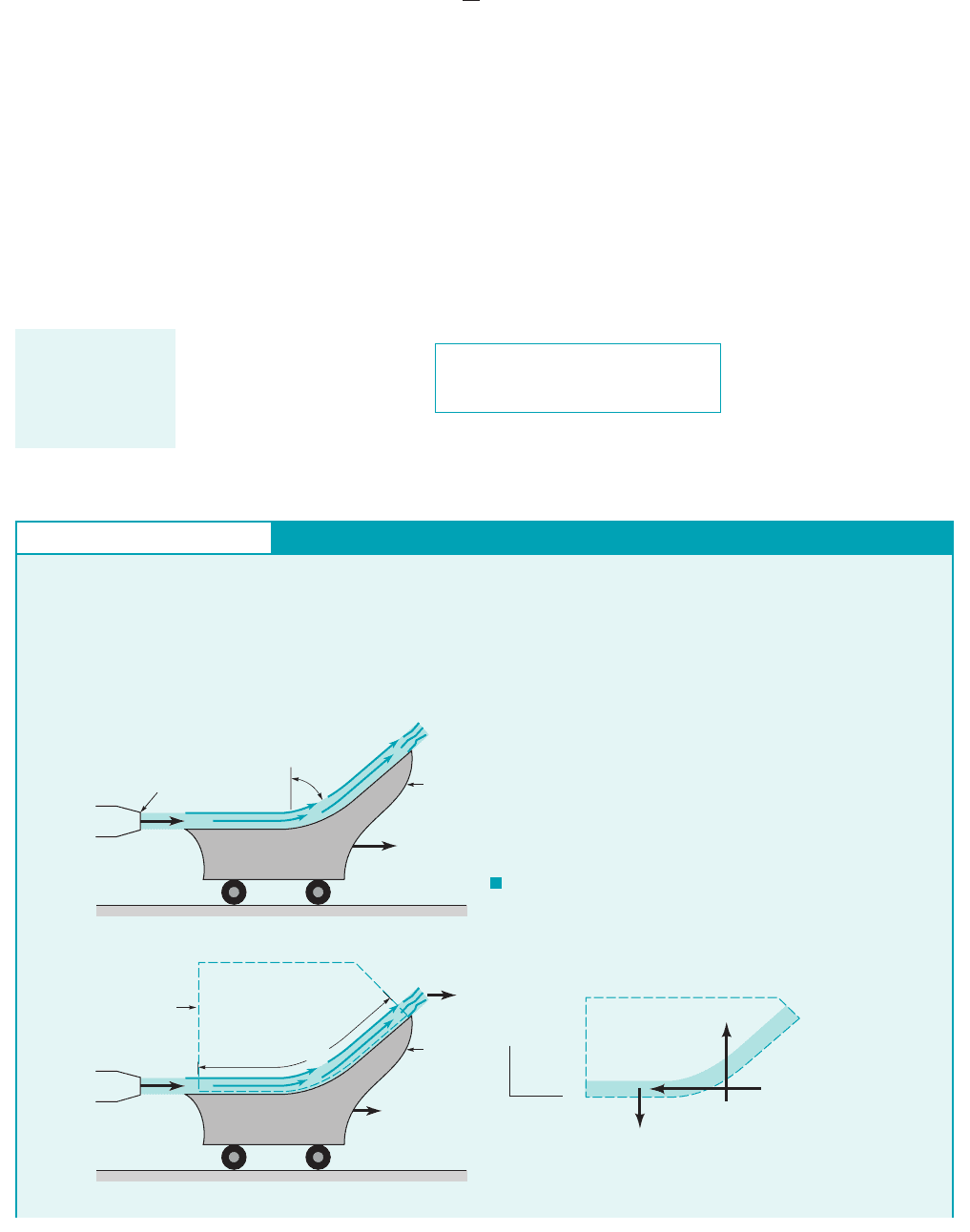
GIVEN A vane on wheels moves with constant velocity
when a stream of water having a nozzle exit velocity of is
turned by the vane as indicated in Fig. E5.17a. Note that
this is the same moving vane considered in Section 4.4.6
earlier. The speed of the water jet leaving the nozzle is 100 ft兾s,
45°
V
1
V
0
Linear Momentum—Moving Control Volume
E
XAMPLE 5.17
F I G U R E E5.17
Nozzle
V
1
V
0
A
1
= 0.006 ft
2
45°
Moving
vane
Nozzle
V
1
V
0
z
x
V
CV
= V
0
ᐃ
w
R
x
R
z
1 ft
Moving
vane
Moving
control
volume
(1)
(2)
(b)
(c)
(a)
and the vane is moving to the right with a constant speed of
20 ft兾s.
FIND Determine the magnitude and direction of the force, F,
exerted by the stream of water on the vane surface.
JWCL068_ch05_187-262.qxd 9/30/08 8:19 AM Page 213

214 Chapter 5 ■ Finite Control Volume Analysis
S
OLUTION
Combining results we get
or
Also,
where
Thus,
Combining the components we get
The angle of R from the x direction, is
The force of the water on the vane is equal in magnitude but op-
posite in direction from R; thus it points to the right and down at
an angle of from the x direction and is equal in magnitude
to 57.3 lb.
(Ans)
COMMENT The force of the fluid on the vane in the x-
direction, , is associated with x-direction motion of the
vane at a constant speed of . Since the vane is not accelerat-
ing, this x-direction force is opposed mainly by a wheel friction
force of the same magnitude. From basic physics we recall that the
power this situation involves is the product of force and speed. Thus,
All of this power is consumed by friction.
⫽ 0.79 hp
⫽
121.8 lb2120 ft
Ⲑ
s2
5501ft ⴢ lb2
Ⲑ
1hp ⴢ s2
p ⫽ R
x
V
0
20 ft
Ⲑ
s
R
x
⫽ 21.8 lb
67.6°
a ⫽ tan
⫺1
R
z
R
x
⫽ tan
⫺1
153 lb
Ⲑ
21.8 lb2⫽ 67.6°
a,
R ⫽ 2R
x
2
⫹ R
z
2
⫽ 3121.8 lb2
2
⫹ 153 lb2
2
4
1
Ⲑ
2
⫽ 57.3 lb
⫽ 52.6 lb ⫹ 0.37 lb ⫽ 53 lb
⫹ 162.4 lb
Ⲑ
ft
3
210.006 ft
2
211 ft2
R
z
⫽ 11.94 slugs
Ⲑ
ft
3
2180 ft
Ⲑ
s2
2
1sin 45°210.006 ft
2
2
w
w
⫽ rgA
1
/
R
z
⫽ rW
1
2
1sin 45°2A
1
⫹ w
w
⫽ 21.8 lb
R
x
⫽ 11.94 slugs
Ⲑ
ft
3
2180 ft
Ⲑ
s2
2
10.006 ft
2
211 ⫺ cos 45°2
R
x
⫽ rW
2
1
A
1
11 ⫺ cos 45°2
To determine the magnitude and direction of the force, F, exerted
by the water on the vane, we apply Eq. 5.29 to the contents of the
moving control volume shown in Fig. E5.17b. The forces acting
on the contents of this control volume are indicated in
Fig. E5.17c. Note that since the ambient pressure is atmospheric,
all pressure forces cancel each other out. Equation 5.29 is ap-
plied to the contents of the moving control volume in component
directions. For the x direction 1positive to the right2, we get
or
(1)
where
For the vertical or z direction 1positive up2we get
or
(2)
We assume for simplicity that the water flow is frictionless and that
the change in water elevation across the vane is negligible. Thus,
from the Bernoulli equation 1Eq. 3.72we conclude that the speed of
the water relative to the moving control volume, W, is constant or
The relative speed of the stream of water entering the control vol-
ume, is
The water density is constant so that
Application of the conservation of mass principle to the contents
of the moving control volume 1Eq. 5.162leads to
m
#
1
⫽ r
1
W
1
A
1
⫽ r
2
W
2
A
2
⫽ m
#
2
r
1
⫽ r
2
⫽ 1.94 slugs
Ⲑ
ft
3
W
1
⫽ V
1
⫺ V
0
⫽ 100 ft
Ⲑ
s ⫺ 20 ft
Ⲑ
s ⫽ 80 ft
Ⲑ
s ⫽ W
2
W
1
,
W
1
⫽ W
2
1⫹W
2
sin 45°21⫹m
#
2
2⫽ R
z
⫺ w
w
冮
cs
W
z
rW ⴢ nˆ dA ⫽ R
z
⫺ w
w
m
#
1
⫽ r
1
W
1
A
1
and
m
#
2
⫽ r
2
W
2
A
2
.
1⫹W
1
21⫺m
#
1
2⫹ 1⫹W
2
cos 45°21⫹m
#
2
2⫽⫺R
x
冮
cs
W
x
r W ⴢ nˆ dA ⫽⫺R
x
It is clear from the preceding examples that a flowing fluid can be forced to
1. change direction
2. speed up or slow down
3. have a velocity profile change
4. do only some or all of the above
5. do none of the above
A net force on the fluid is required for achieving any or all of the first four above. The forces
on a flowing fluid balance out with no net force for the fifth.
Typical forces considered in this book include
(a) pressure
(b) friction
(c) weight
JWCL068_ch05_187-262.qxd 9/23/08 9:59 AM Page 214
and involve some type of constraint such as a vane, channel, or conduit to guide the flowing fluid.
A flowing fluid can cause a vane, channel or conduit to move. When this happens, power is pro-
duced.
The selection of a control volume is an important matter. For determining anchoring forces,
consider including fluid and its constraint in the control volume. For determining force between a
fluid and its constraint, consider including only the fluid in the control volume.
5.2.3 Derivation of the Moment-of-Momentum Equation
2
In many engineering problems, the moment of a force with respect to an axis, namely, torque, is im-
portant. Newton’s second law of motion has already led to a useful relationship between forces and
linear momentum flow. The linear momentum equation can also be used to solve problems involving
torques. However, by forming the moment of the linear momentum and the resultant force associated
with each particle of fluid with respect to a point in an inertial coordinate system, we will develop a
moment-of-momentum equation that relates torques and angular momentum flow for the contents of
a control volume. When torques are important, the moment-of-momentum equation is often more con-
venient to use than the linear momentum equation.
Application of Newton’s second law of motion to a particle of fluid yields
(5.30)
where V is the particle velocity measured in an inertial reference system, is the particle density,
is the infinitesimally small particle volume, and is the resultant external force acting
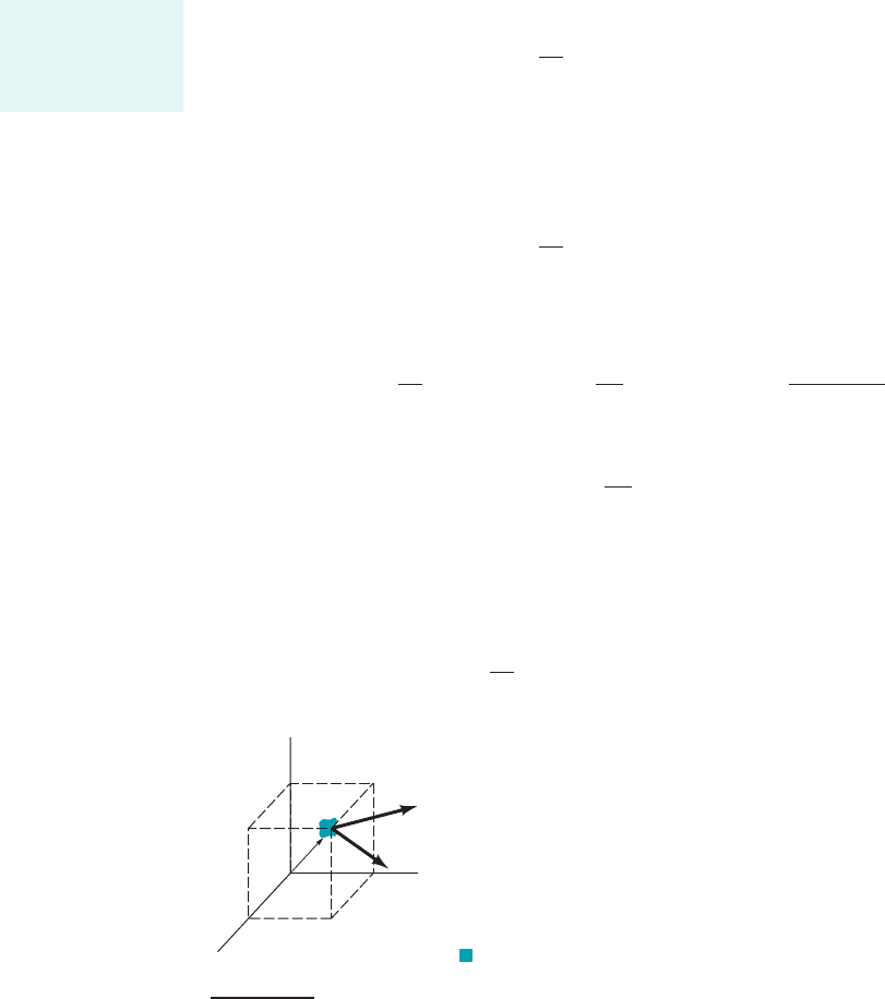
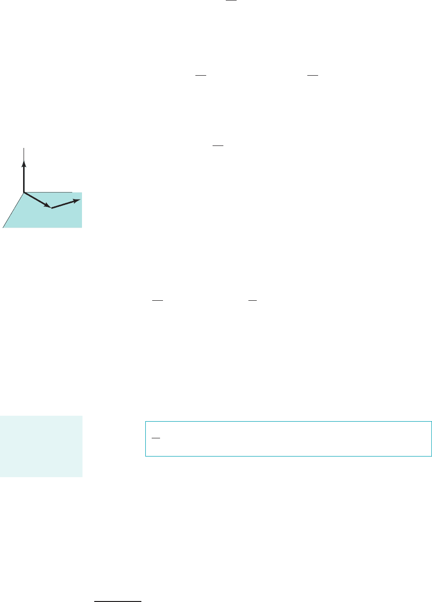
on the particle. If we form the moment of each side of Eq. 5.30 with respect to the origin of an
inertial coordinate system, we obtain
(5.31)
where r is the position vector from the origin of the inertial coordinate system to the fluid parti-
cle 1Fig. 5.32. We note that
(5.32)
and
(5.33)
Thus, since
(5.34)
by combining Eqs. 5.31, 5.32, 5.33, and 5.34, we obtain the expression
(5.35)
D
Dt
31r ⴛ V2r dV⫺ 4⫽ r ⴛ dF
particle
V ⴛ V ⫽ 0
Dr
Dt
⫽ V
D
Dt
31r ⴛ V2r dV⫺ 4⫽
Dr
Dt
ⴛ Vr d V⫺⫹r ⴛ
D1Vr d V⫺2
Dt
r ⴛ
D
Dt
1Vr d V⫺2⫽ r ⴛ dF
particle
dF
particle
dV⫺
r
D
Dt
1Vr d V⫺2⫽ dF
particle
5.2 Newton’s Second Law—The Linear Momentum and Moment-of-Momentum Equations 215
2
This section may be omitted, along with Sections 5.2.4 and 5.3.5, without loss of continuity in the text material. However, these sec-
tions are recommended for those interested in Chapter 12.
F I G U R E 5.3 Inertial coordinate system.
r
y
x
z
V
d
F
particle
The angular mo-
mentum equation is
derived from New-
ton’s second law.
JWCL068_ch05_187-262.qxd 9/23/08 9:59 AM Page 215
Equation 5.35 is valid for every particle of a system. For a system 1collection of fluid particles2,
we need to use the sum of both sides of Eq. 5.35 to obtain
(5.36)
where
(5.37)
We note that
(5.38)
since the sequential order of differentiation and integration can be reversed without consequence. 1Re-
call that the material derivative, denotes the time derivative following a given system; see
Section 4.2.1.2Thus, from Eqs. 5.36 and 5.38 we get
(5.39)
or
The sketch in the margin illustrates what torque, , is. For a control volume that is in-
stantaneously coincident with the system, the torques acting on the system and on the control vol-
ume contents will be identical:
(5.40)
Further, for the system and the contents of the coincident control volume that is fixed and nonde-
forming, the Reynolds transport theorem 1Eq. 4.192leads to
(5.41)
or
For a control volume that is fixed 1and therefore inertial2and nondeforming, we combine Eqs. 5.39,
5.40, and 5.41 to obtain the moment-of-momentum equation:
(5.42)
An important category of fluid mechanical problems that is readily solved with the help of
the moment-of-momentum equation 1Eq. 5.422involves machines that rotate or tend to rotate around
a single axis. Examples of these machines include rotary lawn sprinklers, ceiling fans, lawn mower
blades, wind turbines, turbochargers, and gas turbine engines. As a class, these devices are often
called turbomachines.
5.2.4 Application of the Moment-of-Momentum Equation
3
We simplify our use of Eq. 5.42 in several ways:
1. We assume that flows considered are one-dimensional 1uniform distributions of average ve-
locity at any section2.
0
0t
冮
cv
1r ⴛ V2r dV
冮
cs
1r ⴛ V2rV ⴢ nˆ dA
a
1r ⴛ F2
contents of the
control volume
time rate of change time rate of change net rate of flow
of the moment-of- of the moment-of- of the moment-of-
momentum of the momentum of the momentum through
system contents of the the control surface
control volume
D
Dt
冮
sys
1r ⴛ V2r dV
0
0t
冮
cv
1r ⴛ V2r dV
冮
cs
1r ⴛ V2rV ⴢ nˆ dA
a
1r ⴛ F2
sys
a
1r ⴛ F2
cv
T r F
the time rate of change of the
moment-of-momentum of the system
sum of external torques
acting on the system
D
Dt
冮
sys
1r ⴛ V2r d V
a
1r ⴛ F2
sys
D12
Dt,
D
Dt
冮
sys
1r ⴛ V2r dV
冮
sys
D
Dt
31r ⴛ V2r dV4
a
r ⴛ dF
particle
a
1r ⴛ F2
sys
冮
sys
D
Dt
31r ⴛ V2r dV4
a
1r ⴛ F2
sys
216 Chapter 5 ■ Finite Control Volume Analysis
T
T = r
×
F
F
r
y
x
z
For a system, the
rate of change of
moment-of-momen-
tum equals the net
torque.
3
This section may be omitted, along with Sections 5.2.3 and 5.3.5, without loss of continuity in the text material. However, these sec-
tions are recommended for those interested in Chapter 12.
JWCL068_ch05_187-262.qxd 9/23/08 10:00 AM Page 216