Pavlidis I. (ed.) Human-Computer Interaction
Подождите немного. Документ загружается.

Design Optimization of Pressure Sensing Floor for Multimodal Human-Computer Interaction
143
to read the pressure voltage signals. Three multiplexers are used for the row lines and three
for the column lines of the sensor matrix and each input line of the multiplexer is wired to a
single pressure sensor output. The microcontroller streams out the multiplexer selects
signals in a sequence to read the pressure values from sensor 1 to sensor 2016 one at a time.
A bunch of gain control operational amplifiers follows the multiplexers which performs the
necessary amplification and signal conditioning of the analog voltage. The outputs of the
operational amplifiers are fed to a high speed ADC0820 converter which coverts the sensed
analog voltage to 8 bit digital pressure value on the reception of the read/start- conversion
signal from the microcontroller. Digitized pressure data is transferred to RCM 3200 module
(Rabbit controller) through an input port after interrupt enabled handshaking signals with
the microcontroller. The RCM3200 module contains Rabbit 3000 processor running at 44.2
MHz and 10/100 Base-T Ethernet connectivity. It is worth mentioning again that the
multiplexer select signals, ADC read signal and rabbit interrupt signals are all generated by
the microcontroller which are the major control signals used to synchronize/sequence the
operation of the components on the hardware control board. Rabbit units are assigned
unique static IP addresses. The Rabbit module collects 8 bit digital pressure data of all 2016
sensors and assembles them to create a pressure packet pertaining to that mat. It attaches a
frame number at the end of each pressure packet and sends it out onto the network to the
host computer running the floor control software through an array of switches. The host
computer software listens to the IP addresses and port numbers to which the rabbit has been
programmed to send the pressure data thereby collecting pressure data for further
processing.
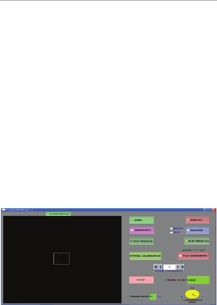
3.6 Floor Control and Visualization Engine (FCAVE)
Floor Control and Visualization Engine (FCAVE) software developed at the host computer
has an interactive graphical user interface with various control buttons and indicators (Fig.
4) and it is programmed to respond dynamically to user input. This software receives the
raw pressure data packet for each mat separately, assembles the data of all 96 mats, assigns
an incremental frame number and creates floor data frame which is ready for processing.
Fig. 4. Graphical user interface of Floor Control and Visualization Engine

Human-Computer Interaction
144
FCAVE software has two operating modes namely ‘live mode’ and ‘playback mode’. As the
name implies, real time data collection and processing is done in the ‘live mode’ whereas
offline data processing from a recorded pressure data file is usually done in the ‘playback
mode’. Furthermore playback can be done in synchronous and asynchronous ways.
Synchronous playback streams the recorded pressure data synchronous with the motion
capture playback stream. Asynchronous playback streams the recorded pressure data at the
desired frame rate without any synchronization with motion capture system. FCAVE also
offers various other controls like multicast pressure data to users on network, grayscale
display of pressure information, set noise filter value, perform mean shift tracking of
pressure clusters ,frame counter reset , record to file etc. FCAVE software development
paved way for enhanced user-friendliness (with a lot of features as shown in Fig. 4), efficient
data compression and mean shift tracking of active, disjoint pressure clusters in real time.
4. Hardware and Software Developments
This section mainly talks about hardware improvements done on AME Floor-II (Srinivasan,
P., 2006) and new software developments to result in AME Floor-III. AME Floor II
(Srinivasan, P., 2006) operated at frequency of 33 Hz and also suffered from significant
latency of 200 milliseconds. Latency experiments are done to measure and quantify the
latency along the data path and further optimizing them for latency reduction. Hardware
optimizations in AME Floor-III eventually lead to increased frame rate (33 Hz to 43 Hz) ,
reduced mean latency (200 ms to 25 ms) and improved real time performance over its
precursor AME Floor-II (Srinivasan, P., 2006).New software developments like data
compression and mean shift tracking have imparted context aware capabilities to the
system. This section elaborates on the hardware optimization techniques used to reduce
latency and increase frame rate and new software developments namely data compression
and mean shift.
4.1 Optimization of System Latency
Small latency is critical for real time sensing systems used in human-computer interaction
applications. Latency is defined as the time lag between the time instant of the true event
and the time instant the pressure data pertaining to the true event arrives at the end users on
a multicast network. The overall system latency is the sum of two components namely
intrinsic latency and extrinsic latency. Intrinsic latency is defined as the latency induced by
the sensor scanning process. Each sensing unit has a pressure mat with 2016 sensors and an
associated mat based controller for pressure data collection and signal conditioning. All
sensors are scanned sequentially from sensor 1 to sensor 2016 to read the pressure values.
There is an inherent delay for the scanning process to complete and pressure packet to be
produced. This delay is called as the intrinsic latency which is present due to lag in various
hardware components on the mat based controller. The microcontroller generates the sensor
scan signals and the scan routine incorporates all the hardware component delays. Thus the
total execution time of the microcontroller scan routine T
scan
determines the frame rate F (F =
1/ T
scan
) of the system. After a complete mat scan of 2016 sensors, the pressure data packet
for that mat is produced. Extrinsic latency is defined as the time taken for such a pressure
data packet to reach the end users on the multicast network and it accounts for the network
Design Optimization of Pressure Sensing Floor for Multimodal Human-Computer Interaction
145
transmission delay and FCAVE software delay. Due to sequential scanning process, the
intrinsic latency is direct function of the active sensor location given by a sensor address (An
active sensor would be one that has pressure applied on it and sensors are addressed
sequentially from 1 to 2016). A mathematical relationship is first established which gives an
expected range of the intrinsic latency values based on the system scan rate and active
sensor location. From this theoretical model, it becomes apparent on what latency
distribution to expect when pressure is applied on a particular sensor location and later
latency experiments are done to verify the same. The following section presents the
mathematical relationship between intrinsic latency, frame rate and active sensor location.
4.1.1 Theoretical approach – relationship of intrinsic latency, active sensor location
and frame rate
Let’s assume that the system is running at a frame rate F and the time taken for one
complete scan cycle of N sensors (N = 2016 in our case) is T
scan
. Pressure sensors applied
with active load are defined as active sensors. Let L be the address of such an active sensor.
The intrinsic latency related to this sensor at L needs to be determined. Let U be the address
of the sensor currently being scanned at the time instant when the pressure application
occurs on sensor L. Let X
L
and X
U
be time elapsed since the start of the scan until the sensor
L and sensor U are reached respectively by the scan routine, i.e.
X
L
= 1/N × L × T
scan
(1)
X
U
= 1/N × U × T
scan
(2)
According to the relationship between X
L
and X
U
, there are two different cases to be
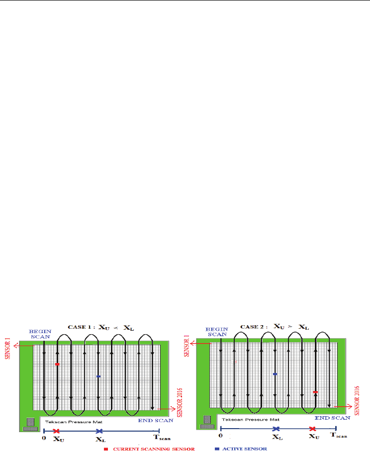
considered which are pictorially represented in Fig 5.
Fig. 5. Sequential mat scan process and depiction of Case 1 and Case 2
Case 1: X
U
≤ X
L
, pressure applied on sensel L is registered in the current scan cycle.
Case 2: X
U
> X
L
, pressure applied on sensel L is registered in the next scan cycle.
Hence, given L, the intrinsic latency
τ
caused by system scan is a function of X
U
,
Human-Computer Interaction
146
⎩
⎨
⎧
<<−
≤≤−
=
scanULUscan
LUUscan
U
TXXwhenXT
XXwhenXT
X
,2
0,
)(
τ
(3)
Since X
U
assumes a uniform distribution in [0, T
scan
] it can be easily shown that τ is
uniformed distributed in the range given below
LscanLscan
XTXT
−
≤
−
< 2
τ
(4)
Therefore, the mean intrinsic latency for the sensel at L is given by
Lscanm
XT
−
=
5.1
τ
(5)
Thus the mean intrinsic latency is a direct function of T
scan
and active sensor location X
L
.
Furthermore, since L can also be treated as a uniform random variable between 1 and N, the
mean average intrinsic latency of all sensels on a mat is given by
s
canLscanm
T}X{ET5.1}{E
=
−
=
τ
(6)
Equation 6 clearly reveals that the intrinsic latency depends on the frame rate F (1/T
scan
) and
active sensor location X
L
. As expected, the intrinsic latency decreases as the frame rate is
increased. Equation 6 implies that as the active sensor location becomes closer and closer
relative to the end of mat, the intrinsic latency decreases linearly. This can be justified by the
sequential nature of the scanning process. Latency experiments have been conducted
(explained in the following section) to verify the above statement and check the validity of
Equation 6.
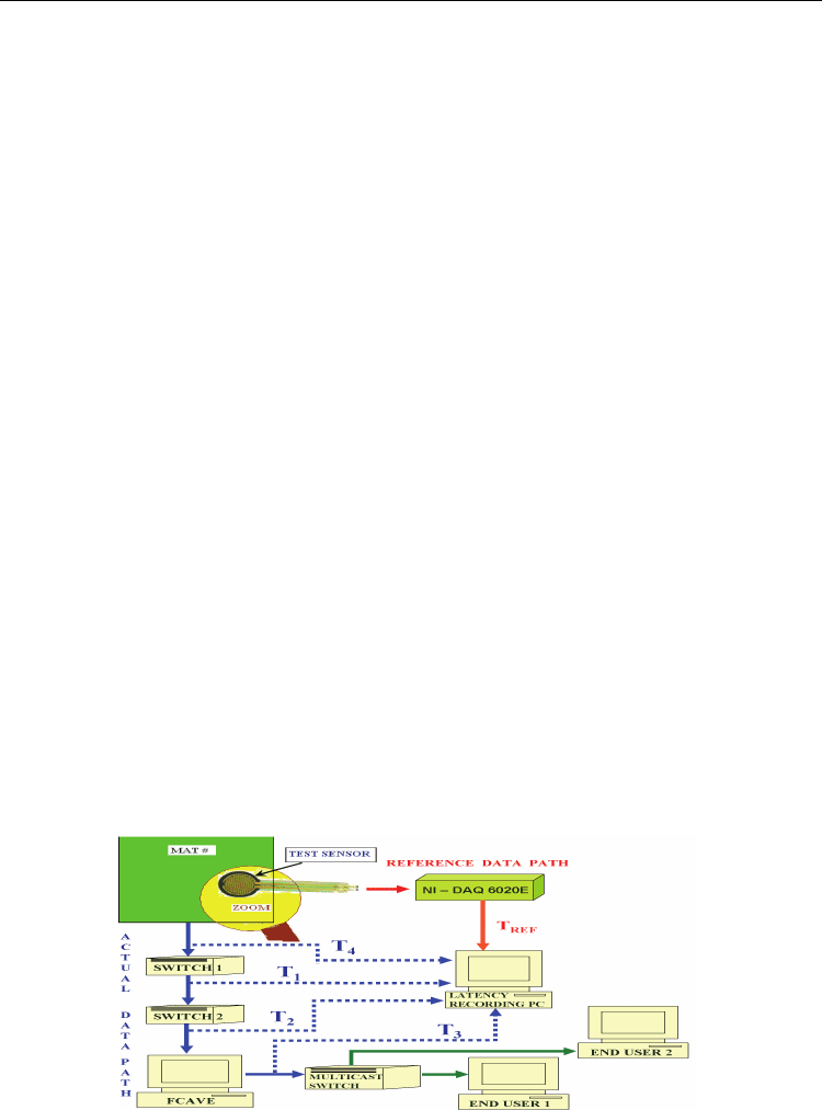
4.1.2 Experimental approach for measurements of system latency
The experimental set up shown in Fig 6 is used to measure both intrinsic and extrinsic
latency and thereby overall system latency.
Fig. 6. Experimental set up to measure the latency of each and every component along the
data path.

Design Optimization of Pressure Sensing Floor for Multimodal Human-Computer Interaction
147
In order to measure the latency, a time reference is required which gives the time
instant of the true event (e.g. pressure strike). The time of arrival of the actual data packet
pertaining to the true event is then recorded and the displacement in time between the time
reference and arrival time gives the measure of latency. A single physical test sensor (shown
under zoom lens in Fig 6), National Instruments data acquisition hardware (NI-DAQ 6020E)
and Labview application are used to get the time reference of the true event. The test sensor
is placed directly above the sensor on the mat on which the pressure is going to be applied
(active sensor). The Labview application is programmed to read the incoming data from two
input ports namely reference data port and actual data port. The test sensor output feeds to
the NI-DAQ hardware and in turn to the reference data port of the Labview software
application to create the reference data path. The components in the reference data path are
chosen to be relatively fast and responsive to give a solid reference for accurate latency
measurements. Actual data path is the normal data flow through the switches and floor
control software given by the system architecture. Actual data port of the Labview software
is connected to fetch the data anywhere along the actual data path as shown in Fig 6.
Pressure applied by a swift strike on the test sensor is the event used in the experiment.
Sensor beneath the test sensor suffers the event at the same instant of time as that of the test
sensor and hence the test sensor can be used a reference. When an event occurs, two
different channels (reference data path and actual data path) carry information about the
same event to the Labview software application. Labview software reads the data from the
test sensor arriving at the reference data port and records the arrival time. Under the
assumption that the transmission delays along the reference data path are at negligible
levels, the reference time stamp gives the time instant of the true event. Also the active
sensor on the pressure mat transmits the event through the actual data path to the actual
data port of the Labview application. Labview records the arrival time of the actual data
packet as well. The time displacement between the actual data arrival time and reference
data arrival time is computed by the Labview application as a true value of latency.
Different read out points namely (T
1
, T
2
, T
3
, T
4
) are taken to measure and quantify
the latency at each and every point along the data path. Intrinsic latency is obtained from T
4
and T
REF
values. Extrinsic latency is mainly caused by the various components in the data
path like the two network switches and host computer running the floor control software.
T
1
,T
2
and T
3
measurements are used to quantify the latency added by switch 1, switch 2 and
floor control software respectively using the formulas given below.
T
INL
= T
4
- T
REF
(7)
LATENCY
SW 1
= T
1
– T
INL
– T
REF
(8)
LATENCY
SW 2
= T
2
– T
1
(9)
LATENCY
FCAVE
= T
3
– T
2
(10)
Extrinsic latency measurements done on AME Floor-II (Srinivasan, P., 2006)
revealed a major contribution of 167 milliseconds (LATENCY
FCAVE
) from floor control
software and negligible additions by the network switches (LATENCY
SW1
& LATENCY
SW2
).
Human-Computer Interaction
148
The floor computer was then upgraded to dual processor, dual core and multithreading
techniques were used to improve the real time performance of floor control software and
reduce extrinsic latency to negligible levels in AME Floor-III.
Having reduced the extrinsic latency to negligible levels, focus is shifted to intrinsic
latency reduction. This experimental set up is further used to get empirical measurements
of intrinsic latency T
INL
and validate the mathematical model derived in section 4.1.1.
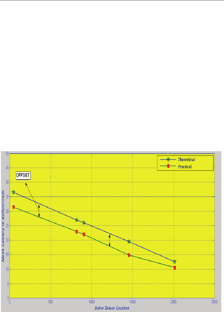
Pressure is applied on a set of fixed sensor locations on the mat and the mean system latency
is computed for over 100 trials for the floor system running at 40 Hz. Equation 6 gives the
theoretical estimate of the mean latency given the active sensor location and frame rate. Fig
7 shows the correlation between the mean latency values computed from theoretical and
practical data sets when the system is running at 40Hz. The offset between theoretical and
practical values is mainly due to the DAQ polling frequency by Labview application. It is
found that Labview application polls the data acquisition card (NI-DAQ 6020E) at 5
millisecond intervals (DAQ polling error) on an average. Hence the time reference T
REF
is
delayed from the true value by a time period t, where t is a random variable (0 ≤ t ≤ DAQ
polling error).This explains why the practical value of latency is less than the theoretical
value by an offset ‘t’. In other words the offset or mean error between the theoretical and
practical data sets should always be less than or equal to the DAQ polling error which is
proved by means of Table 2.
Fig. 7. Plot of mean latency (ms) vs. active sensor location for theoretical and practical data.

Design Optimization of Pressure Sensing Floor for Multimodal Human-Computer Interaction
149
Active Sensor
Location (0-2015)
Theoretical
Mean
Practical Mean
( > 75 Trials)
Mean Error
DAQ
Polling
error
48 36. 5 31. 36 5.14 6
815 27 23 4 4
905 26 22 4 5
1455 19. 5 14. 88 4.62 5
2015 12. 5 10. 53 1.97 4
Table 2. Mean error between theoretical and practical data sets for different sensor locations
Equation 6 states that we can minimize intrinsic latency by minimizing T
scan
, or
equivalently maximizing the frame rate (F = 1/T
scan
). Hence efforts were invested to increase
the frame rate and reduce intrinsic latency which is described in section 4.2.
4.2 Maximization of Frame Rate
Frame rate of floor system is determined by the speed of hardware components on the
hardware control board. Every hardware component has certain delay or lag associated
with it. The microcontroller scan routine incorporates all the hardware component delays
and accordingly generates the control signals. The sum of all hardware component delays
gives minimum T
scan
required whose reciprocal gives the maximum achievable frame
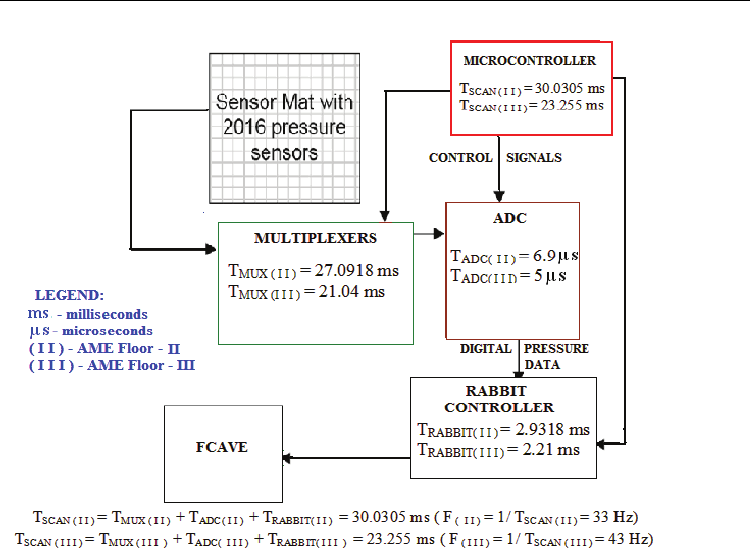
rate.Fig 8 shows the block diagram of floor hardware (Srinivasan, P., 2006) annotated with
delay values for each hardware component explaining how we had achieved a maximum
frame rate of 43 Hz in AME Floor- III from an old value of 33 Hz in AME Floor-II prototype
(Srinivasan, P., 2006). It is important to note that suffix (II) on Fig 8 refers to AME Floor-II
whereas suffix (III) refers to AME Floor-III system. The block diagram quantifies the time
savings obtained on each hardware component in the current system relative to AME Floor-
II. These time savings and hence increase in frame rate are obtained by doing a more refined
timing analysis on each hardware component to determine their operational delay and
accordingly generating the timing and control signals from the microcontroller. Section 4.2.1
enumerates the technique used to increase the frame rate from 33 Hz to 43 Hz.
Human-Computer Interaction
150
Fig. 8. Block diagram of Floor hardware annotated with hardware component delays
4.2.1 Frame rate increase technique
It is apparent from Fig 8 that the time savings obtained in the A/D converter, multiplexer
and rabbit controller lead to an overall increase in frame rate from 33 Hz to 43 Hz. The
operational delay of the A/D converter and rabbit controllers are determined by trial and
error procedure. Repeated iterations are done with different delay values (for A/D and
rabbit) in the microcontroller routine and the least delay for correct operation is then
determined. Major time saving is obtained in the multiplexers by non-uniform multiplexing
technique. It is important to note that the time taken for each sensor to be scanned and
pressure value to be read is not uniform for all 2016 sensors on the pressure sensing mat.
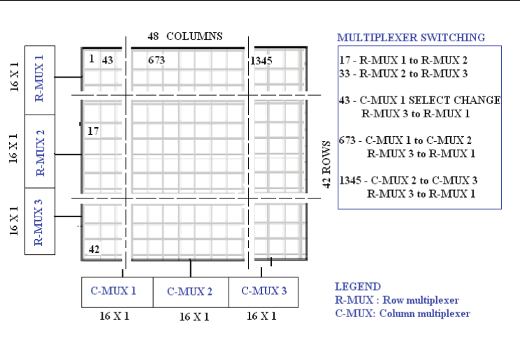
The reason behind the above statement can be explained with the aid of Fig 9. The floor
control hardware includes three 16 x 1 row multiplexers and three 16 x 1 column
multiplexers. Each input line of the multiplexer is wired to single sensor output. The
microcontroller generates the multiplexer enable signal to enable a particular row and
column multiplexer. Soon afterwards, the multiplexer select signals are also sent out by the
microcontroller to read a particular input line. Additional instructions are required in the
microcontroller scan routine when there is a switch from one multiplexer to another. The
sensors wired to the first input line of multiplexer accounts for such a switch thereby taking
more time to complete. For example, sensor 17 on the mat requires a switch from row mux-1
to row mux-2 which is achieved by additional instructions and hence longer completion
time. Sensor 1345 takes even longer time to complete because it requires two switches
namely column mux-2 to column mux-3 and row mux-3 to row mux-1.
Design Optimization of Pressure Sensing Floor for Multimodal Human-Computer Interaction
151
Fig. 9. The arrangement of multiplexers for a pressure sensing mat and sensors that require
longer scanning time due to multiplexer switching.
AME Floor-II (Srinivasan, P., 2006) resorted to a uniform multiplexing technique whereby
the time taken to scan each sensor was made uniform throughout the pressure sensing mat.
The worst case or longest sensor scanning delay was determined and all sensors were
scanned uniformly with that delay value. This was achieved by incorporating additional
delays even for sensors that could have finished scanning in lesser time. In AME Floor-III all
these extra delays were removed and the multiplexing is made non-uniform. Currently,
each sensor is scanned at the fastest rate possible which eventually leads to significant
savings in multiplexer to finish operation and thereby increase in frame rate.
4.3 Data Compression
Each pressure mat has 2016 sensors and each sensor in turn sends one byte of pressure data
at 43 Hz. Thus each mat data packet size adds to 2017 bytes which includes 2016 bytes of
pressure data and one byte of frame number. The data volume from the entire floor
comprising of 96 mats running at 43 Hz is a whopping 8.4 MB/sec. Usually, except a small
area where the subject is in contact with the pressure sensing floor, most of the sensors do
not have any load acting on them. Consequently a large proportion of the sensor data are
null values of pressure or noise serving no interest to applications. Also there has been slight
random noise observed in few sensors because of the nature of the sensing material which
reports small values of pressure. Hence a simple but elegant compression algorithm is
implemented by the floor control software to filter out all pressure values below the chosen
noise threshold and pack only “active” sensor values and their addresses (location on floor
system matrix) to be sent out to the end users on the network. Compression ratio as high as

Human-Computer Interaction
152
0.9 is observed under normal case with five subjects which proves significant data volume
reduction on the network.
It is known that compressed data packet comprise of only active sensor values and their
address whereas the uncompressed data packet comprise of all sensor values (arranged in a
sequence) and no address information since its address is implied by its location in the data
packet. Thus the compression algorithm adds an additional overhead of sensor address
which works well for low user activity with less active sensors. However as the user activity
on the floor increase or when large numbers of sensors are active, the packet size also grows
and a point is reached when compressed data volume exceeds uncompressed data volume.
It is determined that this breakeven point is generally high and beyond bounds for normal
usage. Hence the algorithm works well for most of the situations.
4.4 Mean Shift Tracking of Pressure Clusters
Context awareness is the vital part of any smart environment. Perceiving context means
sensing the state of the environment and users and it can be done with regard to a person or
an activity. This may involve a variety of tasks such as person recognition, person location
tracking, activity detection, activity recognition, activity learning etc. The primary step to
accomplish the above tasks is to develop an efficient tracking procedure that shall ascertain
the person location on the floor and also shift in the pressure gradient. The latter may lead
to the study of various pressure patterns tied to each and every user activity. A mean shift
algorithm is used to achieve the above mentioned goal. Mean shift is a simple iterative
procedure that shifts each pressure data point to the average of the pressure data points in
the neighbourhood.
4.4.1 Mean shift: an introduction
Mean shift is the process of repetitively shifting the centre t to the sample mean. The sample
mean of samples S under a kernel K(x) centred at t, with sample weights w(s), can be found
using this equation:
∑
∑
∈
∈
−
−
≡
Ss
Ss
swtsK
sswtsK
tm
)()(
)()(
)(
(11)
where m(t) is the new sample mean (Cheng., 1995). It’s proven (Comaniciu et al., 2000) that
if the kernel K(x) has a convex and monotonically decreasing profile k(||x||²), then the
centre t will converge onto a single point. The kernel used in our tracking algorithm is the
truncated Gaussian kernel which is the combination of the flat kernel and Gaussian kernel.
The truncated Gaussian kernel is given by
⎪
⎩
⎪
⎨
⎧
>
≤
=
−
λ
λ
β
βλ
xif
xife
xGF
x
0
))((
2
(12)
where λ is the radius of the Gaussian kernel and β is the Gaussian kernel coefficient.