Pecharsky V.K., Zavalij P.Y. Fundamentals of Powder Diffraction and Structural Characterization of Materials
Подождите немного. Документ загружается.

Chapter
3
EXPERIMENTAL TECHNIQUES
3.1
Introduction
The powder diffraction experiment is the cornerstone of a truly basic
materials characterization technique
-
diffraction analysis'
-
and it has been
used for many decades with exceptional success to provide accurate
information about the structure of materials. Although powder data usually
lack the three-dimensionality of a diffraction image, the fundamental nature
of the method is easily appreciated from the fact that each powder diffraction
pattern represents a one-dimensional snapshot of the three-dimensional
reciprocal lattice of a
cry~tal.~ The quality of the powder diffraction pattern
is usually limited by the nature and the energy of the available radiation, by
the resolution of the instrument, and by the physical and chemical conditions
of the specimen. Since many materials can only be prepared in a
polycrystalline form, the powder diffraction experiment becomes the only
realistic option for a reliable determination of the crystal
structure of such
materials.
Powder diffraction data are customarily recorded in virtually the simplest
possible fashion, where the scattered intensity is measured as a function of a
single independent variable
-
the Bragg angle. What makes the powder
diffraction experiment so powerful is that different structural features of a
material have different effects on various parameters of its powder
diffraction pattern. For example, the presence of a crystalline phase is
manifested as a set of discrete intensity maxima
-
the Bragg reflections
-
'
Fundamentals of diffraction analysis were considered in Chapter
2.
Imaging of the reciprocal lattice in three dimensions is easily doable in a single crystal
diffraction experiment.
262
Chapter 3
each with a specific intensity and location. When atomic parameters, e.g.
coordinates of atoms in the unit cell or populations of different sites in the
lattice of the crystalline phase are altered, this change affects relative
intensities and/or positions of the Bragg peaks that correspond to this phase.
When the changes are microscopic, e.g. when the grain size is reduced below
a certain limit or when the material has been strained or deformed, then the
shapes of Bragg peaks become affected in addition to their intensities and
positions. Hence, much of the structuial information about the material is
embedded into its powder diffraction pattern, and when experimental data
are properly collected and processed, a great deal of details about a
material's structure at different length scales, its phase and chemical
compositions can be established.
3.2
Brief history of the powder diffraction method
The x-ray powder diffraction method dates back to Debye and Scherrer'
who were the first to observe diffraction from LiF powder and succeeded in
solving its crystal structure. Later, Hull2 suggested and Hanawalt, Rinn and
Freve13 formalized the approach enabling one to identify crystalline
substances based on their powder diffraction patterns. Since that time the
powder diffraction method has enjoyed enormous respect in both academia
and industry as a technique that allows one to readily identify the substance
both in a pure form and in a mixture in addition to its ability to provide
information about the crystal structure (or the absence of crystallinity) of an
unknown powder.
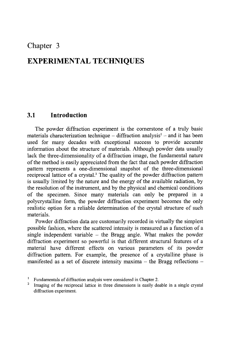
In
the early days of the method, powder diffraction data were recorded on
x-ray film in a variety of cameras. Using film, the resulting diffraction
pattern is usually observed as a series of elliptically distorted narrow
concentric ring segments (Figure 3.
I),
where each ring corresponds to one or
more Bragg peaks. Multiple Bragg peaks may be convoluted into a poorly
resolved or completely unresolved single ring due to the limitations imposed
by the one-dimensionality of the technique and by the resolution of both the
film and the instrument, e.g. the Debye-Scherrer camera (Figure 3.2).
From the locations of Debye rings on the film plus their varying intensity
(degree of darkening), it is possible to identify the material and to establish
its crystal structure. Given the analogue nature of the film, it is nearly as
easy to grasp the overall "structure" of the diffraction pattern, as it is
'
P. Debye, and P. Scherrer, Interferenzen an regellos orientierten Teilchen in Rontgenlight,
Phys.
Z.
17,277
(1916).
A.W. Hull, A new method of chemical analysis,
J.
Am. Chem. Soc.
41,
1168 (1919).
J.D.
Hanawalt, H.W. Rinn, and
L.K.
Frevel, Chemical analysis by x-ray diffraction, Ind.
Eng. Chem. Anal.
10,457
(1938).
Experimental techniques
263
difficult to convert it into a digital format, and considerable effort is usually
required
to
measure both the Bragg angles and diffracted intensities with
high precision.
Bragg angle,
8
(from 0
to
90•‹)
.I
Figure
3.1.
Film with the x-ray diffraction pattern of the polycrystalline LUAU needle
recorded in a Debye-Schemer camera using Cu
Ka
radiation. Bragg peaks are observed as
concentric ring segments with varying darkness. Spottiness of some rings, clearly visible at
low Bragg angles in the expanded view, indicates insufficient number of grains in the
irradiated volume of the sample, which was achieved by annealing the needle at
900•‹C
to
promote grain growth. (Film courtesy of Dr.
K.A.
Gschneidner, Jr.)
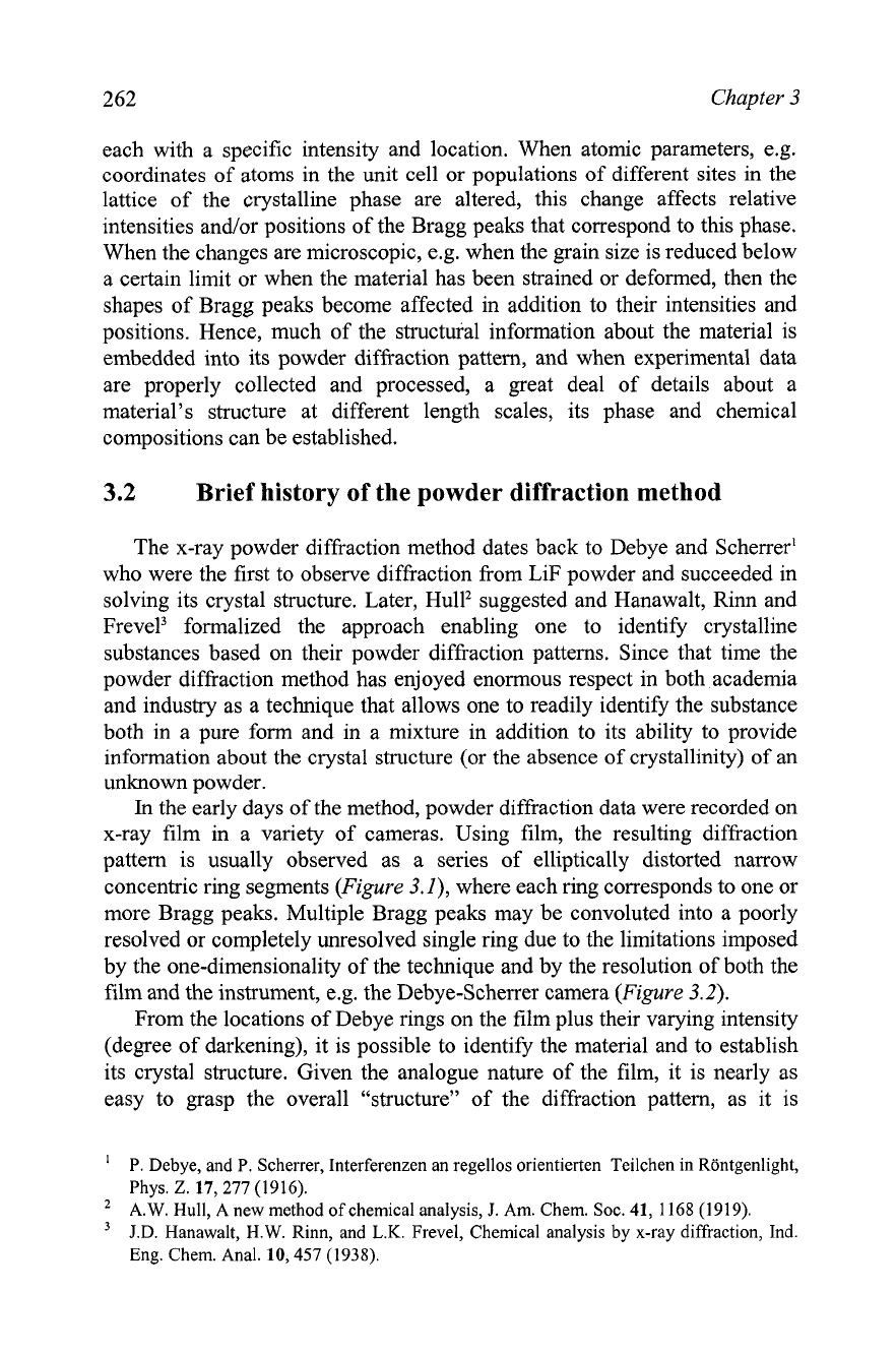
Figure
3.2.
Debye-Scherrer camera without a cover showing cylindrical sample, collimator,
incident beam trap, and the location of the x-ray film.
264
Chapter
3
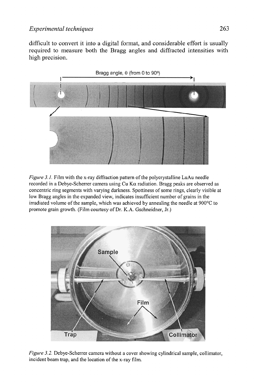
Cameras for x-ray powder diffraction are relatively simple but precise
optical instruments, and require dark room for loading and developing x-ray
film. Debye-Schemer cameras (Figure
3.2)
were in the most common use in
crystallographic laboratories in the past, and many are still on display today.
Debye-Schemer cameras are exceptionally reliable and nearly maintenance-
free devices. When the camera has been loaded with both the sample and the
film, the entire diffraction pattern was recorded all at once, in a single
exposure (Figure
3.3).
The typical time to register one powder diffraction
pattern on film is from
1
to
3
hours depending on the radius of the camera,
the crystallinity of the specimen and the sensitivity of the film.'
Powder diffraction data today are almost exclusively collected using
much more sophisticated analytical instruments
-
powder diffractometers
(Figure
3.4).
A
powder diffractometer furnishes fully digitized experimental
data in the form of diffracted intensity as a numerical function of Bragg
angle (see Figure
3.5).
By their nature, powder diffractometer data are
exceptionally well suited for computerized processing. They usually provide
accurate information about the structure of materials, especially when
coupled with Rietveld analysis: in which subtle anomalies of Bragg peak
shapes are used in addition to the integrated intensities of Bragg reflections
to extract important information about structural details.
Figure
3.3.
Two Debye-Schemer cameras with covers, which have been loaded with x-ray
film and installed on the x-ray generator, ready for collecting powder diffraction data.
It may take as much as 12 to 24 hours, especially when using low energy x-rays (e.g. Cr
Ka
radiation) in combination with a highly absorbing powder and a large camera radius.
The Rietveld method will be considered in Chapter
7.
Experimental techniques
265
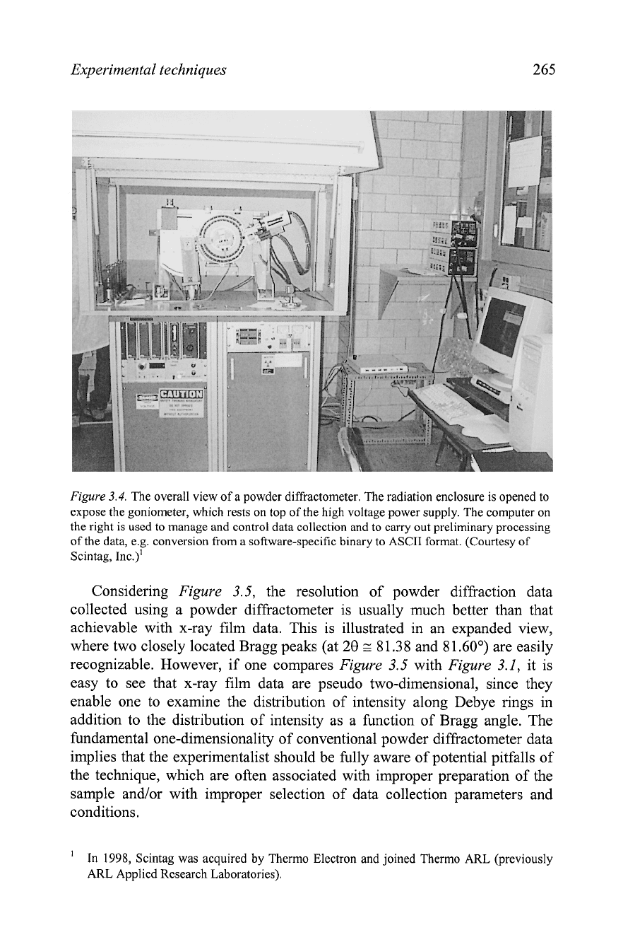
Figure
3.4.
The overall view of a powder diffractometer. The radiation enclosure is opened to
expose the goniometer, which rests on top of the high voltage power supply. The computer on
the right is used to manage and control data collection and to carry out preliminary processing
of the data, e.g. conversion from a software-specific binary to ASCII format. (Courtesy of
Scintag, ~nc.)'
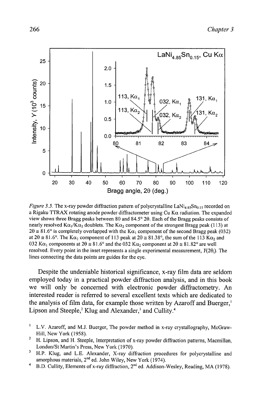
Considering
Figure
3.5, the resolution of powder diffraction data
collected using a powder diffractometer is usually much better than that
achievable with x-ray film data. This is illustrated in an expanded view,
where two closely located Bragg peaks (at 28
z
81.38
and 8
1
.60•‹) are easily
recognizable. However, if one compares
Figure
3.5 with
Figure
3.1, it is
easy to see that x-ray film data are pseudo two-dimensional, since they
enable one to examine the distribution of intensity along Debye rings in
addition to the distribution of intensity as a function of Bragg angle. The
fundamental one-dimensionality of conventional powder diffractometer data
implies that the experimentalist should be fully aware of potential pitfalls of
the technique, which are often associated with improper preparation of the
sample and/or with improper selection of data collection parameters and
conditions.
'
In
1998,
Scintag was acquired by Thermo Electron and joined Thermo ARL (previously
ARL Applied Research Laboratories).
Chapter
3
I
I I I I I I
I I I I
20 30 40 50 60 70
80
90 100 110 120
Bragg angle,
28
(deg.)
Figure
3.5.
The x-ray powder diffraction pattern of polycrystalline LaNi4,8SSno,lS recorded on
a Rigaku TTRAX rotating anode powder diffractometer using Cu Ka radiation. The expanded
view shows three Bragg peaks between 80 and 84.5O 20. Each of the Bragg peaks consists of
nearly resolved KallKa2 doublets. The Ka2 component of the strongest Bragg peak (1 13) at
20
z
81.6" is completely overlapped with the Ka, component of the second Bragg peak (032)
at 20
s
81.6'. The Ka, component of 113 peak at 28
a
81.38", the sum of the 113 Ka2 and
032 Ka, components at 20
E
81.6" and the 032
Ka2
component at 20
E
81.82" are well
resolved. Every point in the inset represents a single experimental measurement, Y(20;). The
lines connecting the data points are guides for the eye.
Despite the undeniable historical significance, x-ray film data are seldom
employed today in a practical powder diffraction analysis, and in this book
we will only be concerned with electronic powder diffractometry.
An
interested reader is referred to several excellent texts which are dedicated to
the analysis of film data, for example those written by Azaroff and Buerger,l
Lipson and Stee~le,~ Klug and Ale~ander,~ and C~llity.~
L.V. Azaroff, and M.J. Buerger, The powder method in x-ray crystallography, McGraw-
Hill, New York (1958).
2
H. Lipson, and H. Steeple, Interpretation of x-ray powder diffraction patterns, Macmillan,
LondonISt Martin's Press, New York (1970).
H.P. Klug, and L.E. Alexander, X-ray diffraction procedures for polycrystalline and
amorphous materials,
2"d ed. John Wiley, New York (1974).
B.D. Cullity, Elements of x-ray diffraction, 2"* ed. Addison-Wesley, Reading, MA (1978).
Experimental techniques
267
The last few decades of the 2oth century transformed the powder
diffraction experiment from a technique familiar to a few into one of the
most broadly practicable analytical diffraction experiments, particularly
because of the availability of a much greater variety of sources of radiation
-
sealed and rotating anode x-ray tubes were supplemented by intense neutron
and brilliant synchrotron radiation sources. Without a doubt, the accessibility
of both neutron and synchrotron radiation sources started a revolution in
powder diffraction, especially with respect to previously unimaginable kinds
of information that can be extracted from a one-dimensional projection of
the three-dimensional reciprocal lattice of a crystal. Yet powder diffraction
fundamentals remain the same, no matter what is the brilliancy of the source
of particles or x-ray photons employed to produce diffraction peaks, and
how basic or how advanced is the method used to record the powder
diffraction data.
The conventional analytical powder diffractometer has been and hitherto
continues to be a workhorse for thousands of researchers, both mature and
those who are just at the beginning of their careers in science and industry.
Appropriately, this chapter is illustrated by many examples obtained using
standard analytical instruments. Needless to say that when a more advanced
radiation source is used to study the phenomenon of powder diffraction from
the same quality specimen, this will only result in a better
(i.e. more
accurate) set of experimental data.
3.3
Powder diffractometers
As mentioned in the previous section, beginning approximately in the
1970's, powder cameras and x-ray film were steadily replaced by automated
analytical instruments
-
powder diffractometers. Despite a large variety of
both commercial and one-of-a-kind
apparati
found in analytical laboratories
around the world, nearly all of them have many common characteristics
dictated by the properties of x-rays.' Since standard x-ray tubes produce
divergent beams, most of the high resolution powder diffractometers use
self-focusing geometries, which improve both the diffracted intensity and the
resolution of the instrument. This is usually achieved by highly precise x-ray
optics, which is incorporated into the critical part of powder diffractometer
hardware
-
the goniometer (or goniostat), and by a thorough alignment of
the latter.
'
In this book we are predominantly concerned with the so-called Bragg-Brentano focusing
geometry. Other types of geometries, e.g. those using Seemann-Bohlin and Guinier
geometries, will not be considered here because their use in the determination and
refinement of crystal structure from powder diffraction data is limited, when compared to
the Bragg-Brentano technique.
268
Chapter
3
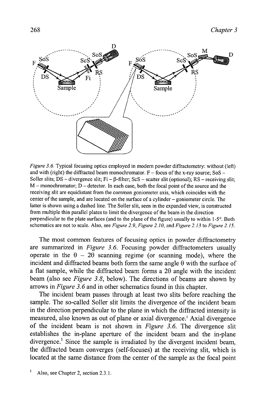
Figure
3.6.
Typical focusing optics employed in modem powder diffractometry: without (left)
and with (right) the diffracted beam monochromator. F
-
focus of the x-ray source; SoS
-
Soller slits; DS
-
divergence slit; Fi
-
0-filter; ScS
-
scatter slit (optional); RS
-
receiving slit;
M
-
monochromator;
D
-detector. In each case, both the focal point of the source and the
receiving slit are equidistant from the common goniometer axis, which coincides with the
center of the sample, and are located on the surface of a cylinder
-
goniometer circle. The
latter is shown using a dashed line. The Soller slit, seen in the expanded view, is constructed
from multiple thin parallel plates to limit the divergence of the beam in the direction
perpendicular to the plate surfaces (and to the plane of the figure) usually to within
1-5'.
Both
schematics are not to scale. Also, see
Figure 2.9, Figure 2.10,
and
Figure
2.13
to
Figure 2.15.
The most common features of focusing optics in powder diffractometry
are summarized in
Figure
3.6. Focusing powder diffractometers usually
operate in the 8
-
28 scanning regime (or scanning mode), where the
incident and diffracted beams both form the same angle 8 with the surface of
a flat sample, while the diffracted beam forms a 28 angle with the incident
beam (also see
Figure
3.8, below). The directions of beams are shown by
arrows in
Figure
3.6 and in other schematics found in this chapter.
The incident beam passes through at least two slits before reaching the
sample. The so-called Soller slit limits the divergence of the incident beam
in the direction perpendicular to the plane in which the diffracted intensity is
measured, also known as out of plane or axial divergence.' Axial divergence
of the incident beam is not shown in
Figure
3.6. The divergence slit
establishes the in-plane aperture of the incident beam and the in-plane
divergence.' Since the sample is irradiated by the divergent incident beam,
the diffracted beam converges (self-focuses) at the receiving slit, which is
located at the same distance from the center of the sample as the focal point
'
Also, see Chapter
2,
section
2.3.1.
Experimental techniques
269
of the source. These two distances remain constant at any Bragg angle, and
both the focal point of the x-ray source and the receiving slit of the detector
are located on the circumference of an imaginary circle (cylinder), which is
known as the goniometer circle. The radius of the goniometer cylinder is
identical to the goniometer radius.
The diffracted beam passes through the second Soller slit before reaching
the detector when no monochromator is employed (Figure 3.6, left), or it is
reflected in a crystal-monochromator on its path to the detector (Figure 3.6,
right).
An
additional scatter slit, located before the receiving slit, can be
employed to reduce the background. The Soller slit on the diffracted beam
side can be placed between the scatter and receiving slits.
The diffracted beam is monochromatized using a P-filter (Figure 3.6,
left) or a crystal monochromator (Figure 3.6, right). Quite rarely the
monochromatization geometries shown in Figure 3.6 are reversed,
i.e. the
incident beam rather than the diffracted beam is monochromatized using
either a P-filter or a crystal monochromator. The monochromatization of the
diffracted beam is advantageous in that fluorescent x-rays (which may be
quite intense in some combinations of samples and photon energies, e.g. see
Figure 3.16, below) can be suppressed, thus reducing the background.
The common optical features described above may be realized in
different ways in the actual hardware design of a powder diffractometer
goniostats and thus, goniometers differ from one another by:
1. The orientation of both the goniometer axis and specimen surface (or
specimen axis) with respect to the horizon, i.e. they may be located in a
vertical or horizontal plane.
2.
Diffraction geometry
-
reflection or transmission
-
when scattered
intensity is registered after the reflection from or after the transmission
through the sample, respectively.
3.
Motions of the goniometer arms, i.e. according to which arms of the
goniometer are movable and which are stationary.
3.3.1
Principles of goniometer design in powder diffractometry
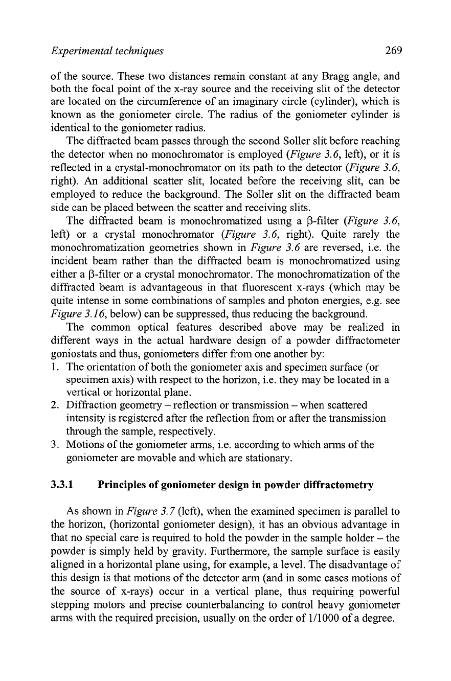
As shown in Figure
3.7
(left), when the examined specimen is parallel to
the horizon, (horizontal goniometer design), it has an obvious advantage in
that no special care is required to hold the powder in the sample holder
-
the
powder is simply held by gravity. Furthermore, the sample surface is easily
aligned in a horizontal plane using, for example, a level. The disadvantage of
this design is that motions of the detector arm (and in some cases motions of
the source of x-rays) occur in a vertical plane, thus requiring powerful
stepping motors and precise counterbalancing to control heavy goniometer
arms with the required precision, usually on the order of 111000 of a degree.
270
Source
Detector
Chapter 3
Source
I
Detector
0
Figure 3.7.
Horizontal (left) and vertical (right) orientations of a flat sample. The location of
the goniometer axis is shown using a dash-double dotted line with small filled circles at the
ends. The dashed line indicates the location of the optical axis, which is the line connecting
the focus of the x-ray tube, the receiving slit and the sample surface in the reflection
geometry, or the sample center in the transmission geometry at
0
=
20
=
0".
On the other hand, the simplicity of the goniometer arms motion in a
horizontal plane, when the sample is located in a vertical plane (Figure 3.7,
right), is offset by the need of more complicated sample preparation to
ensure that it stays in place and does not fall of. This is usually achieved by
side packing the sample holder or by mixing a powder with a binder
(e.g., x-
ray amorphous and chemically inert petroleum jelly, oil, grease or varnish),
which typically increase preferred orientation or background, respectively
(see section
3.5
for more details on sample preparation).
The orientation of the sample usually establishes the orientation of the
goniometer axis, i.e. the axis around which both the detector and sample (or
both the detector and x-ray source) rotate in a synchronized fashion during
8-28
or
8-8
data collection.
A
horizontal sample orientation implies that the
goniometer axis is located in the horizontal plane, and a vertical sample
orientation makes the goniometer axis vertical, as depicted in Figure 3.7.
The reflection geometry takes full advantage of the focusing of the
diffracted beam as shown in Figure 3.8. This geometry is commonly known
as the Bragg-Brentano focusing method and it results in both high resolution
and high diffracted intensity. Furthermore, the Bragg-Brentano
experimental setup translates into a relatively straightforward sample
preparation, and when this diffraction geometry is coupled with the
horizontal goniometer axis, the sample can be in a liquid state.
A disadvantage of the Bragg-Brentano geometry, in addition to being
susceptible to preferred orientation, is in that it may be difficult to prepare a
sample of an adequate thickness to ensure that it is completely opaque to x-
rays. This is especially true when examining weakly absorbing materials,
e.g., molecular compounds containing only light elements
(C,
N,
0, and
H).'
Low absorption may affect positions of Bragg peaks due to transparency shift (Chapter
2,
section
2.8.2)
and/or systematically distort scattered intensity (Chapter
2,
section
2.10.5).