Power electronic handbook
Подождите немного. Документ загружается.

876 M. F. Rahman et al.
Substituting the expressions for i
qr
and i
dr
into Eqs. (33.35)
and (33.36),
λ
qs
=
L
s
−
L
2
m
L
r
i
qs
+
L
m
L
r
λ
qr
(33.54)
λ
ds
=
L
s
−
L
2
m
L
r
i
ds
+
L
m
L
r
λ
dr
(33.55)
Substituting λ
qs
and λ
ds
from Eqs. (33.54) and (33.55) into
the torque equation of Eq. (33.41),
T =
3P
2
L
m
L
r
λ
dr
i
qs
−λ
qr
i
ds
=
3P
2
L
m
L
r
ˆ
λ
r
i
qs
(33.56)
It is clear from Eq. (33.53) that the rotor flux
ˆ
λ
dr
is
determined by i
ds
, subject to a time delay T
r
which is the
rotor time constant (L
r
/R
r
). The Current i
qs
, according to
Eq. (33.56), controls the developed torque T without delay.
Currents i
ds
and i
qs
are orthogonal to each other and are called
the flux- and torque-producing currents, respectively. This
correspondence between the flux- and torque-producing cur-
rents is subject to maintaining the conditions in Eqs. (33.50)
and (33.51). Normally, i
ds
would remain fixed for operation
up to the base speed. Thereafter, it is reduced in order to
weaken the rotor flux so that the motor may be driven with a
constant-power-like characteristic.
Based on how the rotor flux is detected and regulated, two
methods of control are available. One is the more popular
indirect rotor flux oriented control (IFOC) method and the
other is the direct vector control method; both are described
hereafter.
P
W
M
I
N
V
+
−
+
+
i
∗
qs
i
∗
ds
i
qs
i
ds
i
qs
+
∫
+
M
E
Speed
Controller
Current
Controllers
1
−
−
dq
dq
−1
R
r
L
m
L
m
L
m
1+(L
r
/R
r
)s
w
ref
w
m
w
m
w
1
w
1
dt
q
1
q
1
w
sI
w
m
w
sl
∗
l
r
∗
ˆ
l
r
L
r
ˆ
l
r
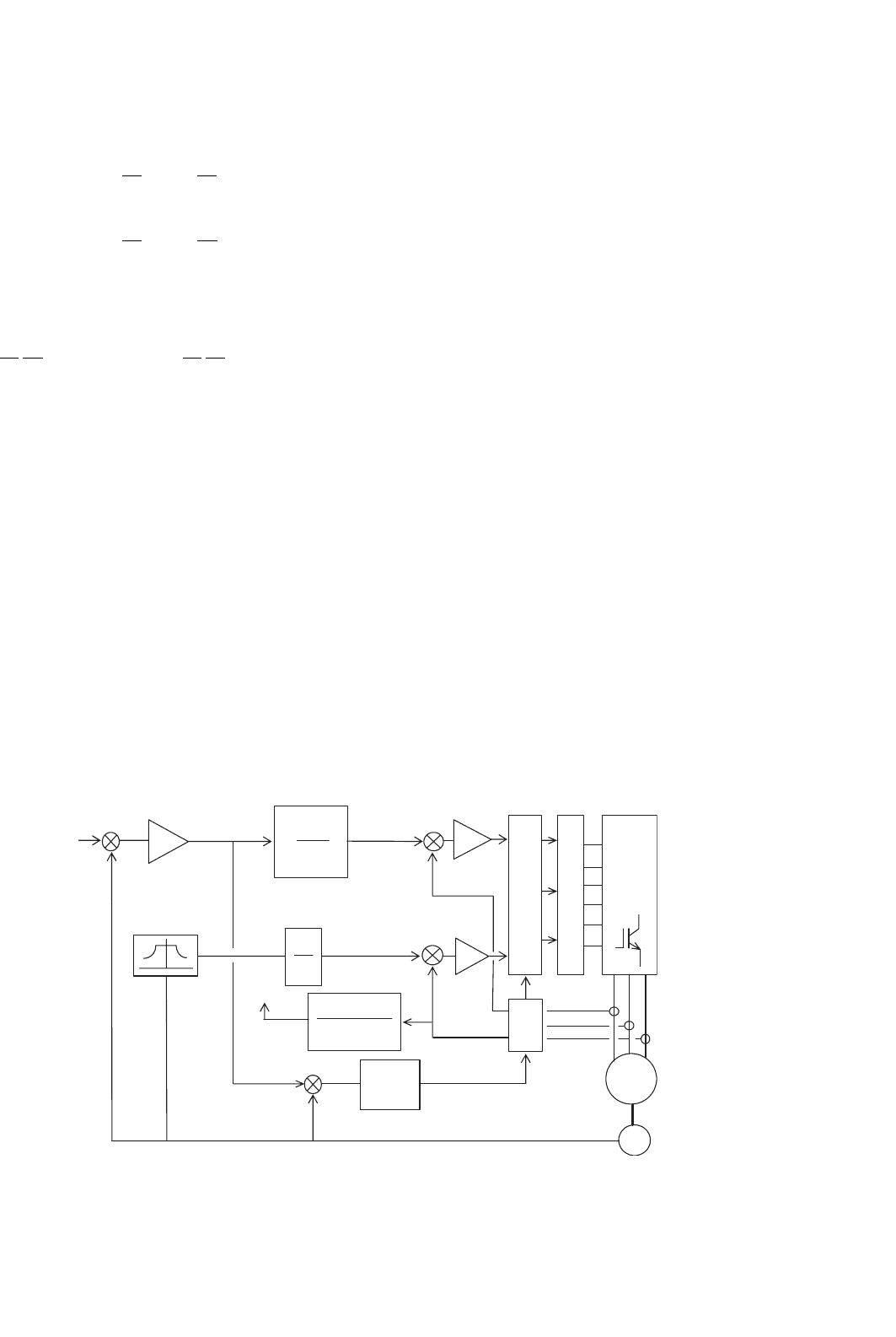
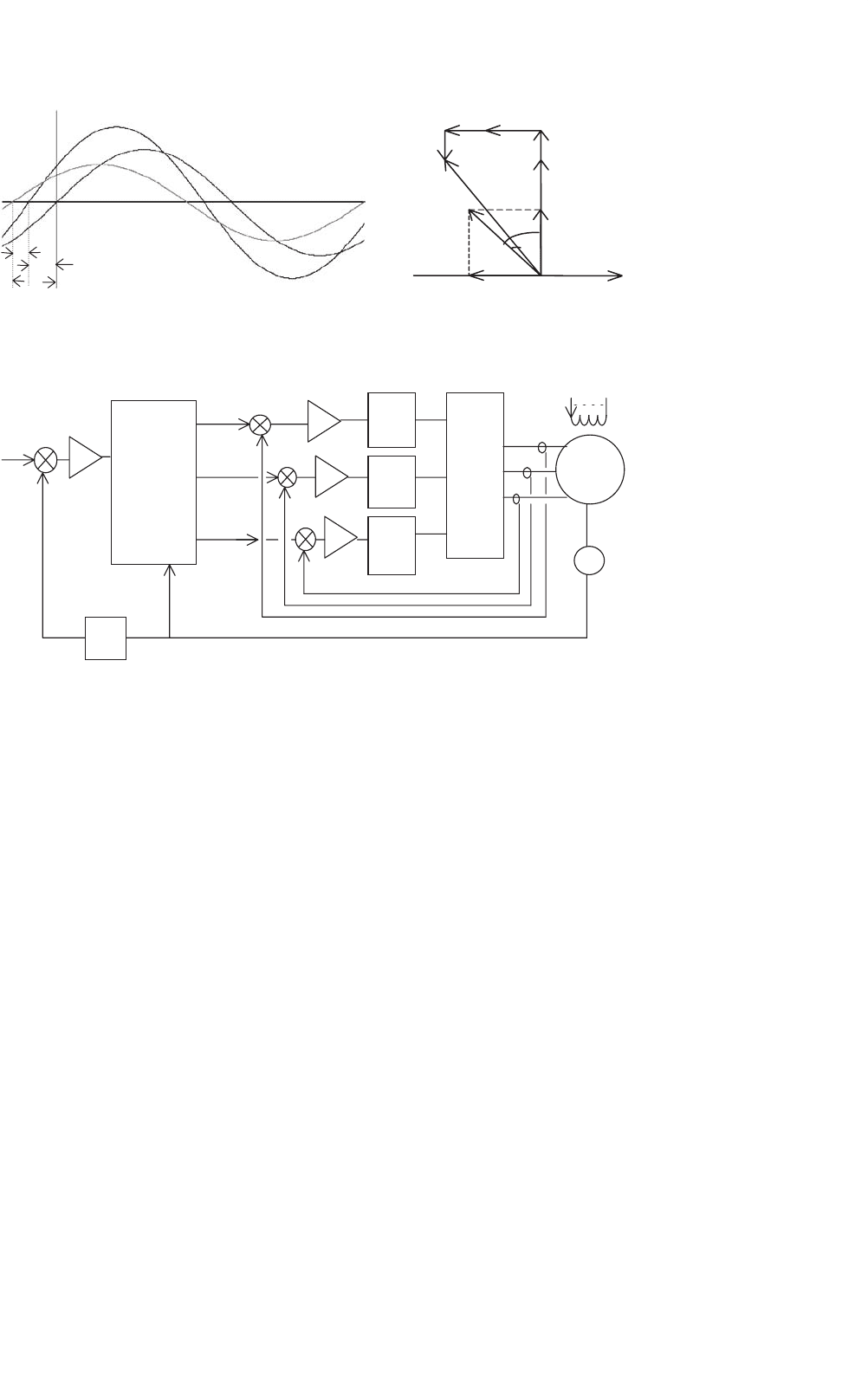
FIGURE 33.28 Indirect rotor flux oriented vector control scheme.
33.3.4.2 Indirect Rotor Flux Oriented (IFOC) Vector
Control
In the indirect scheme, the relationship between the slip fre-
quency and current i
qs
given by Eq. (33.52) is used to relate
the compensated speed error ω
1
−ω
r
to i
qs
. The i
qs
, in turn, is
used to develop to the demanded torque T
∗
according to the
Eq. (33.56). The rotor flux is maintained at the base value for
operation below speed, and it may be reduced to a lower value
for field weakening above base speed. The orthogonal relation-
ship between the torque-producing stator current i
qs
and the
flux-producing stator current i
ds
is maintained at all times by
generating the stator current references in the synchronously
rotating dq reference frame, using sine and cosine functions of
angle θ
1
. This angle is obtained as indicated in Fig. 33.28.
The compensated speed error produces the current refer-
ence i
∗
qs
according to Eq. (33.56). The current reference i
∗
qs
also gives the slip speed ω
sl
, according to Eq. (33.53). The slip
speed ω
sl
is added to the rotor speed ω, to obtain the stator fre-
quency ω
1
. This frequency is integrated with respect to time
to produce the required angle θ
1
of the stator mmf relative
to the rotor flux vector. This angle is used to transform the
stator currents to the dq reference frame. Two independent
current controllers are used to regulate the i
q
and i
d
currents
to their reference values. The compensated i
q
and i
d
errors
are then inverse transformed into the stator a–b–c reference
frame for obtaining switching signals for the inverter via PWM
or hysteresis comparators.
It is clear that this scheme uses a feedforward scheme, or
a machine model, in which the current reference for i
qs
is
also determined by the rotor time constant T
r
. This is also
indicated in Fig. 33.28. The rotor time constant T
r
cannot be
expected to remain constant for all conditions of operation.
33 Motor Drives 877
1500 rev/min
3.
4 Amp
1.8 s
A
B
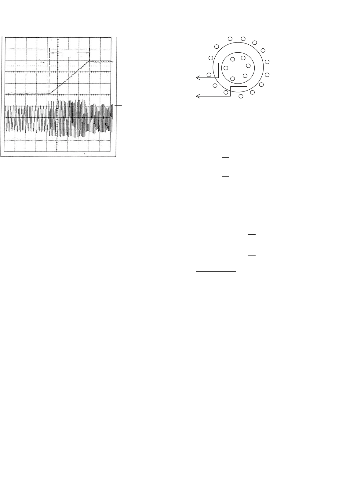
FIGURE 33.29 Speed and current responses of an induction motor
drive under the IFOC scheme of Fig. 33.28.
Its considerable variation with operating conditions means
that the slip speed ω
sl
, which directly affects the developed
torque and the rotor flux vector position, may vary widely.
Many rotor time-constant identification schemes have been
developed in recent years to overcome the problem.
The mandatory requirement for a rotor-speed sensor is
also a significant drawback, because its presence reduces
the reliability of the IFOC drive. Consequently, sensorless
schemes of identifying the rotor flux position have also drawn
considerable interest in recent years.
Figure 33.29 shows the transient response of an induction
motor under the IFOC drive scheme of Fig. 33.28. In this case,
the drive accelerates a large inertia load from standstill to the
base speed of 1500 rev/min. It is clear that the overcurrent
transients of Fig. 33.21 are eliminated, while the motor accel-
erates under a constant torque (implied by the constant rate at
which the speed increases) and settles at the final speed with
little over- or under-shoot in speed. Clearly, rotor and airgap
fluxes remain constant at all times.
33.3.4.3 Direct Vector Control with Airgap Flux
Sensing
In the direct scheme, use is made of the airgap flux linkages
in the stator d- and q-axes, which are then compensated for
the respective leakage fluxes in order to determine the rotor
flux linkages in the stator reference frame. The airgap flux
linkages are measured by installing quadrature flux sensors in
the airgap, as indicated in Fig. 33.30.
l
s
qs
l
s
ds
FIGURE 33.30 Quadrature sensors for airgap flux for direct vector
control.
By returning to Eqs. (33.32)–(33.40) in the stator reference
frame and using some simplifications, it can be shown that
λ
s
qr
=
L
r
L
m
λ
s
qm
−L
lr
i
s
qs
(33.57)
λ
s
dr
=
L
r
L
m
λ
s
dm
−L
lr
i
s
ds
(33.58)
where the superscript s stands for the stator reference frame.
Since the rotor flux rotates at a synchronous speed with respect
to the stator reference frame, the angle θ
1
used for the co-
ordinate transformations in Fig. 33.27 can be obtained from
cos θ
1
=
λ
s
dr
ˆ
λ
r
(33.59)
and sin θ
1
=
λ
s
qr
ˆ
λ
r
(33.60)
where
ˆ
λ
r
=
λ
2
dr
2
+
λ
s
qr
2
The control of torque via i
qs
and the rotor flux via i
ds
, subject
to satisfying conditions (33.50) and (33.51), remain as indi-
cated in Fig. 33.28, according to the basic principle of vector
control.
The requirement of airgap flux sensors is rather restrictive.
Such fittings also reduce reliability. Even though this method
of control offers better low-speed performance than the IFOC,
this restriction has practically precluded the adoption of this
scheme. In an alternative method, the d- and q-axes stator flux
linkages of the motor may be computed from integrating the
stator input voltages.
33.4 Synchronous Motor Drives
33.4.1 Introduction
Variable-speed synchronous motors have been widely used
in very large-capacity (>MW) pumping and centrifuge-
type applications using naturally commutated current-source
878 M. F. Rahman et al.
thyristor converters. At the low-power end, the current-source
SPWM inverter-driven synchronous motors have become very
popular in recent years in the form of permanent-magnet
brushless dc and ac synchronous motor drives in servo-type
applications. There are certain features of three-phase syn-
chronous motors that have allowed them, especially the lower
capacity motors, to be controlled with high dynamic perfor-
mance using cheaper control hardware than is required for
the induction motor of similar capacity. Since the average
speed of the synchronous motor is precisely related to the
supply frequency, which can be precisely controlled, multi-
motor drives with a fixed speed ratio among them are also
good candidates for synchronous motor drives. This section
begins with the performance of the variable-speed nonsalient-
pole and salient-pole synchronous motor drive using the
steady-state equivalent circuit followed by the dynamics of the
vector-controlled synchronous motor drive.
33.4.2 Steady-state Equivalent-circuit
Representation of the Motor
Some of the operating characteristics of variable-frequency
voltage- and current-source driven synchronous motors can
be readily obtained from their steady-state equivalent repre-
sentation, as was the case with the scalar controls of induction
motor drives. Assuming balanced, sinusoidal distribution of
stator and rotor mmfs and an uniform airgap (nonsalient-
pole motor), the per phase equivalent circuit of Fig. 33.31
represents the motor at a constant speed.
The representation in Fig. 33.31 is in terms of the RMS volt-
age V applied to the motor phase winding which consists of
the phase resistance R, synchronous reactance X
s
(in /phase),
and the per phase induced voltage E
f
. The back-emf E
f
devel-
ops in the stator phase winding as a result of rotor excitation
supplied from an external dc source via slip rings or by per-
manent magnets in the rotor. The phasor E
f
has an arbitrary
IR
IR
jIXs jIXs
jIXs
jI
q
Xs
I
q
I
d
jI
d
Xs
V
V
V
q-axis
d-axis
(a) (b) (c)
E
f
E
f
E
f
q
q
q
d
d
d
I
I
I
l
f
g
g
g
l
f
l
f
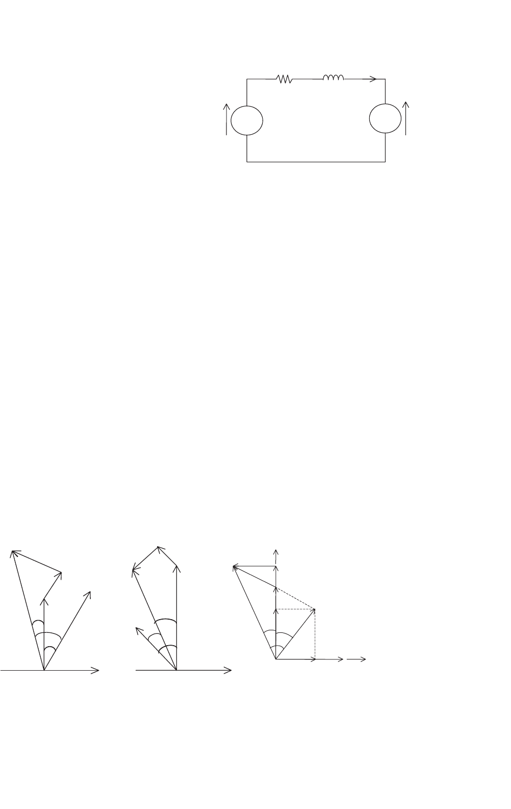
FIGURE 33.32 Phasor diagrams of synchronous motors: (a) under-excited nonsalientpole motor; (b) overexcited nonsalient-pole motor; and
(c) under-excited salient-pole motor.
R
jX
s
= jwL
s
I
V∠0° E
f
∠d°
∼
∼
FIGURE 33.31 Equivalent circuit of a nonsalient pole motor.
phase angle δ with respect to the input voltage V . This is the
load angle of the motor.
Unlike the induction motor, a synchronous motor may
derive part or all of its excitation from the rotor via rotor
excitation. For small synchronous motors that are used in
the brushless dc and ac servo applications, this excitation is
derived from permanent magnets in the rotor. This is read-
ily and economically obtained with the modern permanent
magnets, thus dispensing with the slip-ring-brush assembly.
The i
2
R losses in the rotor windings with the external excita-
tion are also eliminated. These magnets also allow considerable
reduction in space requirement for the rotor excitation. For
large synchronous motors, this excitation is supplied more
economically from an external dc source via slip rings or via
an exciter.
The phasor diagrams of Fig. 33.32 may be used to ana-
lyze characteristics of the nonsalient-pole synchronous motor
drive. Since the rotor magnetic field may be such that the
motor may develop a back-emf that is smaller or larger than
the ac supply voltage to the stator windings, the motor may
accordingly be under- or overexcited, respectively. The overex-
cited motor will normally operate at a leading power factor,
as is the case in Fig. 33.32b. This is desirable in high-power
applications.
33 Motor Drives 879
In the phasor diagrams of Fig. 33.32c, the stator current I
has been resolved into two components I
d
and I
q
, which are
current phasors responsible for developing mmfs in the rotor
d- and q-axes. These representations are in the stator reference
frame, and hence are sinusoidal quantities at the frequency of
the stator supply.
If the voltage drop across the stator resistance is neglected,
which may be acceptable when the stator frequency is near the
base frequency or higher, the developed torque T of the motor
can be found from the phasor relationships of Fig. 33.32. Thus
T =
3
ω
r
EV
X
s
sin δ =
3P
ω
EV
ωL
s
sin δ =
3PK
φ
L
s
V
ω
sin δ Nm
(33.61)
for the nonsalient-pole motor (also for the sine wave PM ac
motor with rotor magnets at the surface of the rotor) and
T =
3P
ω
r
EV
ωL
d
sin δ +
V
2
2
L
d
−L
q
ωL
d
L
q
sin 2δ
= 3P
K
φ
L
d
V
ω
sin δ +
V
2
2ω
2
L
d
−L
q
L
d
L
q
sin 2δ
Nm
(33.62)
for the salient-pole motor (also for the interior-magnet motor
in which the rotor magnets are buried inside the rotor). Here
the flux constant of the motor, K
φ
, is the ratio of the RMS
value of the phase voltage E
f
induced in the stator only due
to the rotor excitation and speed. Note that for a given rotor
excitation, the ratio K
φ
= E
f
/ω remains constant at all speed.
33.4.3 Performance with Voltage-source Drive
Equations (33.61) and (33.62) imply that if the motor is driven
from a voltage-source supply and if the input voltage to fre-
quency ratio, V–f, is kept constant, the motor will develop
the same maximum torque at all speeds. For the nonsalient-
pole motor, this maximum torque will occur for a load angle
δ = 90
◦
. For the salient-pole motor, this will occur for a
load angle which is also influenced by the relative values of
L
d
and L
q
.
At low speed, where the supply voltage V is small, the
voltage drop in the stator resistance may become significant
compared to E
f
. This may lead to a significant drop in the
maximum available torque, as given by the torque Eqs. (33.63)
and (33.64), which are derived from the phasor diagrams of
Fig. 33.32. The stator per phase resistance R is now included
in the analysis. The developed torque is then given by
T =
3PE
fo
V
1
ω
o
λX
so
sin δ +R
cos δ −
λE
fo
V
1
R
2
+
(
λX
so
)
2
Nm (33.63)
for the nonsalient-pole motor and
T =
3P
ω
o
V
2
1
λ
R+VE
fo
λX
qo
sinδ+
V
2
2
X
do
−X
qo
sin2δ−VRE
fo
cosδ
R
2
+λ
2
X
d
X
q
Nm
(33.64)
for the salient-pole motor where the subscript o refers to
the base quantities and λ refers to the per unit input
frequency f
1
/f
0
.
Equations (33.63) and (33.64) indicate that the maximum
torque that the motor can develop diminishes at low speed
because of the voltage drop across the stator resistance R.
This drop in maximum available torque at low speed can be
avoided by boosting the input voltage at low speed, as indi-
cated in Fig. 33.33a. This voltage boosting is similar to the
IR compensation applied to a variable-frequency induction
motor drive.
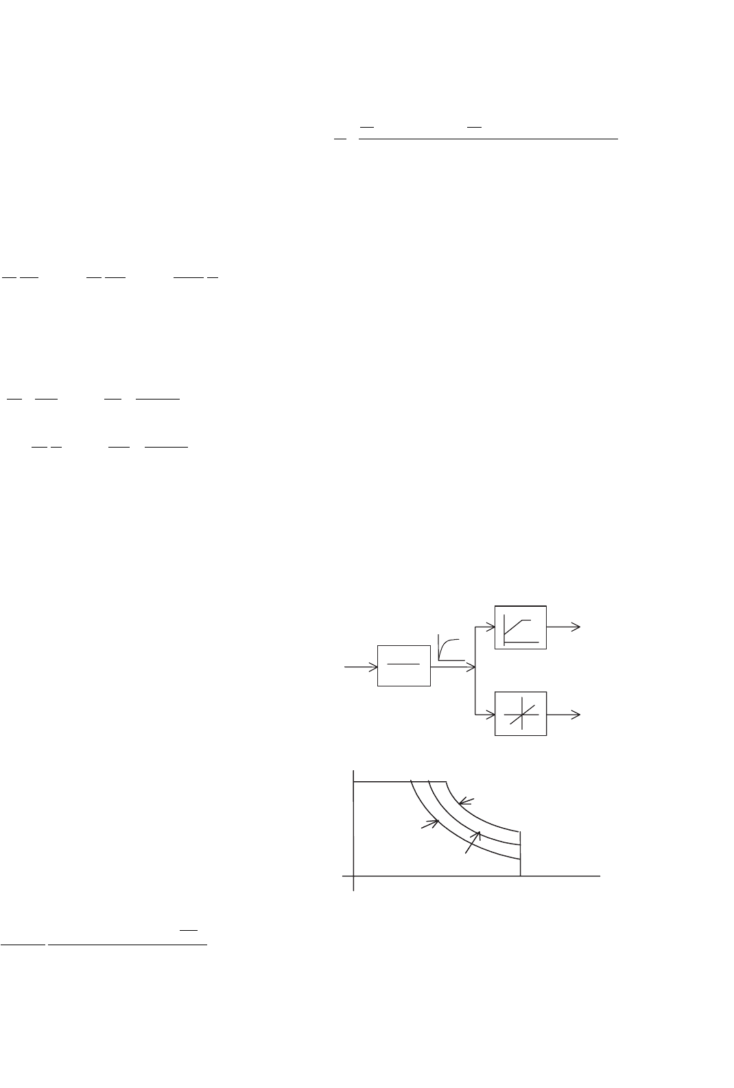
Figure 33.33 indicates an open-loop V–f inverter drive
scheme, similar to the scheme for an induction motor drive
in which the RMS stator input voltage is made proportional
to frequency. The speed reference is passed through a first-
order filter, as shown in Fig. 33.33a, so that a large and abrupt
change in the input frequency command to the inverter is
avoided. The filtered speed reference is translated into a pro-
portional frequency reference f
1
. The voltage reference V
1
is
also proportional to frequency reference, but with a zero fre-
quency bias. The variable RMS input voltage V
1
to the motor
may be obtained from an inverter by SPWM methods or from
a cycloconverter with phase angle control.
1+T
f
s
1
Speed
reference
V
1
reference
f
1
reference
(a)
T
max
(b)
d
max3
w
max
d
max3
>
d
max2
>
d
max1
d
max1
d
max2
FIGURE 33.33 (a) V–f controller for an open-loop inverter drive and
(b) T–ω characteristics with a limited maximum δ for constant-power
operation.
880 M. F. Rahman et al.
The available input voltage V
1
is normally limited by the
available dc-link voltage to the inverter or the ac supply voltage
to a cycloconverter. This limit is normally arranged to occur
at base speed. Above this speed, the stator flux drops leading
to field weakening and constant-power-like operation, as indi-
cated in Fig. 33.33b. In some control scheme, the maximum
load angle δ is not allowed to exceed a certain limiting value
δ
max
. By selecting δ
max
, constant-power operation at various
power levels is possible.
33.4.4 Characteristics under Current-source
Inverter (CSI) Drive
A CSI-driven synchronous motor drive generally gives higher
dynamic response. It also gives better reliability because of the
automatic current-limiting feature. In a variable-speed appli-
cation, the synchronous motor is normally driven from a stiff
current source. A rotor position sensor is used to place the
phase current phasor I of each phase at a suitable angle with
respect to the back-emf phasor (E
f
) of the same phase. The
rotor position sensor is thus mandatory.
Two converter schemes have generally been used. In one
scheme, as indicated in Fig. 33.34, a large dc-link reactor
(inductor) makes the current source to the inverter stiff. The
scheme is suitable for large synchronous motors for which
thyristor switches are used in the inverter. A current loop may
also be established by sensing the dc-link current and by using
a closed-loop current controller that continuously regulates
the firing angle of the controllable rectifier in order to supply
the inverter with the desired dc-link current. It can be shown
that the motor-developed torque is proportional to the level
of the dc-link current.
~
~
~
Current
controller
T
1
T
1
−T
6
T
4
T
3
T
6
T
5
T
2
DC Link
Inductor
I
DCLlink
+
E
q
I
ref
I
DCLink
Converter
Switching
Circuit
a
−
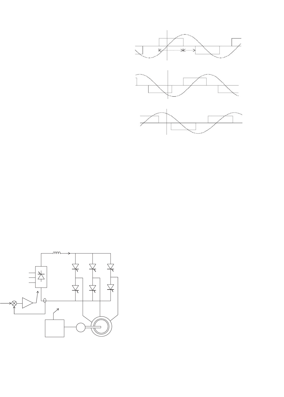
FIGURE 33.34 Schematic of a current-source inverter (CSI) driven
synchronous motor.
i
a
i
b
i
c
e
a
e
b
e
c
60°120°
FIGURE 33.35 Current waveforms in the dc-link current-source-driven
motor.
The inverter drives the motor with quasi-squarewave cur-
rent waveforms as indicated in Fig. 33.35. The current wave-
forms are switched according to the measured rotor position
information, such that the current waveform in each phase has
a fixed angular displacement, γ, with respect to the induced
emf of the corresponding phase. Because of this, the drive
is sometimes referred to as self-controlled. The angular dis-
placement of these current waveforms (or their fundamental
components) with the respective back-emf waveforms is indi-
cated in Fig. 33.35. Because of the large dc-link inductor, the
phase currents may be considered to remain essentially con-
stant between the switching intervals. The quasi-square current
waveforms contain many harmonics, and are responsible for
large torque pulsations that may become troublesome at low
speed.
In the forgoing scheme, the motor can be reversed eas-
ily by reversing the sequence of switching of the inverter.
It can also be braked regeneratively by increasing the firing
angle of the input rectifier beyond 90
◦
while maintaining the
dc-link current at the desired braking level until braking is no
longer required. The rectifier now returns the energy of the
overhauling load to the ac mains regeneratively.
In another scheme, which is preferred for lower capacity
drives for which higher dynamic response is frequently sought,
phase currents are regulated within the inverter. The inverter
typically employs gate turn-off switches, such as the IGBT, and
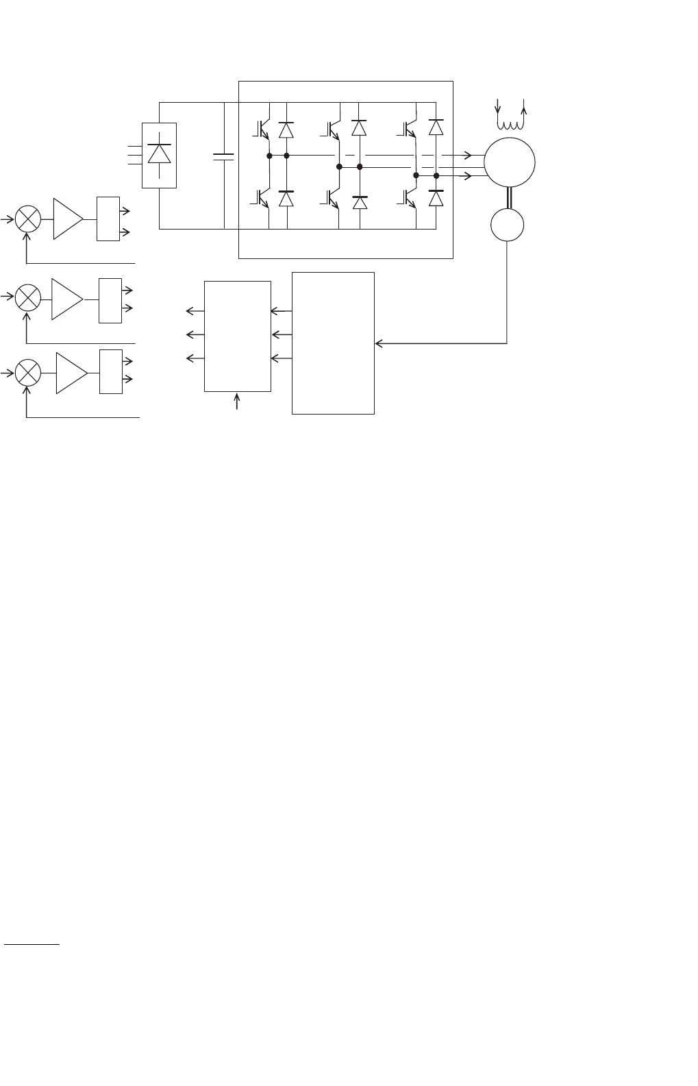
pulse-width modulation techniques, as indicated in Fig. 33.36.
Motor currents are sensed and used to close independent
current controllers for each phase. Normally, two current
controllers suffice for a balanced star-connected motor. Three-
phase sinusoidal ac currents are supplied to the motor, the
33 Motor Drives 881
−DC-Link
+DC-Link
≈
−
E
I
f
−
−
Look
Up
Table
Variable-
Amplitude
Sinusoidal
Current
Reference
Generation
P
W
M
P
W
M
P
W
M
T
1
T
4
T
6
T
3
T
5
T
2
T
4
T
3
T
6
T
5
T
2
T
1
AC supply
i
a
i
c
m
i
aref
i
bref
i
cref
i
a
i
b
i
c
i
aref
i
bref
i
cref
Motor
FIGURE 33.36 Control scheme of the SPWM current-source drive.
amplitude and phase angle of which can be independently con-
trolled as required. The references for the current controllers
are obtained from a three-phase current reference generator
that is addressed by the feedback of the rotor position. The
rotor position is continuously measured by a high-resolution
encoder. In this way, the current references, and hence the
actual stator currents are synchronized to the rotor.
33.4.5 Brushless DC Operation of the CSI-driven
Motor
The torque characteristic of the CSI drive scheme of the fore-
going section can be easily analyzed using the phasor diagrams
shown earlier, if the harmonics in the motor current waveform
are neglected or if the motor current waveforms are indeed
sinusoidal as in the second scheme described earlier. In the
following analysis, it is assumed that the supply current wave-
forms are sinusoidal. It is also assumed that the phase angle
of these current sources with respect to the induced voltage in
each phase can be arbitrarily chosen.
The phase back-emf and the current waveforms and the
phasor diagram of the nonsalient-pole motor are shown in
Fig. 33.37. The phase angle γ between the E
f
and I phasors and
the RMS value (or amplitude) of I are determined according
to the desired torque and power factor considerations. The
developed torque is found from the phasor diagram to be
T =
3E
f
I cos γ
ω
r
= K φI cos γ Nm (33.65)
If the angle γ = 0
◦
is chosen, the familiar dc-motor-like
torque characteristic is obtained. It should be noted from the
forgoing that the developed torque at any speed is independent
of R since a high-gain (stiff) current-source drive is used. Note
also that the ratio E
f
/ω at any operating speed is proportional
to the amplitude of the stator flux linkage, λ
f
, due to rotor
excitation. For fixed rotor excitation this ratio is a constant.
Equation (33.65) indicates that the developed torque of a
nonsalient-pole synchronous motor can be controlled by con-
trolling the amplitude of the rotor field (field control), or
more conveniently, by controlling the amplitude of the stator
phase current. The highest torque per ampere characteristic is
achieved when γ = 0
◦
. Note that the operation with a fixed γ
angle is key to this dc-motor-like torque characteristic.
33.4.5.1 Operation with Field Weakening
If the stator impedance drop is neglected, the maximum E
f
is largely determined by the dc-link voltage and E
f
= Kλ
f
ω
implies that speed ω can be increased by decreasing λ
f
. Conse-
quently, the operation above base speed is normally achieved
with field weakening. In this speed range, because of the
limited dc-link voltage, the rotor field must be weakened; oth-
erwise, the amplitude of the phase-induced emf will exceed the
dc-link voltage and current control will not be effective. Field
weakening is a means of keeping this voltage at the rated level
for speeds higher than the base speed.
The flux linkage due to the rotor excitation, λ
f
, can be
adjusted when a variable rotor supply is available. This may
also be achieved by demagnetizing the rotor mmf by using
882 M. F. Rahman et al.
(a) (b)
V
q-axis
I
I
q
v
a
i
a
γ
θ
δ
e
fa
jI
q
X
s
jI
d
X
s
I
d
R
I
q
R
E
f
d
g
q
I
d
l
f
d-axis
FIGURE 33.37 Phasor relationships of CSI-driven motor: (a) back-emf and current waveforms and (b) the phasor diagram.
q-axis
E
f
I
q
I
d
l
f
d-axis
I
FIGURE 33.38 Field weakening using stator mmf.
the mmf produced by the stator currents. For motors with
permanent-magnet excitation, the latter is the only means
of weakening the λ
f
. Referring to the phasor diagram of
Fig. 33.38, if I is made to lead E
f
, the d-axis component of
I, i.e. I
d
, will lead E
f
by 90
◦
. The mmf due to I
d
then opposes
the rotor d-axis mmf. The net rotor flux linkage along the
q-axis is then given by
λ
f
= λ
f
+L
d
I
d
(33.66)
where I
d
is negative when I leads E
f
. If the airgap is small,
the d-axis component of the armature current may reduce the
rotor flux to the required extent.
33.4.6 Operating Modes
A synchronous motor may be driven with a view to achieving
various operating characteristics, such as power factor com-
pensation, maximum torque per ampere characteristic, and
field weakening. The power factor at which a synchronous
motor operates is an important issue, especially for a large
drive. A large angle θ between the input voltage and current
phasors of the motor results in a poor overall power factor.
Operation of the synchronous motor with a CSI which deliv-
ers the stator current waveforms with phase angle with respect
to the respective phase back-emf waveforms that allows inter-
esting power factor compensation possibilities. Consider the
following three cases.
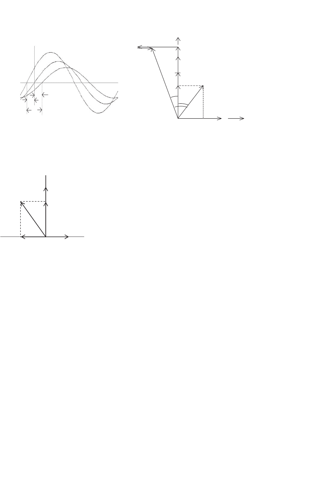
33.4.6.1 Case 1: Operation with I Lagging E
f
In this case, the motor is under-excited and I lags E
f
,byan
angle γ, as indicated in Fig. 33.39. The overall power factor in
this case is lagging, since I lags V by an angle θ. The power-
factor angle θ is larger than γ. Note that I
d
now magnetizes
the rotor field.
33.4.6.2 Case 2: I is in phase with E
f
; Maximum
Torque per Ampere Operation (γ = 0
◦
)
If γ = 0
◦
is used, the motor input current i
a
is in phase with
the back-emf e
a
, as indicated in the waveforms of Fig. 33.40a.
From Eq. (33.65), the developed torque is given by
T = K φI (33.67)
Thus, for a fixed rotor excitation, the developed torque is
the highest that can be achieved per ampere of stator current
I. In other words, if γ = 0
◦
is chosen, the drive operates with
its maximum torque per ampere characteristic. From the pha-
sor diagram of Fig. 33.40b, it is clear that the input current I
phasor now lags the voltage V phasor at the motor terminals.
(see the phasor diagram in the figure). Note that the level of
E
f
,which is determined by the level of excitation, also deter-
mines the angle θ to some extent. Clearly, when maximum
torque per ampere characteristic is required, a power factor
less than unity has to be accepted.
33 Motor Drives 883
(
a
)(
b
)
e
fa
i
a
I
d
I
q
g
I
q
X
s
RI
d
RI
q
V
jI
d
X
s
E
f
I
g
q
l
f
FIGURE 33.39 (a) Phase back-emf and current waveforms and (b) the phasor diagram with I lagging E
f
.
(a) (b)
v
e
fa
i
a
γ = 0
θ
δ
I
q
X
s
V
q
I
q
R
E
f
I = I
q
l
f
d-axis
g = 0°
FIGURE 33.40 (a) Phase back-emf and current waveforms and (b) phasor diagram for I in phase with E
f
.
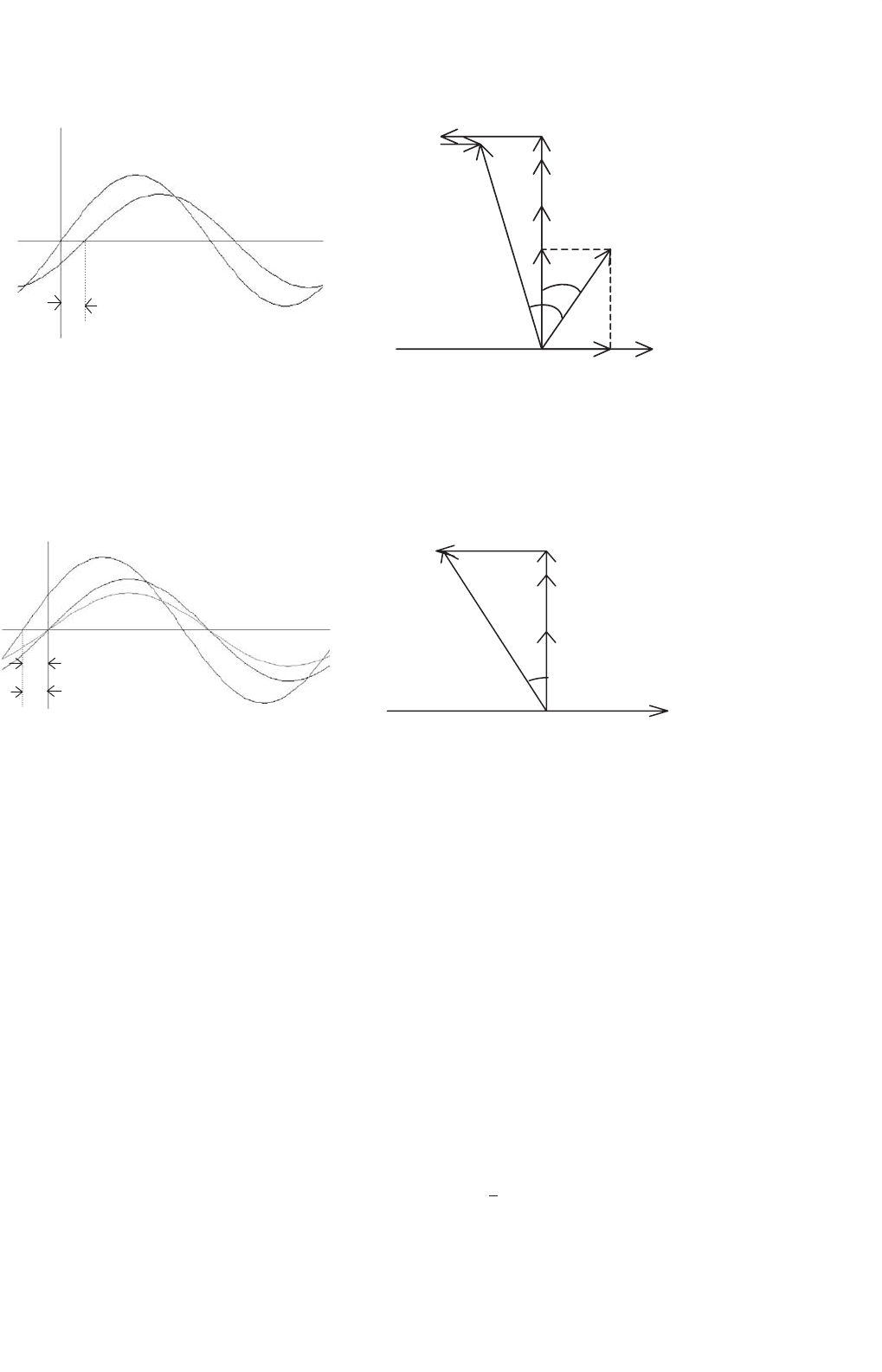
33.4.6.3 Case 3: Operation with I Leading E
f
If I is chosen to lead E
f
, the overall power factor can be
higher, including unity, as is indicated in Fig. 33.41. Note that
the motor now operates with less than maximum torque per
ampere characteristic. Note also that the d-axis component of
I now tends to demagnetize the rotor and that the operation
with field weakening is implied.
With a CSI-driven motor, the amplitude and the angle of
the phase current relative to the back-emf can be selected
according to one of the desirable operating characteristics
mentioned above. Additionally, other operational limits such
as the inverter/motor current limit, the maximum stator volt-
age limit, and the maximum power limit can also be addressed.
The amplitude of the stator current I clearly determines the
developed torque of the motor. Consequently, the error of
the speed controller is used to determine the amplitude of I.
The overall control system with an inner torque loop can be
described by Fig. 33.42.
33.4.7 Vector Controls
The foregoing controls were based on the steady-state equiva-
lent circuit of the motor. Even though the torque Eq. (33.65)
for a current-source drive evokes vector-control-like relation-
ships, they do not address the dynamics of the current controls
as is possible in an orthogonal reference frame. Using an
orthogonal set of reference attached to the rotor, a simple
set of decoupled, dc-motor-like torque control relationships
is readily obtained. Following the transformation technique
used in Section 33.3.4, the stator voltage equations of a
synchronous motor with fixed rotor excitation in the rotor
reference frame are
v
q
v
d
=
R +pL
q
ωL
d
−ωL
q
R +pL
d
i
q
i
d
+
ωλ
f
0
(33.68)
T =
3
2
P
λ
f
i
q
+(L
d
−L
q
)i
d
i
q
(33.69)
884 M. F. Rahman et al.
δ
θ
v
i
a
V
I
γ
e
fa
I
d
R
I
d
jI
d
X
s
jI
q
X
s
I
q
R
E
f
I
q
l
f
I leading
E
f
q
g
FIGURE 33.41 Back-emf and current waveforms and phasor diagram for I leading E
f
.
I
n
v
e
r
t
e
r
P
W
M
P
W
M
P
W
M
i
aref
i
bref
i
cref
E
Motor
Look
Up
Table
&
Current
Profiler
I
f
+
−
−
+
w
ref
w
q
FIGURE 33.42 Structure of a speed-control system with a CSI-driven synchronous motor.
where all the quantities in lower case represent instantaneous
quantities in the rotor dq-frame. The λ
f
is the flux linkage per
phase due to the rotor excitation, ω is the electrical angular
velocity in rad/sec, and P is the number of pole pairs. Here,
p is the time derivative operator d/dt. Assuming the magnetic
linearity, the stator flux linkages are
λ
d
= L
d
i
d
+λ
f
λ
q
= L
q
i
q
(33.70)
Note that the Eq. (33.68) can be written down directly from
Eq. (33.31), taking into account the fixed rotor excitation so
that the third and fourth rows and columns of Eq. (33.31) may
be dropped. Since the reference frame now rotates at the speed
of the rotor, ω
e
= ω. The induced back-emf due to the fixed
rotor excitation occurs in the rotor q-axis and is included in
Eq. (33.68), as a separate term. Similarly, the torque expression
of Eq. (33.69) may also be written down from Eq. (33.41),
using the flux linkages of Eq. (33.70).
Equations (33.67)–(33.69) are for a salient-pole motor for
which L
d
= L
q
. For a nonsalient-pole motor, L
d
is equal to L
q
and the developed torque is proportional to i
q
only. In either
case, the inner torque loop consist of two separate current
loops; one for i
d
and the other for i
q
, as indicated in Fig. 33.43.
The i
q
current loop generally derives its reference signal from
the output of the speed controller and constitutes the inner
torque loop. The reference for the i
d
current loop is normally
specified by the extent of field weakening for which a neg-
ative i
d
reference is used. Otherwise, the d−axis current is
maintained at zero. Note that for large synchronous motors
with variable external excitation, field weakening is normally
applied through adjustment of the rotor excitation, using a
spillover signal from the output of the speed controller.
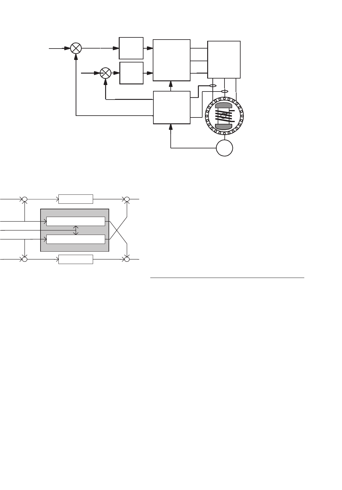
From Eq. (33.68), it is clear that the couplings of q- and
d-axes voltages exist through the d- and q-axes currents,
respectively, and the back-emf. During dynamic operation,
such coupling effects become undesirable. The coupling effects
of d- and q-axes currents and the back-emf into q- and d-axes
voltages, respectively, can be removed by the feedforward
terms shown in the shaded part of the block the diagram of
Fig. 33.44 which also shows the two current-control loops. The
two outputs v
∗
d
and v
∗
q
from the decoupled current controllers
are transformed to the stator reference frame before being sub-
jected to pulse-width modulators or hysteresis comparators.
Note that the current references i
∗
d
and i
∗
q
are obtained with
33 Motor Drives 885
i
q
*
i
d
*
i
q
i
d
d-axis
current
controller
q-axis
current
controller
Inverse
d -q
transformation
d -q
transformation
Inverter
+
+
E
−
−
FIGURE 33.43 Inner torque loop of a vector-controlled synchronous motor drive.
+
+
+
+
+
+
−
−
i
*
d
v
*
d
v
*
q
i
*
q
i
d
i
q
g
q
(t)
g
d
(t)
w
d-axis current controller
wl
f
+ wL
d
i
d
−wL
q
i
q
q-axis current controller
FIGURE 33.44 The d- and q-axis decoupling compensation.
due regard for the desired operating and limiting conditions
as described in Section 33.4.5.
Under this type of control, which is exercised in the rotor
reference frame, the d- and q-axes currents are separately regu-
lated. The purpose of the q-axis current controller is primarily
to control the developed torque, especially for the nonsalient-
pole motor. For this motor, the d-axis current is normally
maintained at zero, when the motor is operated below the
base speed. The d-axis current may be used to weaken the
airgap flux so that the motor operates with a constant power-
like characteristic. It should be noted that the field weakening
may also be carried out more directly by adjusting the rotor
excitation current by using a spillover signal from the speed
controller, when the base speed is exceeded.
The dynamic response of the drive under the vector control
scheme indicated in Fig. 33.44 is the highest possible with a
CSI drive. It should also be noted that the dq currents in the
rotor reference frame vary only the mechanical dynamics of
the rotor. In fact, they are dc quantities when the motor runs
at a constant speed. Consequently, the following error (or lag)
associated with tracking a sinusoidally time varying current
reference, which is the case when current control is exercised
in the stator a–b–c reference frame, can be reduced easily by
using an integral-type current controllers.
33.5 Permanent-magnet AC
Synchronous Motor Drives
33.5.1 Introduction
Since the introduction of samarium cobalt and neodymium–
iron–boron magnetic materials in the 1970s and 1980s, syn-
chronous motors with permanent-magnet excitation in the
rotor have been displacing the dc motor in many high-
performance applications. The trend is more noticeable in
applications requiring high-performance motors of up to a few
kilowatts. In low- to medium-power applications, the superior
dynamics, smaller size, and higher efficiency of motors with
PM excitation in the rotor, compared to all other motors, are
well known. Prior to this development, the ferrite and alnico
magnets were routinely used in small servomotors, with the
magnetic excitation in the outer stator. Such motors need a
brush-commutator assembly to supply power to the armature,
that is a problem. Nevertheless, interesting low-inertia, low-
armature inductance designs are possible that are desirable
for servo applications. One such design is the pancake iron-
less armature with the commutator-brush assembly directly
located on the printed armature. These shortcomings of the
commutator-brush are now avoided by locating the magnets