Pump Handbook by Igor J. Karassik, Joseph P. Messina, Paul Cooper, Charles C. Heald - 3rd edition
Подождите немного. Документ загружается.

6.178 CHAPTER SIX
FIGURE 7 Spacer metal disk coupling (Thomas
Coupling Div./Rexnord)
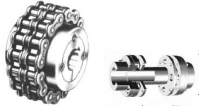
FIGURE 6 Roller-chain mechanically flexible
coupling (Dodge Division, Reliance Electric)
employs two sprocket-like members mounted one on each of the two machine shafts and
connected by an annulus of roller chain. The clearance between sprocket and roller and,
in some cases, the crowning of the rollers provide mechanical flexibility for misalignment.
This type of coupling is generally limited to low-speed machinery.
MATERIAL-FLEXIBLE COUPLINGS These couplings rely on flexing of the coupling element to
compensate for shaft misalignment. The flexing element may be of any suitable material
(metal, elastomer, or plastic) that has sufficient resistance to fatigue failure to provide
acceptable life. Some materials, such as steel, have a finite fatigue limit. A coupling made
of such material must be operated under conditions of load and misalignment that assure
that the stress developed in the coupling element is within that limit. Other materials, such
as elastomers, generally do not have a well-defined fatigue limit. In these cases, however,
heat developed in the material when the coupling flexes can cause failure if excessive.
One type of material-flexible coupling is the metal-disk coupling (Figure 7). This cou-
pling consists of two sets of thin sheet-metal disks bolted to the driving and driven hub
members. Each set of disks is made up of a number of thin laminations that are individu-
ally flexible and compensate for shaft misalignment by means of this flexibility. These disks
may be stacked together as required to obtain the desired torque transmission capability.
This type of coupling requires no lubrication; however, alignment of the equipment must be
maintained within acceptable limits so as not to exceed the fatigue limit of the material.
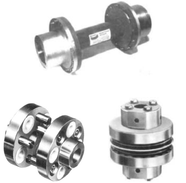
Another example of an all-metal material-flexible coupling is the flexible diaphragm
coupling, shown in Figure 8.This coupling is similar in function to the metal-disk coupling
in that the disk flexes to accommodate misalignment. However, the diaphragm type con-
sists of a single element with a hyperbolic contour that is designed to produce uniform
stress in the member from inner to outer diameter. By more efficiently utilizing the mate-
rial, the weight is reduced correspondingly, thus making this coupling suitable for high-
speed applications.
Material-flexible couplings employing elastomer materials are numerous and their
designs are varied. By definition, an elastomer is a material that has a high degree of elas-
ticity and resiliency and will return to its original shape after undergoing large-amplitude
deformations. One example of an elastomer coupling is the pin-and-bushing coupling (Fig-
ure 9). This design comprises two flanged hub members, one mounted on each machine
shaft. The flange of one hub is fitted with pins that extend axially toward the adjacent
shaft. The other flange is equipped with rubber bushings, which generally have a metal
6.3.1 PUMP COUPLINGS AND INTERMEDIATE SHAFTING 6.179
FIGURE 8 Diaphragm material-flexible coupling (Fluid Power Division, Bendix)
FIGURE 9 Pin-and-bushing elastomer coupling
(Ajax Flexible Coupling)
FIGURE 10 S1eeve-type elastomer coupling (T B.
Woods)
sleeve at the center. The pins fit into these sleeves and provide transmission of torque
through the bushings. Because the bushings are made of flexible material, they can accept
slight angularity or offset conditions between the two flanges.
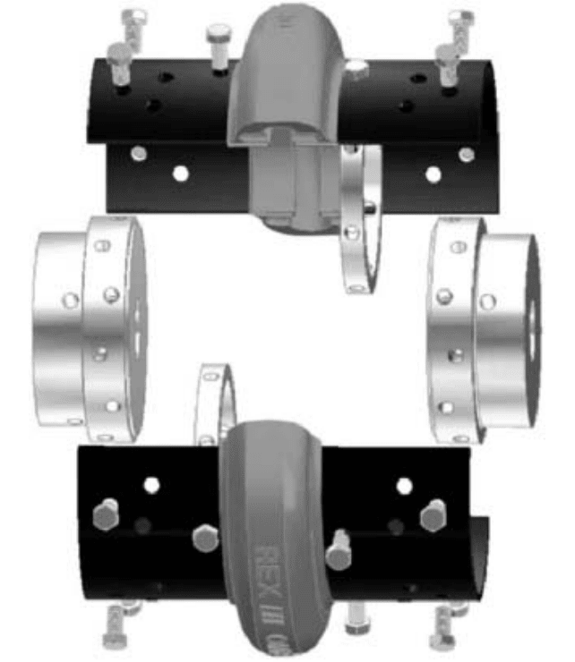
A second group of elastomer couplings employs a sleeve-like element that is connected
to a hub member on each shaft and transmits torque through shearing of the flexible ele-
ment. The flexible element may be attached to the machine hubs by a number of different
means: it may be chemically bonded, it may be mechanically connected by means of loose-
fitting splines (Figure 10), or it may be clamped to the hubs and held in place by friction
(Figure 11). Misalignment between shafts is accommodated through flexing of the elas-
tomer sleeve.
A third group of couplings utilizes an elastomer member that is loaded in compression
to transmit load from one shaft to the other. The elastomer material is placed loosely into
cavities formed by members rigidly mounted onto the two shafts (Figure 12). Again, the
elastomer material deflects to compensate for shaft misalignment, and is usually used
when torsional damping is required.
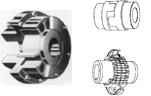
Another type of elastomer coupling that is commonly used on low-power drive systems
is the rubber jaw coupling (Figure 13).The heart of this coupling is a “spider” member, hav-
ing a plurality (usually three) of segments extending radially from a central section. The
6.180 CHAPTER SIX
FIGURE 11 Spacer elastomer coupling (Omega Coupling Div./Rexnord)
hubs, which are mounted on driving and driven shafts, each have a set of jaws corre-
sponding to the number of spiders on the flexible element. The spider fits between the two
sets of jaws and provides a flexible “cushion” between them. This cushion transmits the
torque load as well as compensating for misalignment.
SPRING-GRID COUPLING There is a type of commercially available flexible coupling that
combines the characteristics of mechanically flexible and material-flexible couplings. This
is the spring-grid coupling (Figure 14). This design has two hubs, one mounted on each
machine shaft. Each hub has a raised portion on which toothlike slots are cut. A spring
steel grid member is fitted, or woven, between the slots on the two hubs. The grid element
can slide in the slots to accommodate shaft misalignment and flexes like a leaf spring to
transmit torque from one machine to the other. Unlike most material-flexible couplings,
this design requires periodic lubrication to prevent excessive wear of the grid member.
6.3.1 PUMP COUPLINGS AND INTERMEDIATE SHAFTING 6.181
FIGURE 12 Compression-loaded, loosely fitted
elastomer coupling (Kop-Flex)
FIGURE 14 Spring-grid coupling (Falk Division,
Sundstrand Corp.)
APPLICATIONS
The type of flexible coupling most suitable for a particular application
depends upon a number of factors, including power, speed of rotation, shaft separation,
amount of misalignment, cost, and reliability. In the design of a system, it is the goal of
the designer to use the least expensive coupling that will do the job. In low-cost systems,
cost alone may be the most important criterion, and the least expensive coupling that
transmits the rated power and accepts some small degree of misalignment is generally
the choice, albeit at some sacrifice of reliability and durability. On the other hand, high-
power, high-speed machinery generally represents a critical piece of equipment for a
power station, sewage plant, or other vital process, and in these cases a coupling should
be selected that will not compromise the overall reliability of the system.
Low-power pumps (up to about 200 hp, 150 kW) driven by electric motors can usually
be coupled successfully by any of the couplings described here. Selection procedures vary
from manufacturer to manufacturer, but generally the following data are required: power
rating, speed, anticipated misalignment, and type of pump (reciprocating, vane, centrifu-
gal, and so on).
Pumps of the same power range are very often driven by reciprocating engines (diesel,
gasoline, natural gas). This is quite common in remote areas, such as at pipeline pumping
stations, where a source of electric power is not available. Because this type of prime
mover produces a pulsating type of power, it is often necessary to perform a torsional
vibration analysis of the drive system to ensure that the normal operating speed is well
removed from a speed that may produce a torsional resonant vibration. Such an analysis
requires that the torsional stiffness of the coupling be known. It is quite often possible to
tune the drive system to avoid operating at a resonant condition by selecting the proper
coupling stiffness. The selection data required for a system of this type are the same as
listed above. Most coupling manufacturers will, however, assign a higher service factor to
an application involving a reciprocating prime mover, to compensate for fatigue effects due
to torque fluctuations. In addition, the remote location of many engine-driven pumps indi-
cates a special need to ensure a high degree of reliability of the system.
Another commonly employed prime mover is a steam turbine. These machines,
which range from about 100 hp (75 kW) to well over 50,000 hp (37,000 kW) for pump
drives, operate very efficiently and economically, providing there is a source of steam
FIGURE 13 Rubber jaw coupling (Lovejoy)
available at the installation. Any flexible coupling employed on a machine driven by a
steam turbine must be capable of accepting the thermal gradient at the turbine shaft
and must also accommodate the axial growths of the turbine shaft as it warms up to
operating speed.
Steam turbines are generally high-speed machines (4,000 to as high as 10,000 to
15,000 rpm in some cases) and as such require a relatively high degree of system balance
to avoid critical vibration. Elastomer couplings have occasionally been applied successfully
to steam turbine drives, but because of the high speeds involved, all-metal couplings are
usually employed. The metal coupling most commonly used on this type of drive is the gear
(mechanically flexible) design. High-speed machinery requires that the weight of rotating
components be minimized to decrease shaft deflections and hence increase the lateral crit-
ical speed of the system. The gear coupling is an efficient design for transmitting large
amounts of power at high speeds and with minimum weight. However, disk/diaphragm
coupling designs that are light, flexible, and do not require lubrication are becoming more
popular, especially for higher speed applications.
Where coupling weight and torsional stiffness are critical values to the overall system,
special designs may be created that provide the specific values required for satisfactory
system operation.
BALANCE For higher speed, higher power applications, coupling balance (or residual
unbalance) is an important factor to consider. Elastomeric couplings may have a consid-
erable amount of residual unbalance because of their construction, and they don’t lend
themselves to balancing. The amount of residual unbalance in metal couplings may be
controlled largely by the level of precision to which they are manufactured. When pumps
operate at speeds exceeding four-pole motor speeds and low equipment vibration levels
are critical to service life, elastomeric couplings may not be a good choice. Such require-
ments are important to certain pump types, like those required for API Standard 610:
“Centrifugal Pumps for Refinery, Heavy Duty Chemical, and Gas Industry Services.” For
more information on coupling manufacturing and balance classes and requirements, the
reader is referred to the API and AGMA standards listed at the end of this section.
LIMITED END FLOAT
Many horizontal motor-driven pump systems utilize motors that are
equipped with journal, or sleeve-type, bearings.These bearings are intended only to absorb
the transient thrust created by the motor rotor during acceleration and deceleration. The
coupling for this type of drive should be equipped with suitable provisions for limiting the
axial float of the motor rotor to some fraction of its total float. This may be done by posi-
tioning the motor in the center of its axial travel and then employing a coupling having
a total float that is less than the float of the motor. Any motor thrust is taken by the pump
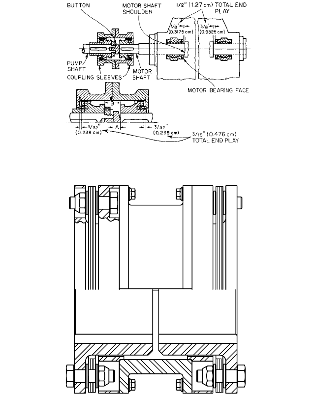
bearing. Gear coupling total float can be limited by inserting a button between shaft ends,
as shown in Figure 15. This type of coupling prevents the motor rotor from ever contact-
ing the thrust shoulders on the shaft bearings. Certain types of elastomer and disk cou-
plings having inherent float-restricting characteristics provide centering without any
additional modifications (Figures 16 and 17).
VERTICAL OPERATIONS As previously noted, rigid couplings are commonly used on vertical-
drive systems where the system characteristics warrant such a coupling. However, many
vertical-drive systems require a flexible coupling to accommodate shaft misalignment. It
is generally possible to use a nonlubricated coupling, such as one of the many elastomer
designs, in a vertical position without modification, provided the shafts are supported in
their own bearings and the coupling does not have to transmit a thrust force. Lubricated
designs, such as the gear and spring-grid types, usually require some modification to make
certain that lubricant is retained in both halves of the coupling.
PUMP DRIVE SHAFT SYSTEMS_________________________________________
Pump drive system arrangements may be classified in one of two categories: those that are
close-coupled, having a shaft separation of a fraction of an inch (not to be confused with
6.182
CHAPTER SIX
6.3.1 PUMP COUPLINGS AND INTERMEDIATE SHAFTING 6.183
FIGURE 15 Motor-driven coupling end float limited by insertion of button between shaft end (Flowserve
Corporation)
FIGURE 16 Metal disk coupling with flanged, tubular spacer (Thomas Coupling Div./Rexnord)
integral motor pumps not having a flexible coupling) and those that, for one or more rea-
sons, have the prime mover located a substantial distance from the pump. These latter
types of systems require a modification to the basic flexible coupling designs previously
described.
Spacers One means of accommodating shaft separation in excess of the normal amount
provided in a standard coupling is to employ a flanged tubular spacer between the two
coupling halves (Figure 18). These components are lightweight and are commonly used
with end-suction pumps, where it is possible to remove the pump impeller while the pump
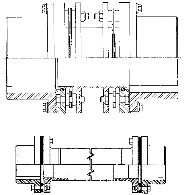
6.184 CHAPTER SIX
FIGURE 18 Tubular spacer coupling (Koppers).
FIGURE 17 Vertical double-engagement gear coupling (Koppers)
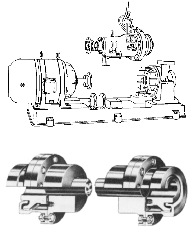
housing and piping, as well as the prime mover, remain in place (Figure 19). For high-
speed drive systems, a lightweight spacer is usually the only practical means of achiev-
ing the goal. This spacer may be used to tune the system torsionally (as previously
discussed) by varying the body diameter and wall thickness. Spacers can be manufactured
in lengths up to several feet, but the cost generally restricts its usage to shorter lengths,
except where no other means is suitable.
Floating Shafts Floating shaft couplings have a purpose similar to that of spacer cou-
plings; namely, to connect two widely separated shafts. The basic difference is in the con-
struction of the component. Whereas spacers are normally made with the body having an
integrally formed flange to connect the two coupling halves, a floating shaft usually is
made by attaching a flange to a piece of solid or tubular shafting by means of mechani-
cal keys or by welding (Figure 20). This type of construction is generally less expensive
than a one-piece spacer, especially when very large shaft separations must be spanned.
Graphite composite center members are also being used. This material has the advantage
of being much lighter and stiffer than standard metal components, allowing longer spans
between bearing supports without adding mass.
6.3.1 PUMP COUPLINGS AND INTERMEDIATE SHAFTING 6.185
FIGURE 19 Spacer coupling enables end-suction pump to be dismantled without moving piping, pump casing, or
driver (Worthington Pump).
FIGURE 20 Section of floating shaft and couplings (Kop-Flex)
Floating shaft arrangements are widely used on horizontal pump applications of all
types and are especially common on vertical pump applications, such as in water pump-
ing and sewage treatment stations. In these latter applications, the pump may be sub-
merged in a pit usually 30 to 50 ft (9 to 15 m) below ground level, whereas the motor (to
prevent damage during flooding) is mounted at ground level. Settings as deep as 100 ft
(30 m) have been constructed. Such systems require long floating shafts, which are gen-
erally made in sections and supported by line bearings at intermediate supports or floors.
Rigid Shafts Vertical centrifugal pumps can be designed to contain their own thrust
and line bearings. These pumps employ a flexible coupling at the pump shaft. When ver-
tical intermediate shafting is used, the shaft need be designed only to transmit torque.
Some pumps are designed to contain only a single line bearing. These pumps require a
rigid coupling at the pump shaft so axial thrust can be carried by the thrust bearing in

6.186 CHAPTER SIX
the driver or gear located above. The constructions of a single oil-lubricated line-bearing
pump is shown in Figure 109 of Subsection 2.2.1. In order to carry thrust, the drive shaft,
if made in sections, must use rigid intermediate couplings and the coupling at the driver
or gear must also be rigid. Intermediate bearings used with rigid shafting must be
designed to provide only lateral support, thereby assuring that all the axial thrust is car-
ried by the driver or gear. An intermediate oil-lubricated sleeve-type guide bearing is
shown in Figure 108 of Subsection 2.2.1. Pump and intermediate shaft sleeve guide bear-
ings can be either grease- or oil-lubricated, and they can also be antifriction if preferred.
A rigid intermediate shaft connected to a pump provided with a rigid coupling must be
designed to carry its own weight, the axial thrust from the pump, and a bending load.
Volute-type centrifugal pumps produce a radial reaction on the pump shaft that in turn is
transmitted to the vertical shafting through the rigid pump coupling. Intermediate bear-
ings then act as line bearings. The bearing supports must also be designed to resist this
bending force.The pump shaft and bearing, intermediate shafts and line bearings, and the
driver or gear shaft and bearings must be treated as a single shaft supported at each bear-
ing when analyzing the critical speed of the entire rotor system. If the intermediate line
bearing supports are assumed to be nodes in the critical speed calculation, these supports
must be absolutely rigid. The supplier of the shafting should, however, confirm what flex-
ibility will be allowed at these supports and give the design forces. The support for the
guide bearings must also be designed not to have a natural frequency of vibration within
the operating speed range of the pump.
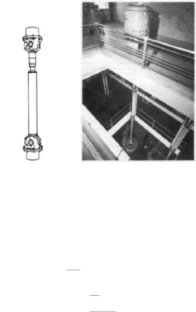
Flexible Drive Shafts Universal joints with tubular shafting (Figure 21) can be sub-
stituted for flexible couplings whenever it is necessary to (a) eliminate the need for crit-
ical alignment, (b) provide wider latitude in placement of pump and driver, and (c) permit
large amounts of relative motion between pump and driver. This type of shafting can be
used horizontally as well as vertically to provide a short spacer arrangement or a large
separation between pump and driver, such as that required for deep settings (Figure 22).
Flanges are furnished to fit pump and driver shafts to the universal joints, which are
splined to allow movement of the shaft. An intermediate steady bearing is required at each
joint, which must also support the weight of a section of shafting (Figure 23). Because of
the spline, pump thrust cannot be taken by the driver, and it is necessary to use a combi-
nation pump thrust and line bearing. Because of the universal joint, the intermediate
bearing or bearings take no radial load from the pumps and therefore act only as a steady
bearing or bearings for the shaft.
The shaft must be selected to transmit the required torque and be of a length and
diameter that will have a critical speed well removed from the operating speed range of
the pump. The support for the guide bearing must not have a natural frequency of vibra-
tion within the speed range. Shafts of this type are often pre-engineered and stocked.
Selection charts are available from the manufacturer to make a proper size and length
selection. Standard tubular, flexible drive shafts have limited torque-carrying capacity.
Design Criteria
TORSIONAL STRESS
The torsional stress in the shafting may be calculated by the following
equations:
for solid shafting
for tubular shafting
where S
S
torsional shear stress, lb/in
2
(N/m
2
)
T transmitted torque, in lb (N m)
S
s
16T
pD
3
o
a1
D
4
D
4
o
b
S
s
16T
pD
3
o
6.3.1 PUMP COUPLINGS AND INTERMEDIATE SHAFTING 6.187
FIGURE 21 Tubular intermediate
shafting and universal units (H. S.
Watson)
FIGURE 22 Sections of flexible shafts and intermediate guide
bearings used to transmit torque from motor located above flood
elevation to pump located below ground (Flowserve Corporation)
D
o
shaft outer diameter, in (m)
D shaft inner diameter (tubular shaft only), in (m)
The allowable shear stress depends upon the material being used and whether it is sub-
jected to other loads, such as bending or compression.The design safety factor on the shaft-
ing should be equal to or greater than those of the other components in the drive train.
CRITICAL SPEED
The critical speed of a drive shaft is determined by the deflection, or “sag,”
of the shaft in a horizontal position under its own weight. The less the sag, the higher the
critical speed. In practical terms, a long, slender shaft will have a low critical speed and
a short, large-diameter shaft will have a very high critical speed. The deflection of a sim-
ply supported shaft is calculated as follows:
noting that
for solid shafting
for tubular shafting I
p1D
4
o
D
4
2
64
I
pD
4
o
64
y
5wL
4
384EI
shaft deflection, in 1m2