Pump Handbook by Igor J. Karassik, Joseph P. Messina, Paul Cooper, Charles C. Heald - 3rd edition
Подождите немного. Документ загружается.

6.168 CHAPTER SIX
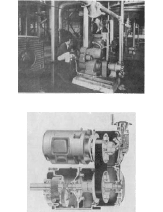
FIGURE 2 Cutaway view of typical mechanical adjustable-speed drive (Reliance Electric)
FIGURE 1 Pump application utilizing typical mechanical adjustable-speed belt drives (Reliance Electric)
be developed at the output shaft of the mechanical adjustable-speed drive. Drive output
power ratings are more fully discussed under “Rating Basis.”
The input speed of the mechanical adjustable-speed drive is typically 1750 or 1160
rpm, as defined by the speed of the drive motor. The output speed of the internal
adjustable-speed belt section goes above and below the drive motor speed. A maximum
speed of 4200 rpm or greater is not uncommon for fractional and small-integral power dri-
ves.The need for stages of output gearing to obtain final output speeds that are usable for
pump or other applications is therefore readily apparent.
6.2.5 ADJUSTABLE-SPEED BELT DRIVES 6.169
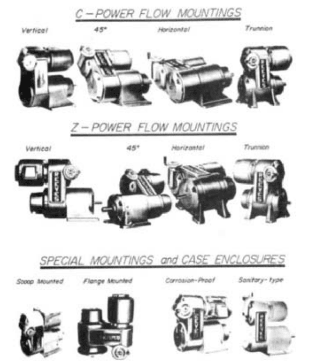
FIGURE 3 Mechanical adjustable-speed drive mounting and special enclosures
Parallel-shaft or right-angle-shaft reducer gearing, at the option of the design engineer
or user, may be incorporated as an integral part of the mechanical adjustable-speed drive
package. Generally speaking, gear reduction is required when drive maximum output
speed must be lower than 1750 rpm or drive minimum output speed lower than 583 rpm.
The American Gear Manufacturers Association (AGMA) does not define standards for
reducers used in adjustable-speed applications. However, most all drive manufacturers
produce reducers for these drives in accordance with accepted AGMA standards for con-
stant-speed reducers.
Where infinite, or stepless, adjustment over a specific finite speed range is necessary,
stepless mechanical adjustable-speed drives are generally most economical for standard
pump application requirements. Initial costs are usually lower than for comparable elec-
tric or hydraulic systems, and the mechanical systems are easier to operate and maintain.
Reliability and accuracy of speed control are advantages of the mechanical adjustable-
speed belt delve package. Construction details, size, and mounting dimensions are not
6.170 CHAPTER SIX
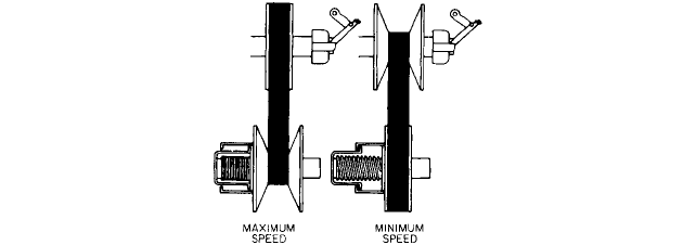
FIGURE 4 Functional diagram for a mechanical adjustable-speed drive belt section (Reliance Electric)
standardized and vary with the manufacturer but all employ dual adjustable-pitch
sheaves mounted on parallel shafts at a fixed center distance and a special wide-section
rubber V belt to provide a compact assembly. Most of the designs utilize spring-loaded
sheaves for control of belt tension.
A high degree of control and flexibility in application is offered by mechanical
adjustable-speed belt drive power packages. Capacities range from fractional to 100 hp (75
kW), with maximum speed ratios of 10:1 in the fractional power sizes, decreasing to 6:1 at
30 hp (22 kW) and 3: 1 in the largest sizes. Multiple-belt drive arrangements are usually
required for capacities over 50 hp (37 kW). Again, depending on capacity, speeds ranging
from a maximum of 16,000 to a minimum of 1.4 rpm are possible, although most of the
standard units are within the 2 to 5000 rpm range.
OPERATING PRINCIPLE _______________________________________________
In Figure 4, the upper disk assembly is the input assembly driven directly by the shaft of
the ac induction motor at a constant speed. This constant-speed disk assembly has one sta-
tionary disk member on the left and one movable, or sliding, disk member on the right. The
sliding member is mechanically attached to a positive shifting linkage arrangement con-
sisting of a thrust hearing, bearing housing, and shifting yoke. This linkage is actuated by
a control hand-wheel or some other speed-changing device.
In the same view, the lower disk assembly is the output assembly, whose speed is
adjustable. In this adjustable-speed disk assembly, the sliding member is next to the
spring cartridge on the left and the stationary member is on the right. Note that this
arrangement is just the opposite of that for the upper, or constant-speed, disk assembly.
This adjustable-speed output shaft of the drive.A flexible, wide-section, rubber V belt con-
nects the two disk assemblies.
Assuming the minimum speed belt position as a starting point, the positive shifting
linkage or the sliding member of the constant-speed disk assembly is moved to the left
toward the fixed member. This positive change forces the wide-section V belt to a larger
diameter in the constant-speed disk assembly. Simultaneously, the belt forces the sliding
member on the adjustable-speed disk assembly against its spring so the belt assumes a
smaller running, or pitch, diameter in this disk assembly. The speed of the output shaft
increases in stepless increments, whereas the drive motor speed remains constant.
Reversing the previous procedures reduces the output shaft speed.
When the V belt is at this maximum diameter in the constant-speed disk assembly, it
is at a minimum diameter in the adjustable-speed disk assembly and the output shaft
speed is at maximum. Conversely, when the V belt is at its minimum diameter in the
constant-speed disk assembly, it is at a maximum diameter in the adjustable speed disk
assembly and the output shaft speed is at minimum.
6.2.5 ADJUSTABLE-SPEED BELT DRIVES 6.171
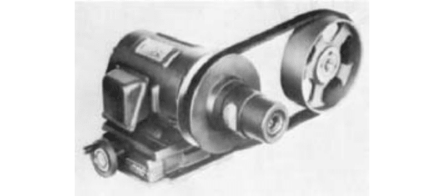
FIGURE 5 Typical motor pulley belt drive with adjustable center distance between driving and driven shafts
(Reliance Electric)
Because one member of each disk assembly is fixed on its shaft, the V belt must move
axially as well as along the inclined surface of the disk to assume different diameters and
cause the speed to change. Centrifugal force makes this composite movement of the belt
effortless when the drive is in operation, but the speed setting of the drive must never be
changed while the drive is not operating and motionless. If speed-setting change is
attempted while the drive is motionless, destructive, crushing forces are imposed on the
belt. These same forces may also damage the positive shifting linkage of the otherwise
rugged mechanical adjustable-speed drive.
OTHER BELT DRIVES _________________________________________________
Other drives of the mechanical adjustable-speed type, such as the single adjustable-motor-
sheave or pulley and the wood block or metal-chain-belt type transmission, are only men-
tioned briefly here because of their rather limited application as pump drives.
The motor sheave, or pulley, illustrated in Figure 5, is a simple, single, adjustable-pitch
device mounted on a motor shaft. It drives by way of a standard or wide-section V belt to
a companion fixed-diameter, flat-face pulley, or V sheave. Driving and driven shafts are
parallel but must be arranged so their center distance is adjustable; this is generally
accomplished by means of a sliding motor base. The entire base assembly is usually oper-
ated as an open belt drive.
The wood-block or metal-chain belt transmission uses the original mechanical
adjustable-speed belt drive operating principle. This drive utilizes a special wide-section
wood-block belt or laminated-metal-chain belt driven by two pairs of positively controlled
variable-pitch sheaves. Movement of the sheave flanges is synchronized by a positive link-
age arrangement.
The transmission-type drive is generally thought of as a low-speed, high-torque device
that can withstand severe overload and abuse for long periods of time.
RATING BASIS_______________________________________________________
The mechanical adjustable-speed drive package is usually rated as a constant-torque,
variable-power device. The power rating is based upon the capacity of the whole unit at
maximum speed setting. When operating at any output speed below this maximum, the
power capacity is reduced in direct proportion.
6.172 CHAPTER SIX
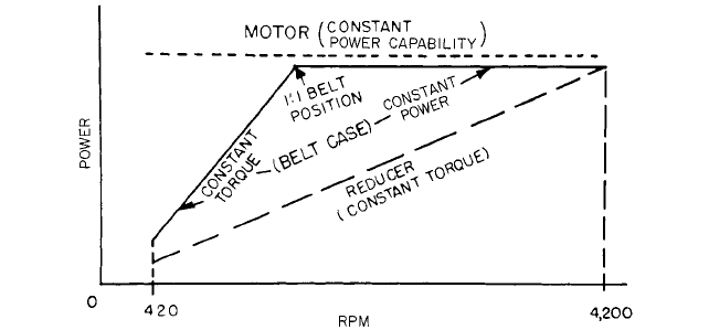
FIGURE 6 Power versus output speed relationship for the motor, belt section, and reducer section of a
mechanical adjustable-speed belt drive
A drive unit is made up of three major components, each of which has its own individ-
ual torque or power output characteristics. For example, the ac induction-drive motor or
prime mover develops constant power at a constant rotational speed.
The adjustable-speed belt section has an output torque characteristic that is a mixture
of both constant torque and variable torque over its speed range. This section has a
constant-power, variable-torque characteristic when operating above a 1:1 belt position
and a constant-torque variable-power characteristic when operating below a 1:1 belt posi-
tion. Finally, a parallel-shaft or right-angle gear reducer section has a constant-torque,
variable-power characteristic. Figure 6 graphically illustrates these relationships.
Because the gear reducer section has a constant-torque characteristic, this section
defines the output characteristic for the entire mechanical adjustable-speed drive.
It should be noted that virtually all manufacturers rate parallel-shaft drives using out-
put shaft power as a base, whereas right-angle output shaft drives are rated on the basis
of input power to the reducer minus reducer efficiency.
Because of the relatively low efficiency of the right-angle worm gear reducers and
right-angle combination worm and helical gear reducers, the power transmission industry
follows the practice of rating these units in terms of power at the input shaft. From the
earlier discussion on operating principle, you will note that the adjustable-speed output
shaft of the belt section of the drive becomes the input shaft of the reducer section of the
same drive.
One or more sections of a drive, usually the belt and reducer sections, may be service-
factored by frame or case oversizing to permit the rating of these sections for constant
power over all or a portion of their speed range. Because the drive motor is a constant-
power device, as already mentioned, oversizing of its frame is unnecessary.
SERVICE FACTORING_________________________________________________
Service factoring of a mechanical adjustable-speed belt drive is common practice when the
normal operating requirements for steady constant-torque loads running 8 hours/day, 5
days/week are to be exceeded.
Drives to be used other-than-normal service as previously described must be selected
by use of modifying factors that will provide correct service capacity. Some unusual service
requirements are moderate to heavy shock loads, 24 hours/day continuous operation, and
constant-power demands over a wide speed range.
6.2.5 ADJUSTABLE-SPEED BELT DRIVES 6.173
Other unusual service conditions may be suggested by the following information check
list. This list itemizes required information data that should be furnished to the variable-
speed drive manufacturer for those applications calling for unusual service.
1. Speed and torque required for the application
2. Value and frequency of peak-load conditions
3. Hours of operation per day or week
4. Frequency of starts and stops
5. Inertia (WK
2
) of the load
6. Frequency of reversals of rotation direction
7. Electric and mechanical overload protection provisions
8. Method used to connect drive output shaft to driven load
9. Any unusual environment or other operating condition
METHODS OF CONTROL ______________________________________________
A variety of control systems have been developed for use with mechanical adjustable-
speed drives. For the majority of pump applications, speed is controlled manually through
a lever, handwheel, or knob attachment. Remote semiautomatic and automatic control
methods in mechanical, pneumatic, or electric forms are also being used.
For manual operation, vernier attachments are often useful to increase the accuracy of
speed adjustment. Cams are occasionally employed, mounted externally or internally, to
assure a prescribed pattern of output characteristics.
Remote control is usually obtained by means of a positioning motor, which is a
fractional-power motor connected to the drive control shifting screw through reduction
gearing.The output speed of the drive is then adjusted from a station at a remote location.
For semiautomatic or automatic operation, control systems usually consist of three ele-
ments: a sensing unit, a receiver, and a positioning actuator. The sensing unit detects
changes in the process being controlled and transmits a signal to the receiver. At the
receiver, the signal is analyzed, amplified, and transmitted to the positioning actuator,
which adjusts the speed of the mechanical adjustable-speed drive accordingly.
If the process or load requirements can be adapted to produce a signal, there should be
a suitable control system that can be used for speed adjustment. The only limitation is
that the load requirements must follow a specific pattern of some type, regardless of
whether the pattern is based on direct, inverse, or proportional relationships.
The pneumatic actuators used for speed adjustment are usually responsive to a 3 to 15-
lb/in
2
(20- to 100-kPa) air signal pressure. These pneumatic positioning devices are actu-
ally analog piloted servovalve positioning devices that can be used in a great variety of
open- and closed-loop process control applications. They can be used to cause a mechani-
cal adjustable-speed drive to either flow or maintain a given process signal from variables
such as liquid level, pressure, flow rate, or any other measurable value. The adjustable-
speed drive thus becomes the final control element in a closed-loop process control system.
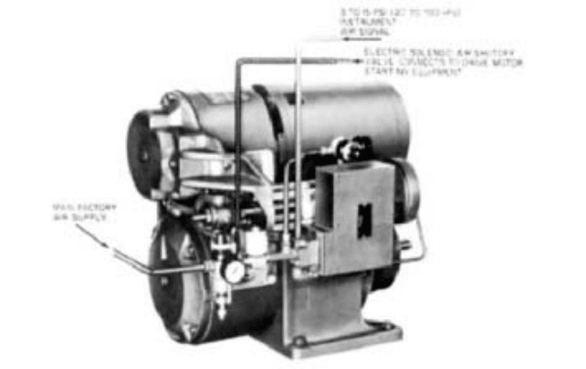
Figure 7 is a typical drive equipped with a pneumatic actuator for speed changing.
APPLICATION GUIDELINES ____________________________________________
The following is a listing of the more common items to consider when specifying a mechan-
ical adjustable-speed belt drive for a specific application:
1. Manufacturer’s size designation of the drive
2. Range of speed variation and actual output speeds
6.174 CHAPTER SIX
FIGURE 7 Mechanical adjustable-speed drive with pneumatic actuator for automatic speed changing (Reliance
Electric)
3. Motor specifications: power rating, electric current (single or polyphase, frequency, and
voltage), type of enclosure, and other special electric or mechanical modifications
4. Special drive output shaft extension
5. Type of control: handwheel, electric remote, mechanical automatic, pneumatic, and so on
6. Manufacturer’s assembly configuration designation and type of mounting, whether
standard floor type, trunnion, ceiling, sidewall, or flange
7. Accessory equipment, such as tachometer, magnetic brake
8. Power rating based on constant torque and maximum output speed
9. Type of case enclosure

6.3.1
PUMP COUPLINGS AND
INTERMEDIATE SHAFTING
FRED K. LANDON
DONALD B. CUTLER
6.175
SECTION 6.3
POWER TRANSMISSION
DEVICES
COUPLING TYPES USED IN PUMP DRIVE SYSTEMS _______________________
A coupling is used wherever there is a need to connect a prime mover to a piece of driven
machinery. The principal purpose of a coupling is to transmit rotary motion and torque from
one piece of equipment to another. Couplings may perform other secondary functions, such
as accommodating misalignment between shafts, compensating for axial shaft movement,
and helping to isolate vibration, heat, and electrical eddy currents from one shaft to
another.
Rigid Couplings Rigid couplings are used to connect machines where it is desired to
maintain shafts in precise alignment. They are also used where the rotor of one machine
is used to support and position the other rotor in a drive train. Because a rigid coupling
cannot accommodate misalignment between shafts, precise alignment of machinery is nec-
essary when one is used.
TYPES There are two commonly used types of rigid couplings. One type consists of two
flanged rigid members, each mounted on one of the connected shafts (Figure 1). The
flanges are provided with a number of bolt holes for the purpose of connecting the two
half-couplings. Through proper design and installation of the coupling, it is possible to
transmit the torque load entirely through friction from one flange to the other, which
assures that the flange bolts do not experience a shearing stress. This type of arrange-
ment is especially desirable for driving systems where torque oscillations occur, as it
avoids subjecting the flange bolts to a shearing stress.
A second type of rigid coupling, known as the split rigid, is split along its horizontal
centerline (Figure 2). The two halves are clamped together by a series of bolts arranged
axially along the coupling. The rigid coupling and machine shafts may be equipped with
conventional keyways, which are in turn fitted with keys to transmit the torque load, or in
6.176 CHAPTER SIX
FIGURE 1 Flanged rigid coupling (Kop-Flex)
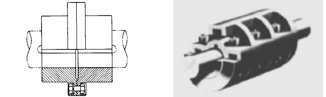
FIGURE 2 Split rigid coupling (Dodge
Manufacturing Division, Reliance Electric)
certain cases the frictional clamping force may be sufficient to permit transmitting the
torque by means of friction between shaft and rigid coupling.This type of coupling is com-
monly used to connect sections of line shafting in a drive train.
A variation to the flanged rigid coupling is known as the adjustable rigid coupling (Fig-
ure 3). This coupling is designed along the lines of conventional rigid couplings, except that
a threaded adjusting ring is placed between the two flanges.This ring engages a threaded
extension on one of the shaft ends. By means of this ring, it is possible to position the pump
shaft axially with respect to the driver.
APPLICATIONS A common application for rigid couplings in the pump industry is in verti-
cal drives, where the prime mover (generally an electric motor) is positioned above the
pump. In such cases, both machines can employ a common thrust bearing, which is gen-
erally located in the motor. The coupling flange bolts must be capable of transmitting any
down thrust from the pump to the motor. In applications where the thrust from the pump
is toward the motor, it is common practice to provide shoulders on the shafts to transmit
the axial force.
Many pump drive systems require a rigid coupling that is capable of providing axial
adjustment to compensate for wear in the pump impeller or impellers.The adjustable rigid
coupling is used for this purpose. The threaded adjusting ring attached to a mating
threaded extension of the pump shaft permits vertical positioning of the impeller or
impellers. The hub, which is mounted on the pump shaft, is equipped with a clearance lit
and feathered key that permit the hub to slide with respect to the shaft. The load capac-
ity of a coupling of this type is generally limited by the pressure on the pump shaft key
because there is no possibility of load being transmitted by interference fit.
A few words of caution should be noted about the use of rigid couplings. First, precise
alignment of machine bearings is absolute necessary because there is no flexibility in the
coupling to accommodate misalignment between shafts. Secondly, accuracy of manufac-
ture is extremely important. The coupling surfaces that interface between driving and dri-
ven shafts must be manufactured with high degrees of concentricity and squareness, to
avoid the transmittal of eccentric motion from one machine to the other.
Flexible Couplings Flexible couplings accomplish the primary purpose of any coupling;
that is, to transmit a driving torque between prime mover and driven machine. In addi-
tion, they perform a second important function: they accommodate unavoidable mis-
alignment between shafts. A proliferation of designs exists for flexible couplings, which
may be classified into two types: mechanically flexible and materially flexible.
MECHANICALLY FLEXIBLE COUPLINGS Mechanically flexible couplings compensate for mis-
alignment between two connected shafts by means of clearances incorporated in the
design of the coupling. The most commonly used type of mechanically flexible coupling is
the gear, or dental, coupling (Figure 4). This coupling essentially consists of two pair of
clearance fit splines. In the most common configuration, the two machine shafts are
6.3.1 PUMP COUPLINGS AND INTERMEDIATE SHAFTING 6.177
FIGURE 3 Adjustable flanged rigid coupling (Kop-
Flex)
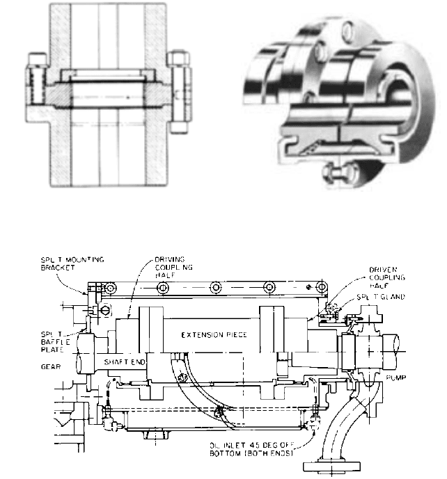
FIGURE 4 Gear-type mechanically flexible coupling
(Kop-Flex)
FIGURE 5 Continuously lubricated coupling (Kop-Flex)
equipped with hub members having external splines cut integrally on the hubs. The two
hubs are connected by a sleeve member having mating internal gear teeth. Backlash is
intentionally built into the spline connection, and it is this backlash that compensates for
shaft misalignment. Sliding motion occurs in a coupling of this type, and so a supply of
clean lubricant (grease or oil, depending on the design) is necessary to prevent wear of
the rubbing surfaces.
If operation cannot be interrupted to lubricate the couplings, constantly lubricated cou-
plings are used, as shown in Figure 5. These consist of an oiltight enclosure bolted at one
end to the stationary portion of either the driving or driven piece of equipment. The other
end of the enclosure has a slip fit inside a cover that is bolted to the other piece of equip-
ment. Some form of packing is used to prevent loss of lubricant at the slip joint. Oil under
pressure is brought through the enclosure and impinges upon the meshing gear teeth of
the coupling, the excess being collected at the bottom of the enclosure and returned to the
oil reservoir.
A second type of mechanically flexible coupling that sees wide usage, especially in low-
cost drive systems, is known as the roller-chain flexible coupling (Figure 6). This coupling