Pumping Station Desing - Second Edition by Robert L. Sanks, George Tchobahoglous, Garr M. Jones
Подождите немного. Документ загружается.

•
Eliminate sharp elbows
in the
piping
system
—
espe-
cially
in the
vicinity
of
pumps
—
since
the fluid
acceleration
due to the
change
in
direction
at
elbows
helps transfer
the
energy
of fluid
pressure pulsations
into bending mode vibrational energy
in the
pipe.
•
Install
flexible
connections
between
the
pump
and
piping
at the
inlet
and
discharge.
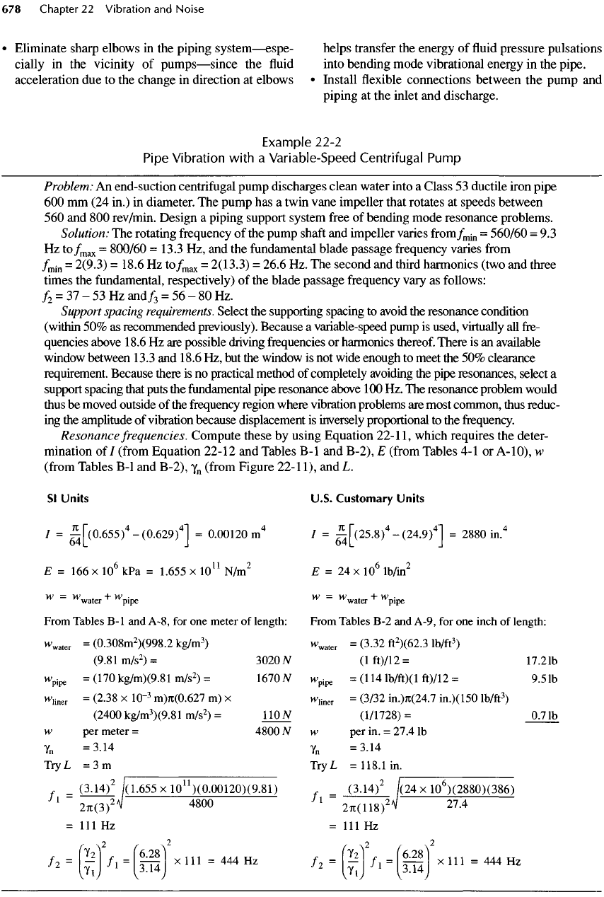
Example
22-2
Pipe
Vibration
with
a
Variable-Speed
Centrifugal Pump
Problem:
An
end-suction centrifugal pump discharges clean water into
a
Class
53
ductile iron pipe
600 mm (24
in.)
in
diameter.
The
pump
has a
twin vane
impeller
that rotates
at
speeds
between
560 and 800
rev/min. Design
a
piping support system
free
of
bending mode resonance problems.
Solution:
The
rotating frequency
of the
pump
shaft
and
impeller
varies
from/
min
=
560/60
= 9.3
Hz
to/
max
=
800/60
=13.3
Hz, and the
fundamental blade passage frequency varies
from
/
min
=
2(9.3)
=
18.6
Hz
to/
max
=
2(13.3)
=
26.6
Hz. The
second
and
third harmonics (two
and
three
times
the
fundamental,
respectively)
of the
blade passage frequency vary
as
follows:
f
2
=
31-
53 Hz
and/
3
=
56-80
Hz.
Support
spacing
requirements.
Select
the
supporting spacing
to
avoid
the
resonance condition
(within
50% as
recommended previously). Because
a
variable-speed pump
is
used, virtually
all
fre-
quencies
above
18.6
Hz are
possible driving frequencies
or
harmonics thereof. There
is an
available
window
between
13.3
and
18.6
Hz, but the
window
is not
wide enough
to
meet
the 50%
clearance
requirement.
Because there
is no
practical method
of
completely avoiding
the
pipe resonances,
select
a
support
spacing that puts
the
fundamental
pipe resonance above
100 Hz. The
resonance problem would
thus
be
moved outside
of the
frequency
region where vibration problems
are
most common, thus reduc-
ing
the
amplitude
of
vibration because displacement
is
inversely proportional
to the
frequency.
Resonance frequencies. Compute these
by
using Equation
22-11,
which requires
the
deter-
mination
of/
(from
Equation 22-12
and
Tables
B-I
and
B-2),
E
(from
Tables
4-1 or
A-IO),
w
(from
Tables
B-I
and
B-2),
y
n
(from
Figure
22-11),
and L.
Sl
Units
U.S.
Customary
Units
/ =
^|~(0.655)
4
-(0.629)
4
1
=
0.00120m
4
/ =
-^|~(25.8)
4
-(24.9)
4
1
=
2880
in.
4
E=
166 x
10
6
kPa =
1.655
x
10
11
N/m
2
E = 24 x
10
6
lb/in
2
w
=
W
water
+
v
Vpe
W
=
W
water
+
^pipe
From
Tables
B-I
and
A-8,
for one
meter
of
length:
From
Tables
B-2 and
A-9,
for one
inch
of
length:
"Wr
=
(0.308m
2
)(998.2
kg/m
3
)
w
water
=
(3.32
ft
2
)(62.3
lb/ft
3
)
(9.81
m/s
2
)=
3020Af
(lft)/12=
17.21b
"We
=
(
17
O
kg/m)(9.81
m/s
2
)
=
1670
W
w
pipe
=(114
lb/ft)(l
ft)/12
=
9.5
Ib
"Wr
=
(
2
-
38
x
10
~
3
m)7i(0.627
m) x
w
liner
=
(3/32
in.)n(24.7
in.)(150
lb/ft
3
)
(2400
kg/m
3
)(9.81
m/s
2
)
=
110
JV
(1/1728)
=
0.7
Ib
w
per
meter
=
4800
N w per in. =
27.4
Ib
Y
n
=3.14
Y
n
=3.14
Try
L
=3m
TryL
=118.1
in.
=
(3.14)
2
/(1.655
x
10
11
)(0.00120)(9^81)
=
(3.14)
2
/(24
x
1Q
6
)(2880)(386)
1
27i(3)
2
^
480
°
l
27t(118)
2
^
27
-
4
=
111 Hz = 111 Hz
'==(;iHii)
2
*'"=—
H^HtS)'*'»=—*
If
these guidelines
are
followed,
the
worst situation
that could result
is a
pipe system resonance excited
by
one of the
higher harmonics
of the
pump.
The
dis-
placement amplification
may
reach
20 or
even
50, but
the
displacement
of the
pipe would also
be
reduced
by
the
increase
in
vibration frequency
and the
decrease
in
energy available
from
the
pump
at
higher harmonics.
By
increasing
the
natural
frequency
of the
piping sys-
tem
from
15
Hz
(the center
of the
available window
between 13.3
and
18.6
Hz) to
112
Hz, the
displace-
ment
amplitude
is
reduced
by a
factor
of
15/112
or
0.134
if
equal energy
in all
harmonics
is
assumed.
If
harmonics
above
/
3
are
assumed
to
have less than 1/10
the
energy
of the
fundamental
(a
safe
assumption
for
centrifugal
pumps), then, even with
a
displacement
amplification
of 50 at
112
Hz
(assuming
the
worst
condition),
the
amplitude
of the
pipe vibration would
be
less than 0.134 times
50
divided
by 10.
This dis-
placement
is
less than
70% of the
value that would
be
expected
at 15 Hz if a
spacing
of 10
m
(30 ft) had
been selected
to fit
into
the
13.3-
to
18.6-Hz
window.
Another solution
to
Example 22-2 would
be to
switch
to a
constant-speed pump.
If the
specified pump
were
changed
to a
triple vane impeller centrifugal
pump
driven
at a
constant speed
of
1200
rev/min,
the
driving frequencies would
be 20 Hz
(the
shaft
speed),
40 Hz (2
times
the
shaft
speed),
60 Hz
(the pump fre-
quency),
120 Hz,
180
Hz, and so on. A
pipe spacing
of
3 m
(1
18
in.) would
not be
satisfactory because
its
res-
onance frequency
(112
Hz) is
close
to the
second har-
monic
of the
blade passage frequency
(120
Hz). With
this pump, pipe resonance should ideally
be
about
90
Hz.
Although
the
90-Hz
pipe resonance would provide
only
30%
clearance
to the
nearest driving frequencies,
it
would
be
preferred because
the
nearest driving fre-
quencies
are
higher harmonics (which typically have
less energy than
the
fundamental)
and
because
the
higher frequency would produce lower displacement
amplitudes. Equation
22-1
1
can be
rearranged
to
solve
for
L,
which yields 3.33
m
(10.9
ft) for 90 Hz.
The
problems introduced
by
variable-speed pumps
are
demonstrated
in
Example 22-2.
The
variable-speed
pump
can
also excite structural resonances
of the
build-
ing,
a
problem discussed
in
detail
in
Section
22-12.
Acoustic Resonances
Periodic pressure
fluctuations
caused
by the
pump
can
also excite acoustic resonances within
the
piping sys-
tem. Just
as
there
are an
infinite
number
of
bending
mode resonances
in a
piping system, there
are
also
an
infinite
number
of
acoustic
resonances.
An
acoustic
resonance
is
created when
a
discontinuity
in the
pip-
ing
system (e.g.,
a
termination, elbow,
or
branch)
reflects
a
pressure wave. When
a
pressure wave propa-
gating down
the
pipe reaches
a
discontinuity,
a
portion
of
the
energy
in the
wave
is
reflected back toward
the
source while
the
rest
of the
energy
in the
wave contin-
ues
down
the
pipe.
If the
length
of the
pipe
and the
speed
of
wave propagation
in the fluid are
such that
the
initial
and
reflected waves
are in
phase,
the
system
operates
at an
acoustic resonance.
In
actuality,
the
pressure wave reflects back
and
forth
at
each
disconti-
nuity
several times, creating what
is
called
a
"standing
wave"
in the
pipe.
The
number
of
times
a
wave
is
reflected
before
it
dissipates depends
on the
type
of
discontinuity (i.e.,
the
strength
of the
reflection
at
each end)
and the
viscous losses
in the
system. Termi-
nations
or
abrupt changes
in
area provide
the
strongest
reflections.
Reflections
from
small branches
and 45°
elbows
are
generally weak enough
to be
disregarded.
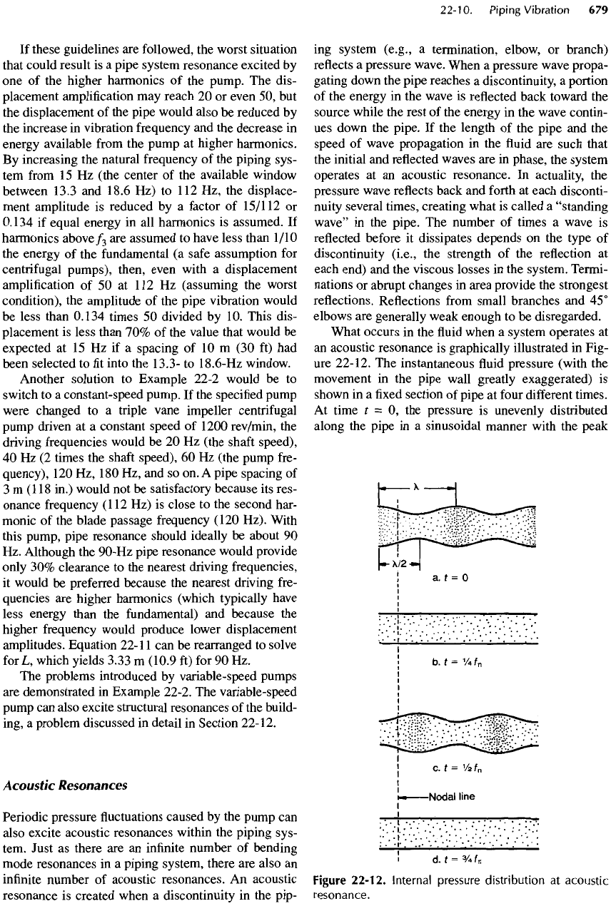
What occurs
in the fluid
when
a
system operates
at
an
acoustic resonance
is
graphically illustrated
in
Fig-
ure
22-12.
The
instantaneous
fluid
pressure (with
the
movement
in the
pipe wall greatly exaggerated)
is
shown
in a fixed
section
of
pipe
at
four
different
times.
At
time
£
= O, the
pressure
is
unevenly distributed
along
the
pipe
in a
sinusoidal manner with
the
peak
Figure
22-12.
Internal
pressure
distribution
at
acoustic
resonance.
pressure locations separated spatially
by a
distance,
y,
the
wavelength
of the
acoustic resonance
in the fluid.
At
t
=/
n
/4,
the
pressure distribution
and
pipe shape
are
uniform.
At t
=/
n
/2,
the
uneven distribution returns,
except that
the
location that
was at
high pressure
(at
t = O) is now a
low-pressure zone,
and
vice versa.
It is
important
to
note that
the
average pressure
in the
pipe
(averaged
over
a
time interval
of
l/f
n
or its
multiple)
is
the
same
at all
points.
There
are fixed
locations along
the
pipe where
the
internal pressure does
not
oscillate about
the
average
pressure. These points
are
called
"nodes,"
and
they also
are
separated
by a
distance, A/2, along
the
pipe. Note
that
the
nodes
and
antinodes
(which
are
regions
of
high-
pressure
fluctuations) of
acoustic resonances
are at fixed
locations that
are
determined
by the
pipe system geom-
etry.
They
do not
move with
the fluid in the
pipe.
The
natural acoustic frequencies
of a
straight, uni-
form
length
of
pipe
are
determined
by the
pipe length,
the
boundary conditions
at
each end,
and the
compres-
sional wave propagation speed
in the fluid
(speed
of
sound).
Depending
on the
impedance presented
by the
discontinuity,
the
acoustic wave reflected
by a
discon-
tinuity
may be
reflected with
or
without
a
180°
phase
reversal.
In
general,
a
pipe opening into
a
large vol-
ume
with
an
abrupt termination creates
a
large
reflec-
tion with
a
180° phase
shift.
This termination
is
called
an
"open-end"
condition.
At the
resonance frequency
of
the
open-end condition,
the
system node
is
located
at
the
termination.
On the
other hand,
a
pipe section
that
terminates with
a
blocked
end
cap,
a tee
connec-
tion,
or a 90°
elbow
is
said
to
have
a
"closed-end"
condition,
which provides
no
phase reversal
for the
reflected
wave. Consequently,
the
dynamic pressure
is
greatest
at the
termination
and the
nodes occur
at
other positions along
the
pipe.
For
straight runs
of
uniform
pipe,
the
acoustic nat-
ural
frequencies
for
pipes open
at
both ends
or
closed
at
both ends
can be
computed
as
follows:
/„ =
ff
(22-14)
where
n
is the
resonance order
(n = 1, 2, 3, . . . ), c is
the
wave propagation speed
of fluid, and L is the
length
of the
column
of fluid
between discontinuities
where
a
reflection
is
anticipated.
For
pipes open
at one end and
closed
at the
other
end,
/
n
=
(2«-D^
(22-15)
Note that
L has
nothing
to do
with
the
spacing
of
pipe supports
or the
spacing
of
couplings.
In
addition
to
individual sections
of
water col-
umns,
it is
also
possible
to
encounter acoustic reso-
nances that incorporate
one or
more individual water
columns,
nonuniform
sections
of
pipe,
and
other com-
plexities.
The
equations
for
computing these frequen-
cies
are
very
complex
—
well
beyond
the
scope
of
this
text
(see Design
of
Piping
Systems
[26]).
Speed
of
Sound
The
speed
of
sound
in
liquids
is
C
0
=
fj-
(22-16)
where
C
0
is
speed
of
sound
in a
free
liquid
in
meters
per
second
(feet
per
second),
y is the
ratio
of
specific
heats (1.0
for
fresh
water
and
1.01
for sea
water),
B is
the
isothermal bulk modulus
of the fluid in
pascals
(pounds force
per
square foot),
and p is the
density
of
the
fluid in
kilograms
per
cubic meter (slugs
per
cubic
foot).
In
general, these quantities vary somewhat
with
temperature
and
pressure
in a
complex manner
as
shown
in
Tables
A-8 and
A-9.
y is
further
defined
as
Cp/c
v
,
where
c
p
is
specific heat capacity
of the fluid at
constant pressure
and
c
v
is the
specific
heat capacity
at
constant volume.
In SI
units,
an
empirical expression
for
the
speed
of
sound
in
fresh
water
is
C
0
=
1403
+
5.02T-0.055T
2
(22-17a)
+
0.0003I
3
+
0.00173P
where
C
0
is the
speed
of
sound
in
meters
per
second,
T
is the
temperature
in
degrees Celsius,
and P is the
gauge
pressure
in
kilopascals.
In
U.S.
customary units,
C
0
=
4248
+
13.237
-0.0727
2
(22-17b)
+
0.000167
3
+
0.0392P
where
C
0
is
speed
of
sound
in
feet
per
second,
T is the
temperature
in
degrees Fahrenheit,
and P is the
gauge
pressure
in
pounds force
per
square inch.
The
speed
of
sound
in
salt water
is
slightly higher
(by
approximately
3%)
than
it is in
fresh
water
due to
the
effects
of
salinity.
The
speed
of
sound
can be
low-
ered dramatically
by air
bubbles
in the fluid. As
long
as
the
concentration
of air is
less than
0.01%
by
vol-
ume,
the
effect
is
insignificant. However, when
the air
concentration reaches
0.1%,
the
speed
of
sound
is
reduced
by
nearly
50%
(see Streeter
and
Wylie
[27]
for
more information
on the
effects
of air
bubbles).
In
addition
to its
dependence
on
temperature
and
pressure,
the
speed
of
sound
is
also influenced
by the
pipe.
The finite
mass
and
compliance
of the
pipe wall
decreases
the
speed
of
sound
as the
pipe wall thick-
ness decreases
and the
pipe diameter increases.
The
expression
for the
speed
of
sound within
a
pipe
is
C=
I
+
B(IDlEe)
(22
'
18)
where
C
0
is
given
by
Equation
22-17,
B is the
bulk
modulus
of the fluid, ID is
internal pipe diameter,
E is
the
modulus
of
elasticity
of the
pipe,
and e is the
thick-
ness
of the
pipe wall.
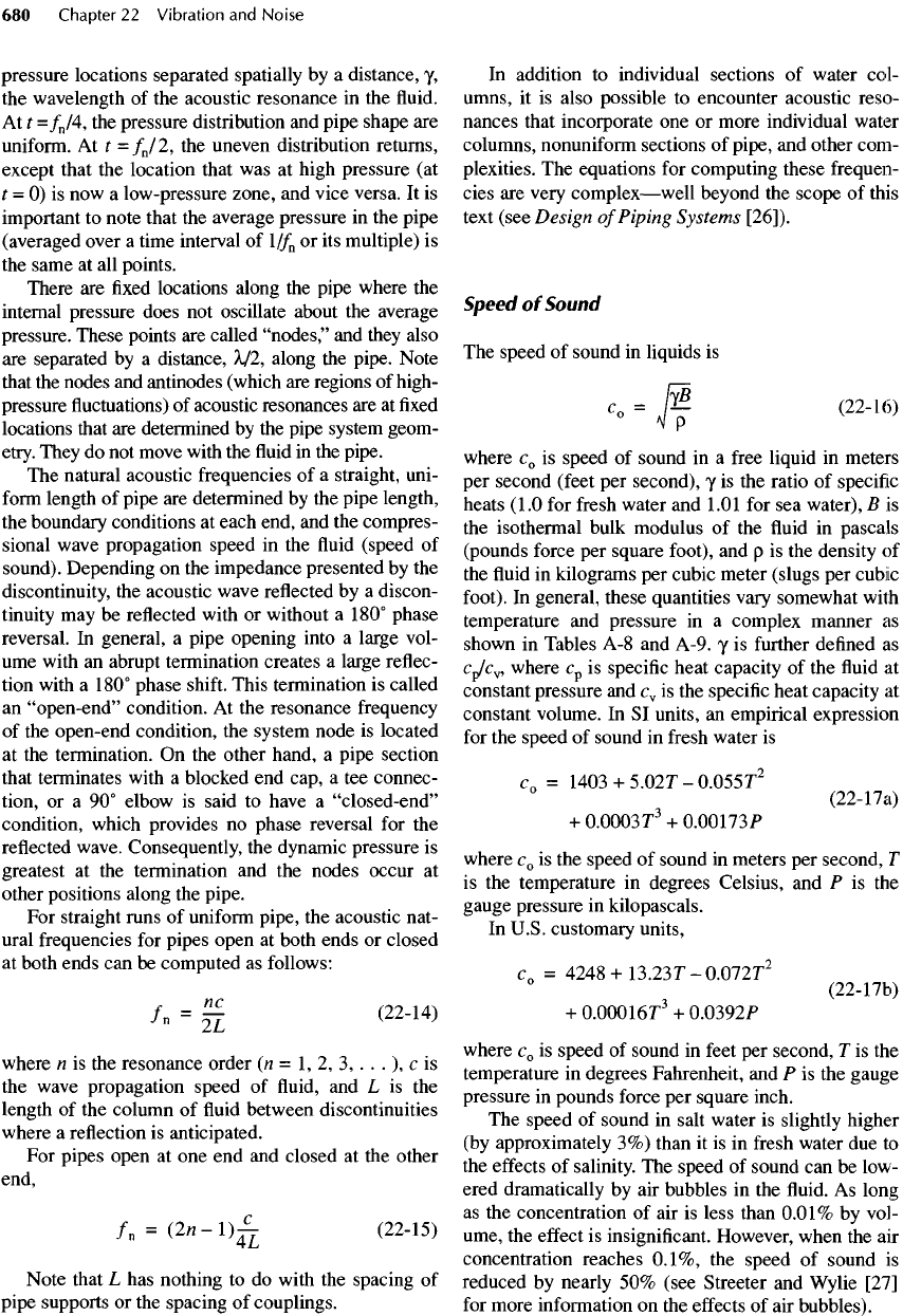
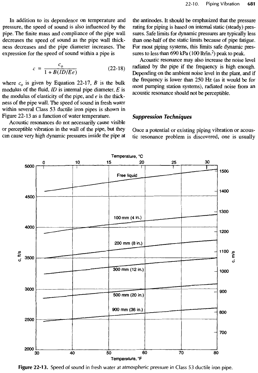
The
speed
of
sound
in
fresh
water
within
several Class
53
ductile iron pipes
is
shown
in
Figure
22-13
as a
function
of
water temperature.
Acoustic resonances
do not
necessarily cause visible
or
perceptible vibration
in the
wall
of the
pipe,
but
they
can
cause very high dynamic pressures inside
the
pipe
at
the
antinodes.
It
should
be
emphasized that
the
pressure
rating
for
piping
is
based
on
internal static (steady) pres-
sures.
Safe
limits
for
dynamic pressures
are
typically less
than
one-half
of the
static limits because
of
pipe
fatigue.
For
most piping systems, this limits
safe
dynamic pres-
sures
to
less than
690
kPa
(100
lb/in.
2
)
peak
to
peak.
Acoustic resonance
may
also increase
the
noise level
radiated
by the
pipe
if the
frequency
is
high enough.
Depending
on the
ambient noise level
in the
plant,
and if
the
frequency
is
lower than
250 Hz (as it
would
be for
most
pumping station systems), radiated noise
from an
acoustic resonance should
not be
perceptible.
Suppression
Techniques
Once
a
potential
or
existing piping vibration
or
acous-
tic
resonance problem
is
discovered,
one is
usually
Figure
22-13.
Speed
of
sound
in
fresh
water
at
atmospheric pressure
in
Class
53
ductile
iron
pipe.
interested
in finding a
remedy
—
or
at
least
a
method
of
improving
the
situation with
as
little
effort
and
expense
as
possible.
The
solution,
of
course, requires
knowledge
of the
nature
of the
problem
as
well
as
some
specifics
concerning
the
frequencies
and
levels
of
vibration.
For
existing
problems,
this information
is
best obtained
by
direct measurement with
an
acceler-
ometer
and a
spectrum analyzer.
These
measurements
usually
require
the
expertise
of a
qualified
vibration
consultant.
Once
the
specifics
of the
problem
are
iden-
tified,
a
proper suppression technique
can
usually
be
applied.
Detuning
Because most vibration problems
are
associated with
the
mechanical resonance
of one or
more elements
in
the
system, detuning
is the
simplest
and
most
effective
method
of
solving
a
piping vibration problem. Detun-
ing
merely implies changing either
the
driving fre-
quency
of the
pump
or the
natural
frequency
of the
piping system. Prior
to
detuning
any
problem system,
it
is
important
to
determine
the
exact driving fre-
quency
and
natural
frequency
of the
installed piping
system, particularly
if the
anticipated solution
is to
make
a
modest change
in
pump
speed.
Without this
information,
it is
possible
to
make
the
situation even
worse
if the new
pump speed turns
out to be
closer
to
the
piping's natural
frequency
than
the
original pump
speed.
Flexible
Connections
A flexible
connection between
the
pump
and the
pip-
ing
can be an
effective
means
of
reducing pipe vibra-
tion
if the
pump
is
vibration-isolated
from
the
structure
and
if the flexible
connection
is
truly
flexible.
When
the
pump
and
piping
are not
isolated
from
the
struc-
ture,
it is
possible
for
this energy
to get
back into
the
piping
via the
common structure.
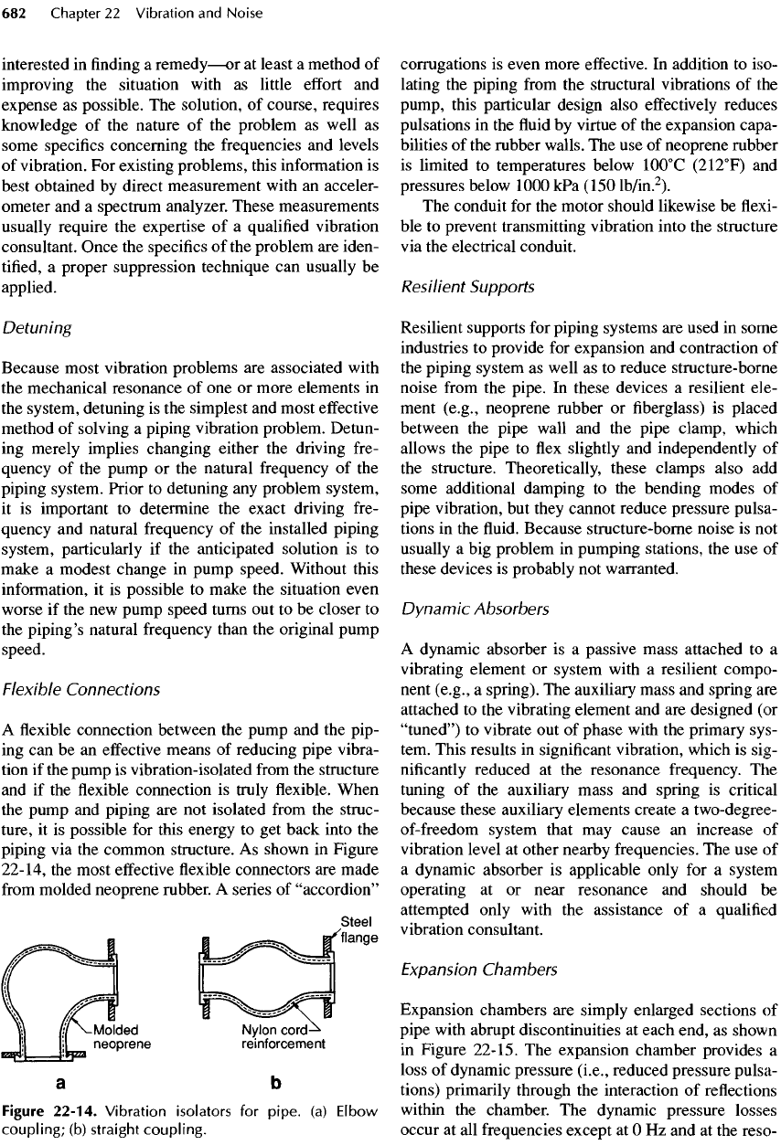
As
shown
in
Figure
22-14,
the
most
effective
flexible
connectors
are
made
from
molded neoprene rubber.
A
series
of
"accordion"
Figure
22-14.
Vibration isolators
for
pipe,
(a)
Elbow
coupling;
(b)
straight coupling.
corrugations
is
even more
effective.
In
addition
to
iso-
lating
the
piping
from
the
structural vibrations
of the
pump,
this particular design also
effectively
reduces
pulsations
in the fluid by
virtue
of the
expansion capa-
bilities
of the
rubber walls.
The use of
neoprene rubber
is
limited
to
temperatures below
10O
0
C
(212
0
F)
and
pressures below 1000
kPa
(150
lb/in.
2
).
The
conduit
for the
motor should likewise
be flexi-
ble to
prevent transmitting vibration into
the
structure
via
the
electrical
conduit.
Resilient
Supports
Resilient
supports
for
piping systems
are
used
in
some
industries
to
provide
for
expansion
and
contraction
of
the
piping system
as
well
as to
reduce structure-borne
noise
from
the
pipe.
In
these devices
a
resilient
ele-
ment (e.g., neoprene rubber
or fiberglass) is
placed
between
the
pipe wall
and the
pipe clamp, which
allows
the
pipe
to flex
slightly
and
independently
of
the
structure. Theoretically, these clamps also
add
some additional damping
to the
bending modes
of
pipe vibration,
but
they cannot reduce pressure pulsa-
tions
in the fluid.
Because structure-borne noise
is not
usually
a big
problem
in
pumping stations,
the use of
these devices
is
probably
not
warranted.
Dynamic
Absorbers
A
dynamic absorber
is a
passive mass attached
to a
vibrating element
or
system with
a
resilient compo-
nent
(e.g.,
a
spring).
The
auxiliary mass
and
spring
are
attached
to the
vibrating element
and are
designed
(or
"tuned")
to
vibrate
out of
phase with
the
primary sys-
tem. This results
in
significant
vibration, which
is
sig-
nificantly
reduced
at the
resonance
frequency.
The
tuning
of the
auxiliary mass
and
spring
is
critical
because these auxiliary elements create
a
two-degree-
of-freedom
system that
may
cause
an
increase
of
vibration level
at
other nearby frequencies.
The use of
a
dynamic absorber
is
applicable only
for a
system
operating
at or
near resonance
and
should
be
attempted only with
the
assistance
of a
qualified
vibration consultant.
Expansion
Chambers
Expansion chambers
are
simply enlarged sections
of
pipe with abrupt discontinuities
at
each end,
as
shown
in
Figure 22-15.
The
expansion chamber provides
a
loss
of
dynamic pressure
(i.e.,
reduced pressure pulsa-
tions) primarily through
the
interaction
of
reflections
within
the
chamber.
The
dynamic pressure losses
occur
at all
frequencies except
at O Hz and at the
reso-
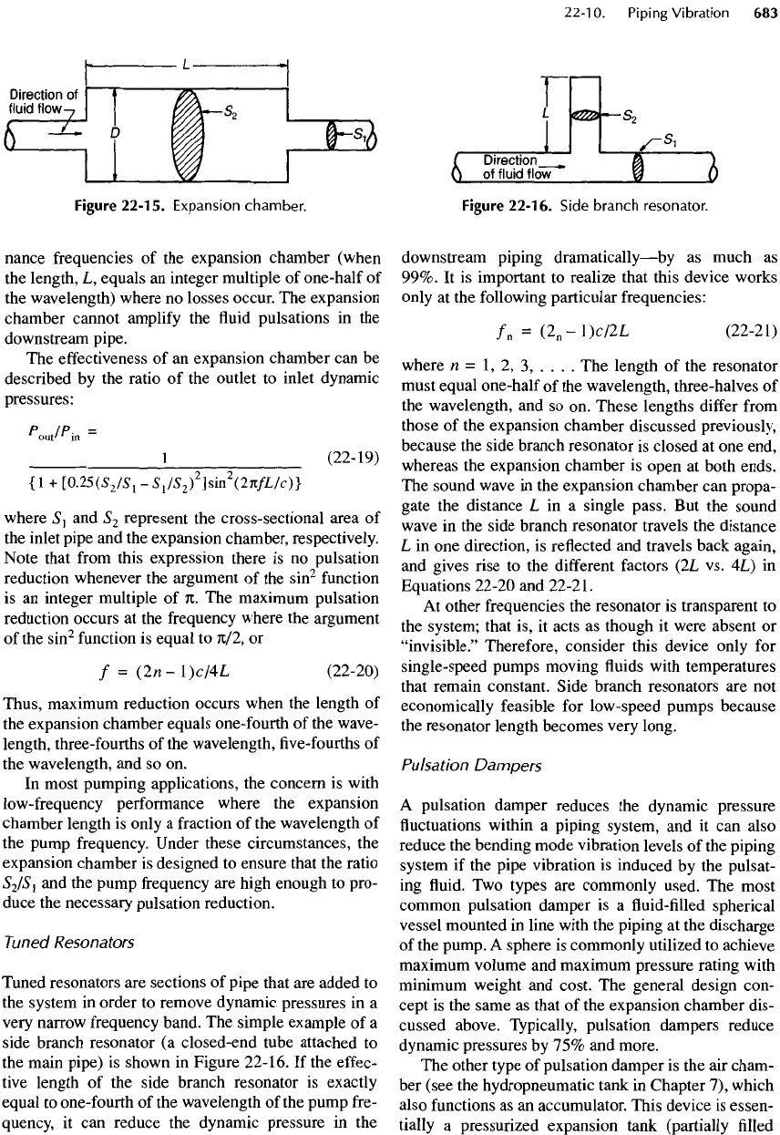
Figure
22-15.
Expansion
chamber.
nance frequencies
of the
expansion chamber (when
the
length,
L,
equals
an
integer multiple
of
one-half
of
the
wavelength) where
no
losses occur.
The
expansion
chamber cannot
amplify
the fluid
pulsations
in the
downstream
pipe.
The
effectiveness
of an
expansion chamber
can be
described
by the
ratio
of the
outlet
to
inlet dynamic
pressures:
P
IP-
=
1
out
M
m
1
(22-19)
{I
+
[0.25(S
2
IS
1
-
S
1
IS
2
)
2
^m
2
VKfLIc)]
where
S
1
and
S
2
represent
the
cross-sectional area
of
the
inlet
pipe
and the
expansion chamber,
respectively.
Note
that
from
this expression there
is no
pulsation
reduction whenever
the
argument
of the
sin
2
function
is
an
integer multiple
of
n.
The
maximum pulsation
reduction occurs
at the
frequency
where
the
argument
of
the
sin
2
function
is
equal
to
71/2,
or
/ =
(2n-l)c/4L
(22-20)
Thus, maximum reduction occurs when
the
length
of
the
expansion chamber equals one-fourth
of the
wave-
length,
three-fourths
of the
wavelength,
five-fourths of
the
wavelength,
and so on.
In
most pumping applications,
the
concern
is
with
low-frequency
performance where
the
expansion
chamber length
is
only
a
fraction
of the
wavelength
of
the
pump
frequency.
Under these circumstances,
the
expansion chamber
is
designed
to
ensure that
the
ratio
S
2
IS
1
and the
pump
frequency
are
high enough
to
pro-
duce
the
necessary pulsation reduction.
Tuned
Resonators
Tuned resonators
are
sections
of
pipe that
are
added
to
the
system
in
order
to
remove dynamic pressures
in a
very
narrow
frequency
band.
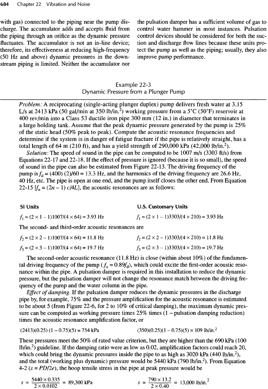
The
simple example
of a
side branch resonator
(a
closed-end tube attached
to
the
main pipe)
is
shown
in
Figure 22-16.
If the
effec-
tive
length
of the
side branch resonator
is
exactly
equal
to
one-fourth
of the
wavelength
of the
pump fre-
quency,
it can
reduce
the
dynamic pressure
in the
Figure
22-16.
Side
branch
resonator.
downstream
piping
dramatically
—
by
as
much
as
99%.
It is
important
to
realize
that this device works
only
at the
following particular frequencies:
/
n
=
(2
n
-l)c/2L
(22-21)
where
n =
1,
2, 3, . . . . The
length
of the
resonator
must
equal
one
-half
of the
wavelength, three-halves
of
the
wavelength,
and so on.
These
lengths
differ
from
those
of the
expansion chamber discussed previously,
because
the
side branch resonator
is
closed
at one
end,
whereas
the
expansion chamber
is
open
at
both ends.
The
sound wave
in the
expansion chamber
can
propa-
gate
the
distance
L in a
single pass.
But the
sound
wave
in the
side branch resonator travels
the
distance
L in one
direction,
is
reflected
and
travels back again,
and
gives rise
to the
different
factors
(2L
vs.
4L)
in
Equations 22-20
and
22-21.
At
other frequencies
the
resonator
is
transparent
to
the
system; that
is, it
acts
as
though
it
were absent
or
"invisible."
Therefore, consider this device only
for
single-
speed
pumps moving
fluids
with temperatures
that
remain constant. Side branch resonators
are not
economically feasible
for
low-speed pumps because
the
resonator length becomes very long.
Pulsation Dampers
A
pulsation damper reduces
the
dynamic pressure
fluctuations
within
a
piping system,
and it can
also
reduce
the
bending mode vibration levels
of the
piping
system
if the
pipe
vibration
is
induced
by the
pulsat-
ing
fluid. Two
types
are
commonly used.
The
most
common pulsation damper
is a fluid-filled
spherical
vessel mounted
in
line with
the
piping
at the
discharge
of
the
pump.
A
sphere
is
commonly utilized
to
achieve
maximum
volume
and
maximum pressure rating with
minimum
weight
and
cost.
The
general design con-
cept
is the
same
as
that
of the
expansion chamber dis-
cussed above. Typically, pulsation dampers reduce
dynamic pressures
by 75% and
more.
The
other type
of
pulsation damper
is the air
cham-
ber
(see
the
hydropneumatic tank
in
Chapter
7),
which
also
functions
as an
accumulator. This device
is
essen-
tially
a
pressurized expansion tank (partially
filled
with
gas) connected
to the
piping near
the
pump dis-
charge.
The
accumulator adds
and
accepts
fluid
from
the
piping through
an
orifice
as the
dynamic pressure
fluctuates. The
accumulator
is not an
in-line device;
therefore,
its
effectiveness
at
reducing high-frequency
(50 Hz and
above) dynamic pressures
in the
down-
stream
piping
is
limited. Neither
the
accumulator
nor
the
pulsation damper
has a
sufficient
volume
of gas to
control water hammer
in
most instances. Pulsation
control devices should
be
considered
for
both
the
suc-
tion
and
discharge
flow
lines because these units pro-
tect
the
pump
as
well
as the
piping; usually, they also
improve pump performance.
Example
22-3
Dynamic
Pressure
from
a
Plunger
Pump
Problem:
A
reciprocating (single-acting plunger duplex) pump delivers
fresh
water
at
3.15
L/s at
2413
kPa (50
gal/min
at 350
lb/in.
2
)
working pressure
from
a
5
0
C
(5O
0
F)
reservoir
at
400
rev/min
into
a
Class
53
ductile iron pipe
300 mm (12
in.)
in
diameter that terminates
in
a
large holding tank. Assume that
the
peak dynamic pressure generated
by the
pump
is 25%
of
the
static head (50% peak
to
peak). Compute
the
acoustic resonance frequencies
and
determine
if the
system
is in
danger
of
fatigue
fracture
if the
pipe
is
relatively straight,
has a
total length
of 64 m
(210 ft),
and has a
yield strength
of
290,000
kPa
(42,000
lb/in.
2
).
Solution:
The
speed
of
sound
in the
pipe
can be
computed
to be
1007
m/s
(3303 ft/s)
from
Equations 22-17
and
22-18.
If the
effect
of
pressure
is
ignored (because
it is so
small),
the
speed
of
sound
in the
pipe
can
also
be
estimated
from
Figure
22-13.
The
driving frequency
of the
pump
is/
d
=
(400) (2)/60
=
13.3
Hz, and the
harmonics
of the
driving
frequency
are
26.6
Hz,
40 Hz,
etc.
The
pipe
is
open
at one
end,
and the
pump itself closes
the
other end. From Equation
22-15
\f
n
=
(2n-l)
c/4L],
the
acoustic resonances
are as
follows:
Sl
Units
U.S.
Customary
Units
/!
=
(2x1-
l)1007/(4
x 64) =
3.93
Hz
/i
= (2 x 1 -
l)3303/(4
x
210)
=
3.93
Hz
The
second-
and
third-order acoustic resonances
are
/
2
= (2 x 2 -
l)1007/(4
x 64) =
11.8
Hz
/
2
= (2 x 2 -
1)33037(4
x
210)
=
11.8
Hz
/
3
=
(2 x 3 -
1)10077(4
x 64) =
19.7
Hz
/
3
= (2 x 3 -
1)33037(4
x
210)
=
19.7
Hz
The
second-order acoustic resonance
(11.8
Hz) is
close (within about 10%)
of the
fundamen-
tal
driving
frequency
of the
pump
(/
0
=
0.89/
d
),
which could excite
the first-order
acoustic reso-
nance within
the
pipe.
A
pulsation damper
is
required
in
this installation
to
reduce
the
dynamic
pressure,
but the
pulsation damper will
not
change
the
resonance match between
the
driving fre-
quency
of the
pump
and the
water column
in the
pipe.
Effect
of
damping.
If the
pulsation damper reduces
the
dynamic pressures
in the
discharge
pipe
by, for
example,
75% and the
pressure amplification
for the
acoustic resonance
is
estimated
to be
about
5
(from
Figure 22-6,
for 2 to 10% of
critical damping),
the
maximum dynamic pres-
sure
can be
computed
as
working pressure times
25%
times
(1 -
pulsation damping reduction)
times
the
acoustic resonance
amplification
factor,
or
(2413)(0.25)
(1 -
0.75X5)
= 754 kPa
(350)(0.25)(1
-
0.75)(5)
= 109
lb/in.
2
These pressures meet
the 50% of
rated value criterion,
but
they
are
higher than
the 690 kPa
(100
lb/in.
2
)
guideline.
If the
damping ratio were
as low as
0.02, amplification factors could reach
20,
which
could bring
the
dynamic pressures inside
the
pipe
to as
high
as
3020
kPa
(440
lb/in.
2
),
and
the
total (working plus dynamic) pressure would
be
5440
kPa
(790
lb/in.
2
).
From Equation
4-2 (s =
PD/2e),
the
hoop tensile stress
in the
pipe
at
peak pressure would
be
5440
x
0.335
Q0
ann
,
D
790 x
13.2
t
a
nnn
„,.
2
5
=
2x0.0102
=
89
'
3
°
0kPa
S
=
-2^04^
=
13
'
0001b
/
in
-
22-11.
Vibration
of
Drive
Shafts
Drive
shaft
vibration
is a
complicated phenomenon
composed
of two
independent
forms
of
vibration
—
translational
and
torsional.
The
approximation meth-
ods
presented here
are
intended
to
provide only
(1) a
reasonable idea
of
safety
margins
and (2)
sufficient
background
for
pumping station designers
to
judge
properly
the
results presented
by the
shaft,
engine,
or
(usually)
pump manufacturer,
who
should
be
respon-
sible
for the
design
of the
entire rotating system (see
Appendix
C).
Translational Vibration
Translational vibration (which
is
sometimes
called
"lateral vibration") involves
the
oscillatory motion
of
the
drive
shaft
about
its
ideal
"at
rest"
centerline.
The
shaft
has
natural frequencies
and
assumes related
mode shapes just
as
piping systems
do, and all of the
equations
and
analyses
on
piping vibration
in
Section
22-10
also apply
to
drive
shafts.
Drive
shafts
are
much more sensitive
to
vibration
problems than
are
piping systems, because
the
drive
shaft
rotates
and any
unbalance
in the
drive
shaft
or
misalignment
in the
coupling causes
the
shaft
to
vibrate
or
deflect
laterally, which results
in
"shaft
whip." This vibration
is
very
difficult
to
measure
directly,
but it can be
measured indirectly
via
sensors
at
the
shaft
support bearings. Avoiding rotational
speeds that match
or
excite
the
natural
or
resonance
frequencies
of the
translational vibration
of the
drive
shaft
is
imperative.
These
speeds
are
called
"critical
speeds,"
and
they
are
determined entirely
by the
phys-
ical properties
of the
shaft.
If
the
drive
shaft
is
assumed
to be a
uniform,
straight,
steel tube with
a
circular cross-section
(or a
solid cylinder
if ID = O),
Equation
22-11
can be
rear-
ranged into
a
somewhat simpler
form
for a
quick eval-
uation
of the
lowest natural frequency.
/!
=
-|
J(OD)
2
+
(ID)
2
2
(22-22)
p
=
iii
H
871A/P
where/j
is the first-order
shaft
resonance
in
hertz,
OD
is the
outer diameter
of the
shaft
in
millimeters
(inches),
ID is the
inner diameter
of the
shaft
in
milli-
meters (inches),
L is the
effective
length
of the
shaft
in
millimeters (inches),
and P is
2.03
x
10
6
mm/s
in SI
units
for
universal (pinned) joint couplings
or
4.6
xlO
6
mm/s
for
direct-coupled
(fixed)
shafts.
In
U.S. customary units,
p
is 7.9 x
10
4
in./s
for
pinned
joint couplings
and
1.79
x
10
6
in./s
for fixed
shafts.
A
drive
shaft
also
has
other modes
of
lateral vibration
at
higher frequencies,
but
these
are
usually
not
problem
frequencies
because
the
rotational speed
of
shafts
is
usually
below
the first
resonance.
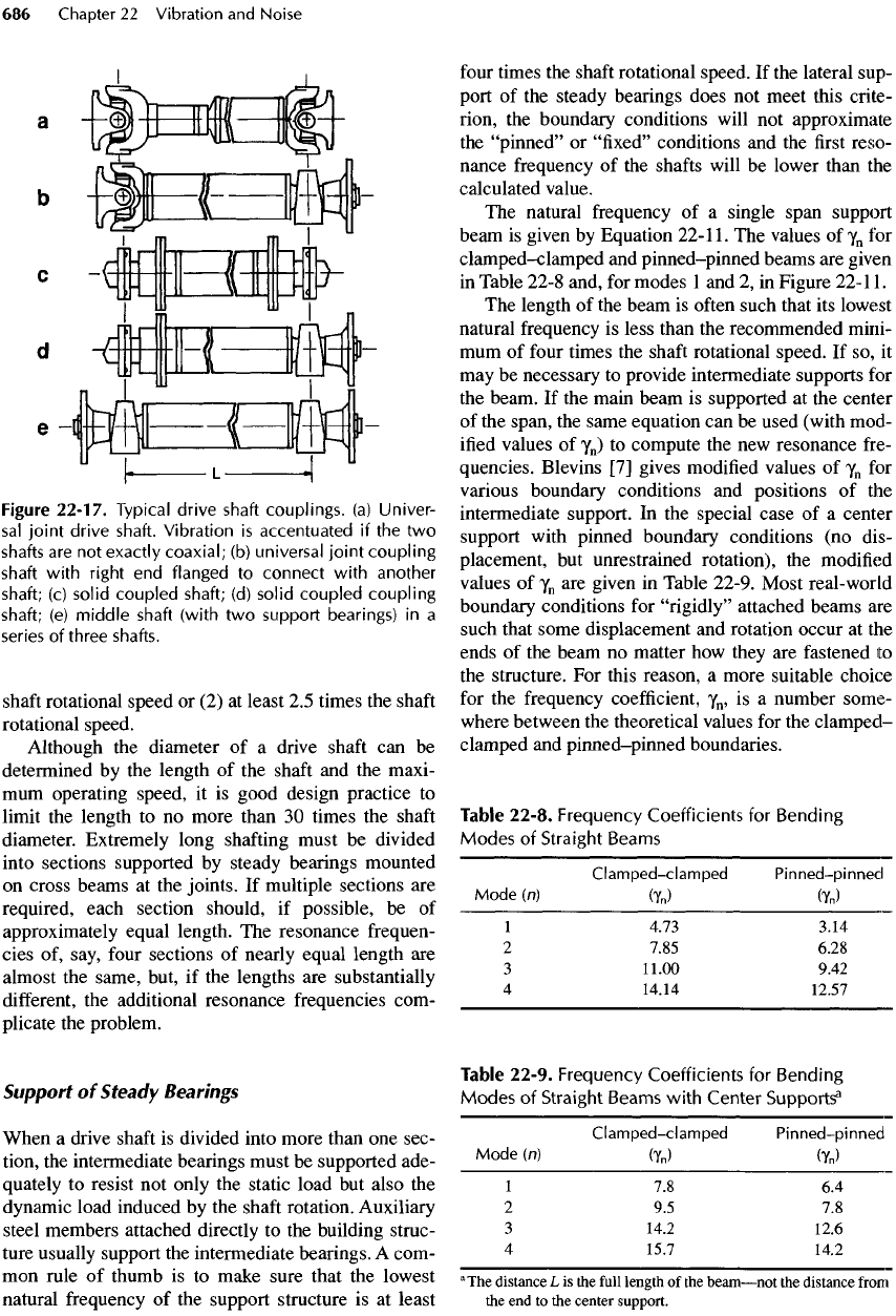
When using Equation 22-22
to
compute
the
reso-
nance frequencies
of the
drive
shaft,
the
length,
L, of
the
shaft
should
be
measured
from
the
center
of the
universal joints
on
both
the
driving
and the
driven
ends (see Figure
22-17).
Steady bearings
may be
used
as
intermediate supports
to
reduce
L and
increase
the
resonance frequency
out of the
region
of
concern.
To
avoid
operating
at a
critical speed,
the
drive
shaft
should
be
designed
to
ensure that
the
highest rota-
tional
shaft
speed
is
less than
75% of the
lowest natu-
ral
frequency. Furthermore, rotational speeds that
are
nearly equal
to
one-half
of the
lowest bending mode
frequency
of the
shaft
should
be
avoided because sec-
ondary moments
from
universal joints produce
an
excitation frequency
at
twice
the
shaft
speed. Combin-
ing
these
two
criteria gives
two
acceptable ranges
for
the
lowest
shaft
frequency:
(1) 1.4 to
1.6
times
the
This seems
safe
enough,
but the
maximum yield strength
of
290,000
kPa
(42,000
lb/in.
2
)
is
applicable only
to
static stress levels. Dynamic stress levels must
be
substantially lower
to
avoid
fatigue
failure.
Changing
operating speed.
In
addition
to the
pulsation damper,
the
operating speed
of the
pump
should
be
changed
to
avoid operation near
the
acoustic resonance frequencies and, thus,
reduce
the
internal dynamic pressure.
A
suitable choice might
be a
smaller duplex pump run-
ning
at 480
rev/min, which would yield driving frequencies
of 16 Hz, 32 Hz,
etc.,
and
would
result
in an
estimated pressure amplification
of
less than about
2.0 for all
values
of the
damping
ratio (see Figure 22-6)
for/
d
/y
o
=
16/11.8
=
1.356.
The
maximum dynamic pressure
at the
driv-
ing
frequency
of the
pump would then
be
(2420)(0.25)(1
-
0.75)(2)
= 302 kPa (44
lb/in.
2
),
which
is
safe
by
both
criteria.
Figure
22-17.
Typical
drive
shaft
couplings,
(a)
Univer-
sal
joint
drive
shaft.
Vibration
is
accentuated
if the two
shafts
are not
exactly
coaxial;
(b)
universal
joint
coupling
shaft
with
right
end
flanged
to
connect
with
another
shaft;
(c)
solid
coupled
shaft;
(d)
solid
coupled
coupling
shaft;
(e)
middle
shaft
(with
two
support
bearings)
in a
series
of
three
shafts.
shaft
rotational speed
or (2) at
least
2.5
times
the
shaft
rotational speed.
Although
the
diameter
of a
drive
shaft
can be
determined
by the
length
of the
shaft
and the
maxi-
mum
operating speed,
it is
good design practice
to
limit
the
length
to no
more than
30
times
the
shaft
diameter. Extremely long
shafting
must
be
divided
into sections supported
by
steady bearings mounted
on
cross beams
at the
joints.
If
multiple sections
are
required, each section should,
if
possible,
be of
approximately equal length.
The
resonance
frequen-
cies
of,
say,
four
sections
of
nearly equal length
are
almost
the
same, but,
if the
lengths
are
substantially
different,
the
additional resonance frequencies com-
plicate
the
problem.
Support
of
Steady
Bearings
When
a
drive
shaft
is
divided into more than
one
sec-
tion,
the
intermediate bearings must
be
supported ade-
quately
to
resist
not
only
the
static load
but
also
the
dynamic
load induced
by the
shaft
rotation. Auxiliary
steel members attached directly
to the
building struc-
ture usually support
the
intermediate
bearings.
A
com-
mon
rule
of
thumb
is to
make sure that
the
lowest
natural
frequency
of the
support structure
is at
least
four
times
the
shaft
rotational
speed.
If the
lateral sup-
port
of the
steady bearings
does
not
meet this crite-
rion,
the
boundary conditions will
not
approximate
the
"pinned"
or
"fixed" conditions
and the first
reso-
nance frequency
of the
shafts
will
be
lower than
the
calculated value.
The
natural frequency
of a
single span support
beam
is
given
by
Equation
22-1
1
.
The
values
of
y
n
for
clamped-clamped
and
pinned-pinned
beams
are
given
in
Table 22-8 and,
for
modes
1 and 2, in
Figure
22-1
1.
The
length
of the
beam
is
often
such that
its
lowest
natural
frequency
is
less than
the
recommended mini-
mum
of
four
times
the
shaft
rotational speed.
If so, it
may
be
necessary
to
provide intermediate supports
for
the
beam.
If the
main beam
is
supported
at the
center
of
the
span,
the
same equation
can be
used (with mod-
ified
values
of
y
n
)
to
compute
the new
resonance fre-
quencies. Blevins
[7]
gives
modified
values
of
y
n
for
various boundary conditions
and
positions
of the
intermediate support.
In the
special case
of a
center
support with pinned boundary conditions
(no
dis-
placement,
but
unrestrained rotation),
the
modified
values
of
y
n
are
given
in
Table 22-9. Most real-world
boundary
conditions
for
"rigidly"
attached beams
are
such that some displacement
and
rotation occur
at the
ends
of the
beam
no
matter
how
they
are
fastened
to
the
structure.
For
this reason,
a
more suitable choice
for
the
frequency
coefficient,
y
n
,
is a
number some-
where between
the
theoretical values
for the
clamped-
clamped
and
pinned-pinned
boundaries.
Table
22-8.
Frequency
Coefficients
for
Bending
Modes
of
Straight
Beams
Clamped-clamped
Pinned-pinned
Mode
(n)
(y
n
)
(y
n
)
1
4.73 3.14
2
7.85 6.28
3
11.00 9.42
4
14.14 12.57
Table
22-9.
Frequency
Coefficients
for
Bending
Modes
of
Straight
Beams
with
Center
Supports?
Clamped-clamped
Pinned-pinned
Mode
(n)
(y
n
)
(y
n
)
1
7.8 6.4
2
9.5 7.8
3
14.2 12.6
4
15.7 14.2
a
The
distance
L is the
full
length
of the
beam
—
not
the
distance
from
the
end to the
center
support.
Torsional
Vibration
Torsional vibration problems occur less frequently
than
translational vibration problems,
but
they
can be
just
as
troublesome
and
sometimes catastrophic.
Because they
are not
detected
by our
senses until
fail-
ure
occurs,
it is
important
to
select
equipment
compo-
nents that preclude this possibility.
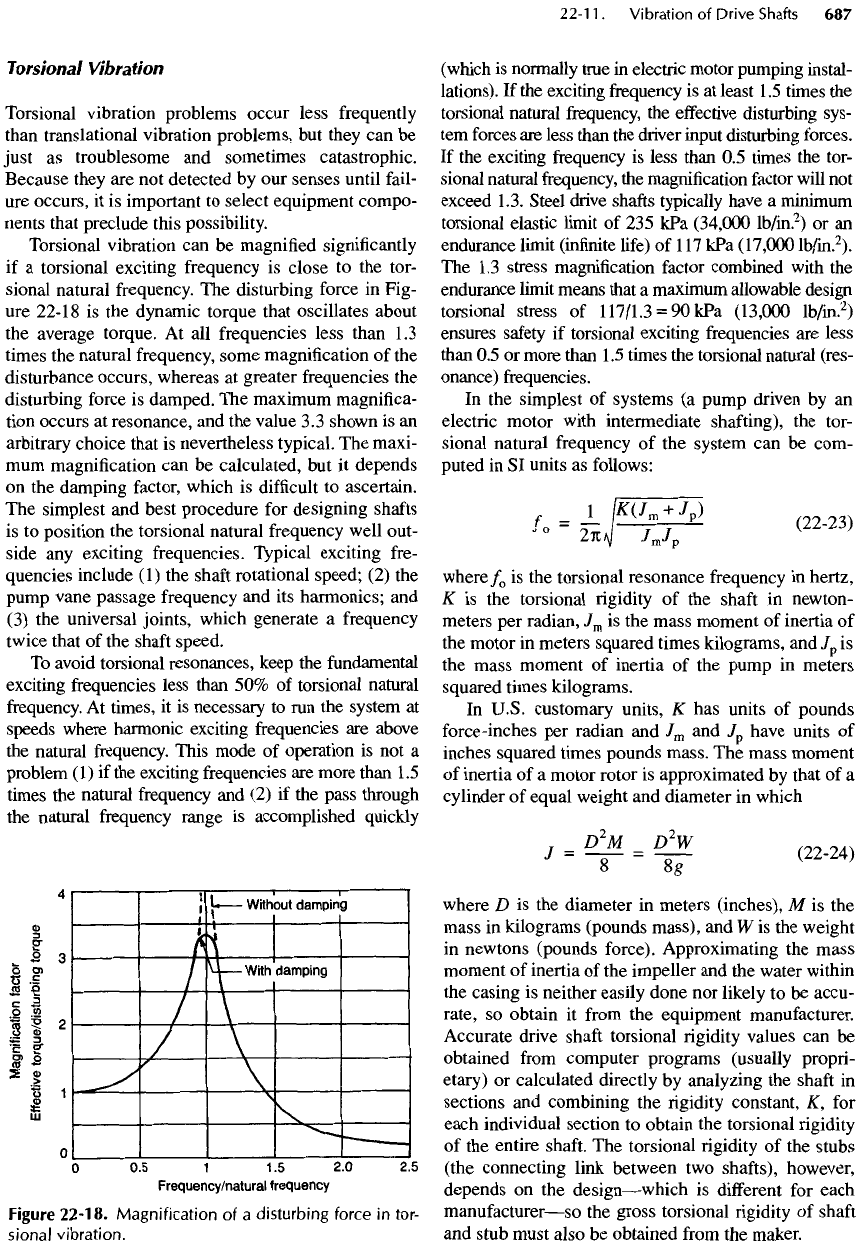
Torsional vibration
can be
magnified significantly
if
a
torsional exciting frequency
is
close
to the
tor-
sional natural frequency.
The
disturbing force
in
Fig-
ure
22-18
is the
dynamic torque that oscillates about
the
average torque.
At all
frequencies less than
1.3
times
the
natural frequency, some magnification
of the
disturbance
occurs,
whereas
at
greater
frequencies
the
disturbing force
is
damped.
The
maximum magnifica-
tion occurs
at
resonance,
and the
value
3.3
shown
is an
arbitrary
choice that
is
nevertheless typical.
The
maxi-
mum
magnification
can be
calculated,
but it
depends
on the
damping factor, which
is
difficult
to
ascertain.
The
simplest
and
best procedure
for
designing
shafts
is
to
position
the
torsional natural frequency well
out-
side
any
exciting frequencies. Typical exciting
fre-
quencies include
(1) the
shaft
rotational
speed;
(2) the
pump
vane passage frequency
and its
harmonics;
and
(3) the
universal joints, which generate
a
frequency
twice
that
of the
shaft
speed.
To
avoid torsional resonances, keep
the
fundamental
exciting
frequencies less than
50% of
torsional natural
frequency.
At
times,
it is
necessary
to run the
system
at
speeds where harmonic exciting frequencies
are
above
the
natural frequency. This mode
of
operation
is not a
problem
(1) if the
exciting frequencies
are
more than
1.5
times
the
natural
frequency
and (2) if the
pass through
the
natural
frequency
range
is
accomplished quickly
Figure
22-18.
Magnification
of a
disturbing
force
in
tor-
sional
vibration.
(which
is
normally true
in
electric motor pumping instal-
lations).
If the
exciting
frequency
is at
least
1.5
times
the
torsional natural frequency,
the
effective
disturbing
sys-
tem
forces
are
less than
the
driver input disturbing forces.
If
the
exciting frequency
is
less than
0.5
times
the
tor-
sional
natural frequency,
the
magnification
factor
will
not
exceed
1.3.
Steel
drive shafts typically have
a
minimum
torsional elastic limit
of 235
kPa
(34,000
lb/in.
2
)
or an
endurance
limit (infinite
life)
of
1
17
kPa
(17,000
lb/in.
2
).
The 1.3
stress magnification
factor
combined with
the
endurance limit means that
a
maximum allowable design
torsional stress
of
117/1.3
=
9OkPa
(13,000
lb/in.
2
)
ensures
safety
if
torsional exciting frequencies
are
less
than
0.5 or
more than
1.5
times
the
torsional natural
(res-
onance) frequencies.
In the
simplest
of
systems
(a
pump driven
by an
electric
motor with intermediate shafting),
the
tor-
sional natural frequency
of the
system
can be
com-
puted
in SI
units
as
follows:
=
J
_/w
m+
/
P
)
/0
1K>1
J
m
j
p
(2223)
where
/
0
is the
torsional resonance frequency
in
hertz,
K
is the
torsional
rigidity of the
shaft
in
newton-
meters
per
radian,
J
m
is the
mass moment
of
inertia
of
the
motor
in
meters squared times kilograms,
and/
p
is
the
mass moment
of
inertia
of the
pump
in
meters
squared times kilograms.
In
U.S.
customary units,
K has
units
of
pounds
force-inches
per
radian
and
J
m
and
/
p
have units
of
inches
squared times pounds mass.
The
mass moment
of
inertia
of a
motor rotor
is
approximated
by
that
of a
cylinder
of
equal weight
and
diameter
in
which
'
-
1"
-
f
where
D is the
diameter
in
meters (inches),
M is the
mass
in
kilograms (pounds mass),
and W is the
weight
in
newtons (pounds force). Approximating
the
mass
moment
of
inertia
of the
impeller
and the
water within
the
casing
is
neither easily done
nor
likely
to be
accu-
rate,
so
obtain
it
from
the
equipment manufacturer.
Accurate drive
shaft
torsional
rigidity
values
can be
obtained
from
computer
programs
(usually
propri-
etary)
or
calculated directly
by
analyzing
the
shaft
in
sections
and
combining
the
rigidity constant,
K,
for
each individual
section
to
obtain
the
torsional
rigidity
of
the
entire
shaft.
The
torsional
rigidity
of the
stubs
(the
connecting link between
two
shafts),
however,
depends
on the
design
—
which
is
different
for
each
manufacturer
—
so
the
gross torsional
rigidity of
shaft
and
stub must
also
be
obtained
from
the
maker.