Pumping Station Desing - Second Edition by Robert L. Sanks, George Tchobahoglous, Garr M. Jones
Подождите немного. Документ загружается.

The
torsional rigidity
of a
uniform, hollow, circular
shaft
of
length
L is
expressed
as
K
=
^[
(OD)4
~
(/D)4
]
(22
~
25)
where
G is the
modulus
of
elasticity
of
steel
in
shear,
which
is
82.7
x
10
9
Pa (12 x
10
6
lb/in.
2
),
and
linear
dimensions
are in
meters (inches).
For
solid shafting,
use ID = O. If a
shaft
is
made
up of two or
more sec-
tions
of
shafting
with
different
physical properties,
the
torsional rigidity
of the
entire
shaft
can be
com-
puted
from
the
torsional rigidity
of the
individual
sections
as
K
-
l
(22-26)
£/=i(l/^i)
Example
22-4
Torsional
Vibration
in a
Shaft
Problem:
A
two-vane, end-suction centrifugal pump
is
driven
by a
75-kW
(100-hp),
variable-
speed, direct-drive electric motor
at
speeds varying
from
840 to
1200
rev/min
(14
to 20
Hz).
The
power
shafting
is a
universal joint,
3.353-m
(132-in.)
drive
shaft
(see Figure 22-17a) with 2.67
m
(105 in.)
of
101.6-mm
(4-in.)
OD
tubing
and a
wall thickness
of
2.108
mm
(0.083
in.).
The
manufacturer
gives
the
mass moment
of
inertia
as
J
p
=
1.729
kg •
m
2
(15.3
lbm
•
in.
2
)
and
J
m
-
1.345
kg •
m
2
(11.9
lbm •
in.
2
).
The
torsional
rigidity
of the
drive
shaft
stubs (excluding
the
tubing
between
the
stubs)
is
given
as
31,400
N •
m/rad (277,802
Ib
•
in./rad).
Evaluate
the
translational
and
torsional resonances
of the
shafting
and
determine
if the
sys-
tem
is
within acceptable guidelines.
If
intermediate support bearings
are
required, size
the
struc-
tural
members within recommended guidelines.
Solution:
Lateral
resonance.
The
rotating frequencies
of the
shaft
are
14-20
Hz
(fundamental)
and
28^0
Hz
(second harmonic
and
pump vane passage frequency). From Equation 22-22,
the first-
order lateral resonance
of the
shaft
is
Sl
Units
U.S.
Customary
Units
A
=
2^xl0.
6
V(1016)
2
+
(97384)
2
=
IWX^
4
J
2+
(3JJ34)
2
(3353)
(132)
=
25.4
Hz =
25.4
Hz
The
maximum
shaft
speed
is 20 Hz,
which
is 78% of the
fundamental resonance
of the
shaft.
Ideally,
the
shaft
speed should
not
exceed
75% of the first
resonance,
so
this
shaft
speed
is a
marginal
condition.
Torsional
resonance.
To
compute
the
torsional resonance frequency,
first
determine
the
shaft
rigidity,
K^
from
Equation 22-25.
71(82.7
x
10
9
)[(0.1016)
4
-
(0.097384)
4
]
7E(12.0
x
10
6
)[(4)
4
-
(3.834)
4
~|
^tubing
=
32(2.67)
^tubing
=
32(105)
=
50,526
N •
m/rad
=
447,935
Ib
•
in./rad
From Equation 22-26:
^shaftmg
=
[(31,40O)-
1
+
(50,526)-']
K
shafting
=
[(277,
802)'
1
+
(447,935)']
=
19,368
N
•
m/rad
=
171,463
Ib
•
in./rad
Determine
the
torsional resonance frequency
from
Equation 22-23:
22-12.
Vibration
of
Structures
Pumping
station equipment
can
cause structures
to
vibrate
at
levels exceeding normally acceptable crite-
ria
[23],
particularly
if the
equipment
is
operating
at a
speed that matches
one of the
low-order resonance
frequencies
of the
structure.
In the
design phase,
it is
too
difficult
to
predict accurately
the
natural frequen-
cies
of
supporting structures (building
floor
slabs,
pedestals, etc.),
but
there
are
some simple calculations
that
can be
made
to
determine whether
a
potential
problem exists.
The
lowest natural frequency
of a
supporting struc-
ture
can be
estimated
from
basic information concern-
ing
the
static load-carrying capability
of the
structure.
This information
is
often
available directly
from
the
structural
engineer. Assuming that
the
structural mem-
ber
undergoes
a
static deflection directly proportional
to the
dead load
of the
equipment,
the
dynamic behav-
ior of the
structural member
is
similar
to
that
of a
steel
spring (for small deflections).
If the
maximum static
deflection
of the
structure (due
to the
weight
of the
equipment),
d,
is
expressed
in
millimeters,
the
natural
frequency
of the
structure
in
hertz
is
approximately
/
0
=
15.8
JlJd
(22-27a)
If
d is
expressed
in
inches,
/
0
=
3.
13
TlA/
(22-27b)
This expression
is
approximately valid (±25%) only
when
d <
L/500,
where
L is the
smallest cross dimen-
sion (width
or
height)
of the
structure,
but
this condi-
tion should
be
satisfied
by
most pumping station
Sl
Units
U.S.
Customary
Units
,
=
J_
/(19,368)(1.729
+1.345)
f
=
JL
/(171,463)(
15.3
+
11.9)
/0
2n*j
(1.729)(1.345)
/0
2rcA/
(15.3)(11.9)
=
25.4
Hz =
25.4
Hz
This
is
below
the
recommended minimum
of
1.5
times
20 Hz
(the highest
shaft
speed)
and is,
thus,
unacceptable.
Increasing
the
shaft
OD to 127 mm (5
in.)
and the ID to 120 mm
(4.72 in.) would increase
the
first-order
lateral resonance
to
31.6
Hz and the
torsional resonance
to
29.7
Hz.
This
modifi-
cation
would nearly meet
the
torsional criteria,
but the
lateral resonance
may be
excited
by the
second harmonic
of the
shaft
speed
at 948
rev/min
(or
15.8 Hz).
An
alternative solution would
be to
retain
the
original
shaft
diameters
and
split
the
shaft
into
two
equal sections with
an
inter-
mediate support bearing.
The
fundamental lateral
shaft
resonance then becomes 101.8
Hz,
which
is
acceptable,
because
f
{
/f
d
=
5.09.
The new
torsional spring constant
of
each section
is
101,052
N •
m/rad, which yields
a
total spring constant
of
23,956
N •
m/rad
and a
torsional reso-
nance
of
58.2
Hz,
which
is
also acceptable.
If
the
intermediate
shaft
bearing
is
supported
by a
section
of
steel angle 20.3
cm x
20.3
cm x
1.9
cm
(8
in. x 8 in. x
3
/
4
in.) thick
that
weighs
568 N/m
(38.9
Ib/ft),
has a
moment
of
inertia about both axes
of
2.9 x
10~
5
m
4
(69.7
in.
4
),
and
spans
6.10
m (20 ft)
with
fully
restrained
end
points,
the
fundamental
res-
onance
frequency
of
this beam
is, from
Equation
22-11
and
Figure
22-11,
=
(4.73)
2
/(2xl0
11
)(2.9xlO"
5
)(9.81)
=
(4.73)
2
/(29
x
1Q
6
)(69.7)(386)
1
=
27C(610)
2A
/
568
!
=
27T(240)
2A
/
<
38
-
9
/
12
)
=
30.3
Hz =
30.3
Hz
The
computed resonance frequency
of the
beam
is
insufficient
to
meet
the
conservative crite-
rion
of
four
times
the
maximum operating speed,
but if a
center support (with pinned boundary
conditions) were added
to
this beam,
the
lowest beam frequency would
be
increased
by a
factor
of
(7.85/4.73)
2
=
2.75.
The
fundamental beam frequency would
be
increased
to
2.75
x
30.4
=
83.6
Hz,
which
is
4.18
times
the
maximum operating speed
of 20 Hz and
does meet
the
recommended
criterion.
If the
bearing were
to be
located
at the
center
of the
main beam (where
the
center support
beam
is
attached), this problem would
not
arise because
the
vibrating force would
be
applied
at a
node
of
this
first
beam resonance,
and it
would
not be
excited.
buildings.
Although
the
correlation between
the
vibra-
tion
of a
point mass
on a
spring
and the
distributed
mass
of a
concrete
floor may
seem unreasonable,
the
two
systems vibrate
at
nearly
the
same frequency,
because
the use of
deflection
in
Equation 22-27 tends
to
compensate
for the
differences between
the two
systems.
Much
more accurate determinations
of
structural
resonance frequencies
can be
obtained
by
modal anal-
ysis
and
other more elaborate techniques,
but
these
methods
are
usually beyond
the
scope
of
most pump-
ing
station projects. Determining
the
maximum struc-
tural
deflection
caused
by the
static weight
of the
equipment
is
sometimes complicated,
but
approxima-
tions
that provide
an
upper limit
for d are
usually ade-
quate.
Practical solutions
lie in the
close cooperation
between
the
project leader
and the
structural engineer,
which
illustrates
why a
project leader must
be
much
more than
an
administrator
who
assigns tasks
and
responsibilities
to
others.
Ideally,
vibrating equipment should
not
operate
at
a
rotational speed near
the
fundamental
frequency
of
the
supporting structure. Although problems
are
unlikely
if the
rotating speed
is 5%
greater than
or 5%
less than
the
resonance frequency,
a 25%
safety
mar-
gin
on
each side
is
recommended.
Natural
frequencies
of a
variety
of
structural mem-
bers
are
given
by
Blevins
[7].
In
general,
the
natural
frequency
of any
structure
is
proportional
to the
square root
of the
composite moment
of
inertia,
/,
divided
by the
total mass
of the
system.
/o-77/M
(22-28)
Any
efforts
to
change
the
natural frequency
of an
existing system, therefore, should
be
devoted
to
these
two
parameters. Notice that doubling
the
mass
of the
system
(equipment plus structure) reduces
the
natural
frequency
by 29%
(1
-
V(X5)
if it is
assumed that
mass
can be
doubled with
no
change
in the
moment
of
inertia. However, structural modifications
usually
affect
both
M and /, so the
modifications should
be
evaluated
carefully
prior
to
making
the
change.
Example
22-5
Vibration
of a
Floor
Problem:
A
300-kVA
(400-hp)
variable-speed
induction motor (900
to
1200 rev/min)
is to be
mounted
on a
100-mm-
(4-in.-)thick housekeeping
pad
over
a
200-mm- (8-in.-) thick concrete
slab
that
is
continuously supported
by the
perimeter wall
as
well
as by a
concrete beam that
divides
the
slab
in the
center.
The
motor
is
mounted with
the
shaft
vertical
and is
rigidly bolted
to
the
housekeeping pad.
The
drive
shaft
penetrates
the floor
beside
the
beam
and in the
center
of
the
pad.
The
structural engineer estimates
the
static deflection
of the floor
slab (due
to the
weight
of the
motor)
to be 1 mm
(0.04
in.).
Evaluate
the
potential
for a floor
vibration problem
and
provide
a
solution
if
necessary.
Solution:
The
driving
frequency
range
of the
motor
is
15
to 20 Hz for the
fundamental
and
30 to 40 Hz for the
second harmonic. Note that because vibrating machinery produces excita-
tion
forces
in all
directions,
the
orientation
of the
motor
is of
little practical significance.
From Equation 22-27
the
estimated natural frequency
of the floor is as
follows:
Sl
Units
U.S. Customary
Units
/„=
15.8
Ji
=15.8
Hz
/„
=
3.13
JX
=
15.7
Hz
which
is in the
operating range
of the
pump's
fundamental frequency.
The
natural
frequency
of the floor
should
be at
least
25 Hz
(1.25 times
the
maximum
funda-
mental
driving
frequency
of 20
Hz). Solving
for d in
Equation
22-21,
the
maximum allowable
deflection
is
25 =
15.8
A 25 =
3.13
M
1
Vd
^d
d
= 0.4 mm d =
0.016
in.
This would require
a
reduction
of
more than
50%
from
the
original conditions,
and it
might
be
very
difficult
for the
structural engineer
to
design
for so
small
a
deflection.
As an
alternative,
22-13.
Noise
The
intent
of
this section
is to
provide project leaders
with
some elementary tools
to
evaluate
the
severity
of
sound
propagation through
the
air, including transmis-
sion
through barriers.
A
discussion
of
structure-borne
sound (i.e., structural vibrations resulting
in
subse-
quent
noise radiation
from
solid surfaces)
is of
little
importance
in
most pumping stations and, hence,
is
not
included. Heed OSHA regulations
and
local ordi-
nances,
as
explained
in
Section 22-6.
Outdoor
Sound
Propagation
Noise radiates
from
a
source
in all
directions,
and
sound
propagates
in air at a
nominal velocity
of 344
m/s
(1
130
ft/s)
at
2O
0
C
(7O
0
F).
The
actual velocity var-
ies
somewhat with temperature
and
barometric pres-
sure,
but for
practical purposes this dependence
can
usually
be
ignored.
The
intensity
of
sound decreases
with
the
square
of the
distance
from
a
source (much
like
the
intensity
of
light
from
a
light bulb)
as the
acoustical energy spreads
out
over
a
larger
and
larger
surface
area.
In
addition
to
this "spreading
loss"
there
is
also
a
slight loss
due to
atmospheric absorption
(conversion
of
acoustical energy into heat),
but
this
can
be
neglected
in
most applications.
The
sound pressure level,
L
p
,
at a
point
can be
expressed
as a
function
of the
distance
to the
source,
x,
and the
sound pressure level
from
the
source
at a
reference
distance,
X
0
,
in the
same direction. This
spreading
loss
can be
expressed
as
L
p
(x)
=
L
p
(x
0
)
+ 20
lo
glo
(x
J
X)
(22-29)
The
effects
of
partial
or
full
barriers,
the
reflections
from
surrounding surfaces,
and the
directivity
of the
source
are not
considered
in
Equation 22-29,
and in an
enclosed room
the
equation
may be
valid only within
a
few
feet
of the
source.
For an
outdoor source,
the
expression
may be
reasonably accurate
for
hundreds
of
meters provided that
(1)
there
are no
barriers
or
major
reflecting
surfaces (such
as
buildings)
and (2) the
direction
of the
reference measurement
is the
same
as
the
direction
of
interest.
In the
special case
of x =
2x
0
(where
the
location
of
interest
is
twice
as far
from
the
source
as the
reference position),
the
difference
in the
noise levels
at the two
positions
is 6 dB.
Thus, when-
ever
the
distance
to the
source
is
doubled,
the
sound
intensity
drops
by 6 dB.
Likewise, whenever
the
dis-
tance
to the
source
is
reduced
by
50%,
the
sound inten-
sity
increases
by 6 dB.
These
general rules
are
only
strictly valid
in a
free
field
(i.e.,
an
environment with-
out
reflective
or
absorptive surfaces),
but
they
are
approximately valid
in
many typical situations.
Indoor
Sound
Propagation
In
an
enclosed
or
partially enclosed room, noise radi-
ating
from
equipment
is
reflected
from
the
room
boundaries
and
builds
up to a
higher noise level than
if
the
equipment were located outside. This buildup
of
noise caused
by
acoustical energy being contained
within
the
room creates
a
"reverberant
area
or field" in
the
room.
The
reverberant
field
concept
is
illustrated
in
Fig-
ure
22-19,
where noise level
is
plotted
as a
function
of
distance
from
a
noise source.
In the
region near
the
source (the direct
field), the
noise level
falls
off at the
6 dB per
double distance rate because
the
acoustical
energy radiating directly
from
the
source overpowers
the
reverberant
field. As the
listener moves farther
from
the
source,
the
noise
level reaches
a
sound pres-
sure
level that
is
relatively constant.
It is
this region
that
is
called
the
reverberant
field. In SI
units,
the
noise level
in the
reverberant
field can be
approxi-
mated
by the
following expression:
consider reducing
the
natural frequency
of the floor so
that
the
lowest driving frequency
is
about
25%
above
the
natural frequency
of the floor.
This modification would require
a floor
frequency
of
15
Hz/1.25
= 12 Hz,
which (again
from
Equation 22-27) corresponds
to a
static deflection
of
d
=
!(15.8/12)
2
=
1.73
mm d =
0.04(15.8/12)
2
=
0.07
in.
By
directing
the
structural engineer
to
alter
the
supporting structure (decreasing
the
slab
thickness,
modifying
the
beam supports, etc.)
to
meet
the
desired static deflection,
the floor
res-
onance problem
can be
avoided.
It
should
be
noted that
the floor
would have other natural fre-
quencies higher than
the
fundamental frequency approximated
by
Equation 22-27,
and
these
natural
frequencies
may
become resonant with
the
higher harmonics
of the
pump. Evaluating
such
a
problem
is so
complex that
it is
beyond
the
scope
of
this chapter.
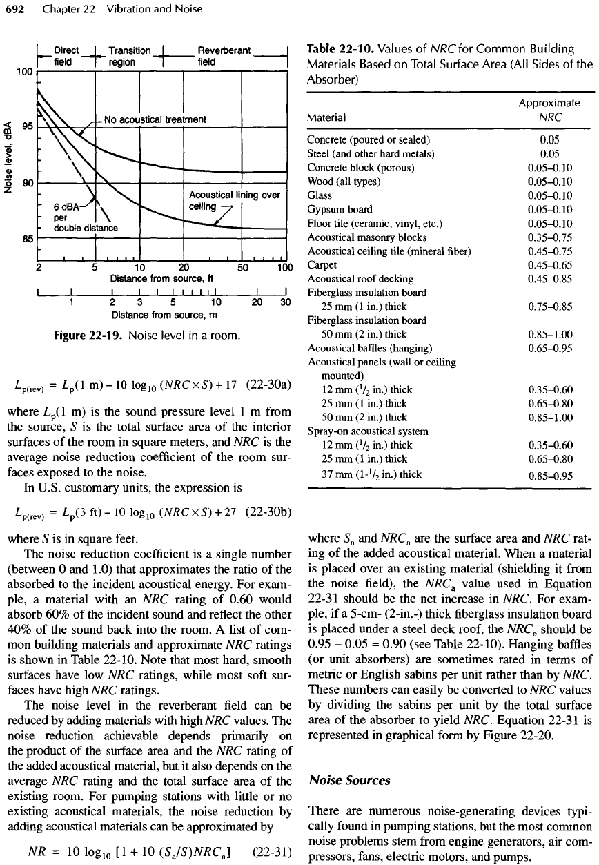
Figure
22-19.
Noise
level
in a
room.
L
p(
rev)
=
V
1
m)
~
10
10
^iO
(
NRC
x
S)
+ 17
(22-3Oa)
where
L
p
(l
m)
is the
sound pressure level
1
m
from
the
source,
S is the
total surface area
of the
interior
surfaces
of the
room
in
square meters,
and NRC is the
average
noise
reduction
coefficient
of the
room sur-
faces
exposed
to the
noise.
In
U.S. customary units,
the
expression
is
L
P
(rev)
=
V
3
ft
>
-
10
10
^iO
(
NRC
x
5) +
27
(22-3Ob)
where
S is in
square feet.
The
noise reduction
coefficient
is a
single number
(between
O and
1
.0)
that approximates
the
ratio
of the
absorbed
to the
incident acoustical energy.
For
exam-
ple,
a
material with
an NRC
rating
of
0.60 would
absorb
60% of the
incident sound
and
reflect
the
other
40% of the
sound back into
the
room.
A
list
of
com-
mon
building materials
and
approximate
NRC
ratings
is
shown
in
Table 22-10. Note that most hard, smooth
surfaces
have
low NRC
ratings, while most
soft
sur-
faces
have high
NRC
ratings.
The
noise level
in the
reverberant
field can be
reduced
by
adding materials with high
NRC
values.
The
noise reduction achievable depends primarily
on
the
product
of the
surface area
and the NRC
rating
of
the
added acoustical material,
but it
also
depends
on the
average
NRC
rating
and the
total surface area
of the
existing room.
For
pumping stations with little
or no
existing acoustical materials,
the
noise reduction
by
adding acoustical materials
can be
approximated
by
NR
= 10
Iog
10
[1 + 10
(SJS)NRCJ
(22-31)
Table
22-10.
Values
of NRC
for
Common
Building
Materials
Based
on
Total
Surface
Area
(All
Sides
of the
Absorber)
Approximate
Material
NRC
Concrete
(poured
or
sealed) 0.05
Steel
(and other hard metals) 0.05
Concrete
block (porous)
0.05-0.
1
0
Wood
(all types)
0.05-0.
10
Glass
0.05-0.10
Gypsum
board
0.05-0.10
Floor
tile (ceramic, vinyl, etc.)
0.05-0.
10
Acoustical
masonry
blocks
0.35-0.75
Acoustical
ceiling tile (mineral
fiber)
0.45-0.75
Carpet
0.45-0.65
Acoustical
roof decking
0.45-0.85
Fiberglass
insulation board
25
mm (1
in.) thick
0.75-0.85
Fiberglass
insulation board
50 mm (2
in.)
thick
0.85-1
.00
Acoustical
baffles
(hanging)
0.65-0.95
Acoustical
panels (wall
or
ceiling
mounted)
12
mm
(V
2
in.)
thick
0.35-0.60
25
mm (1
in.) thick
0.65-0.80
50
mm (2
in.) thick
0.85-1
.00
Spray-on
acoustical
system
12
mm
(V
2
in.) thick
0.35-0.60
25
mm (1
in.) thick
0.65-0.80
37
mm
(1-V
2
in.) thick
0.85-0.95
where
S
a
and
NRC
a
are the
surface area
and NRC
rat-
ing
of the
added acoustical material. When
a
material
is
placed over
an
existing material (shielding
it
from
the
noise
field), the
NRC
a
value used
in
Equation
22-3
1
should
be the net
increase
in
NRC.
For
exam-
ple,
if a
5-cm- (2-in.-) thick
fiberglass
insulation board
is
placed under
a
steel deck roof,
the
NRC
a
should
be
0.95
-
0.05
=
0.90 (see Table
22-10).
Hanging
baffles
(or
unit absorbers)
are
sometimes rated
in
terms
of
metric
or
English sabins
per
unit rather than
by
NRC.
These numbers
can
easily
be
converted
to NRC
values
by
dividing
the
sabins
per
unit
by the
total surface
area
of the
absorber
to
yield NRC. Equation
22-31
is
represented
in
graphical form
by
Figure 22-20.
Noise Sources
There
are
numerous noise-generating devices typi-
cally found
in
pumping stations,
but the
most common
noise problems stem
from
engine generators,
air
com-
pressors, fans,
electric
motors,
and
pumps.
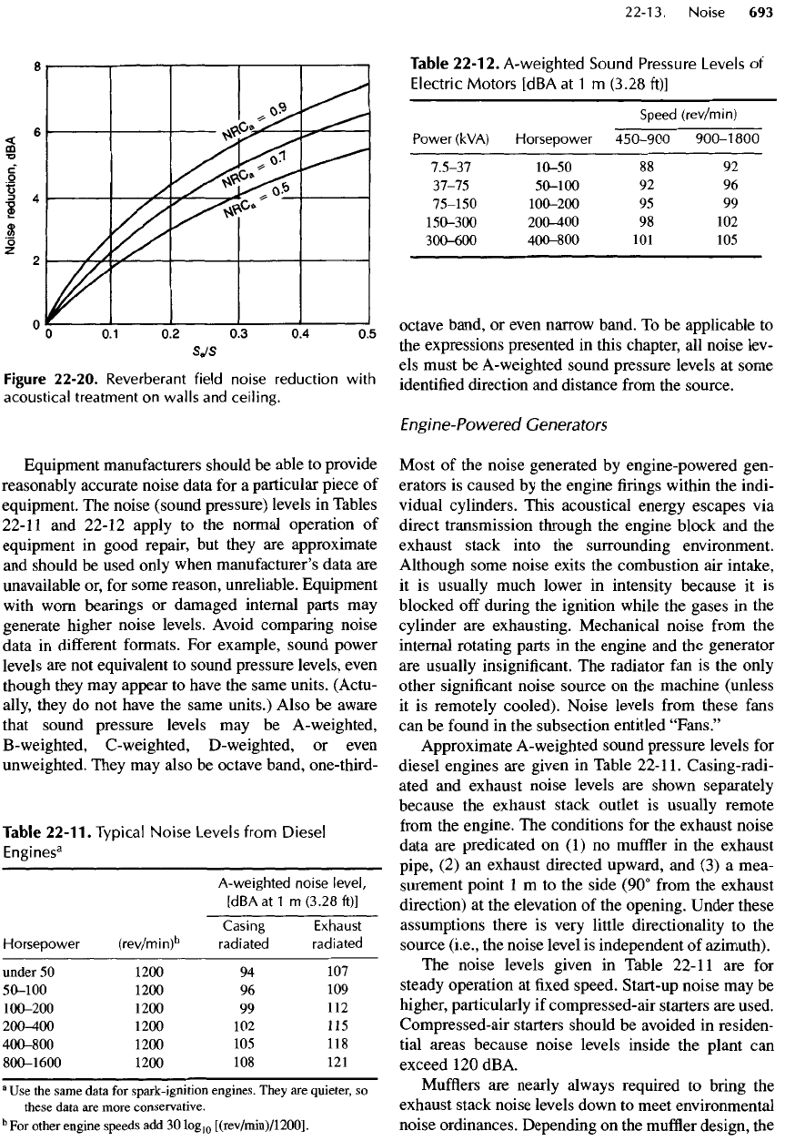
Figure
22-20.
Reverberant
field
noise
reduction
with
acoustical
treatment
on
walls
and
ceiling.
Equipment
manufacturers
should
be
able
to
provide
reasonably accurate noise data
for a
particular
piece
of
equipment.
The
noise (sound pressure) levels
in
Tables
22-11
and
22-12 apply
to the
normal operation
of
equipment
in
good repair,
but
they
are
approximate
and
should
be
used only when manufacturer's data
are
unavailable
or, for
some reason, unreliable. Equipment
with
worn bearings
or
damaged internal parts
may
generate higher noise levels.
Avoid
comparing noise
data
in
different
formats.
For
example,
sound power
levels
are not
equivalent
to
sound pressure levels, even
though
they
may
appear
to
have
the
same units. (Actu-
ally,
they
do not
have
the
same units.) Also
be
aware
that
sound pressure levels
may be
A-weighted,
B
-weighted,
C-
weighted,
D-
weighted,
or
even
unweighted. They
may
also
be
octave band, one-third-
Table
22-11.
Typical
Noise
Levels
from
Diesel
Engines
3
A-weighted
noise
level,
[dBAatl
m
(3.28
ft)]
Casing
Exhaust
Horsepower
(rev/mi
n)
b
radiated
radiated
under
50
1200
94 107
50-100
1200
96 109
100-200
1200
99 112
200-400
1200
102 115
400-800
1200
105
118
800-1600
1200
108 121
a
Use the
same
data
for
spark-ignition engines. They
are
quieter,
so
these
data
are
more conservative.
b
For
other engine speeds
add 30
Iog
10
[(rev/min)/1200].
Table
22-12.
A-weighted
Sound
Pressure
Levels
of
Electric
Motors
[dBA
at 1 m
(3.28
ft)]
Speed
(rev/min)
Power
(kVA)
Horsepower
450-900
900-1
800
7.5-37
10-50
88 92
37-75
50-100
92 96
75-150
100-200
95 99
150-300
200-400
98 102
300-600
400-800
101 105
octave band,
or
even narrow band.
To be
applicable
to
the
expressions presented
in
this chapter,
all
noise lev-
els
must
be
A-weighted sound pressure levels
at
some
identified
direction
and
distance
from
the
source.
Engine-Powered Generators
Most
of the
noise generated
by
engine-powered gen-
erators
is
caused
by the
engine
firings
within
the
indi-
vidual
cylinders. This acoustical energy escapes
via
direct transmission through
the
engine block
and the
exhaust
stack into
the
surrounding environment.
Although
some noise exits
the
combustion
air
intake,
it
is
usually much lower
in
intensity because
it is
blocked
off
during
the
ignition while
the
gases
in the
cylinder
are
exhausting. Mechanical noise
from
the
internal rotating parts
in the
engine
and the
generator
are
usually insignificant.
The
radiator
fan is the
only
other
significant
noise source
on the
machine (unless
it
is
remotely
cooled).
Noise levels
from
these
fans
can
be
found
in the
subsection entitled
"Fans."
Approximate A-weighted sound pressure levels
for
diesel
engines
are
given
in
Table
22-11.
Casing-radi-
ated
and
exhaust noise levels
are
shown separately
because
the
exhaust stack outlet
is
usually remote
from
the
engine.
The
conditions
for the
exhaust
noise
data
are
predicated
on (1) no
muffler
in the
exhaust
pipe,
(2) an
exhaust directed upward,
and (3) a
mea-
surement
point
1 m to the
side (90°
from
the
exhaust
direction)
at the
elevation
of the
opening. Under these
assumptions there
is
very little directionality
to the
source
(i.e.,
the
noise level
is
independent
of
azimuth).
The
noise levels given
in
Table
22-11
are for
steady operation
at fixed
speed.
Start-up
noise
may be
higher, particularly
if
compressed-air starters
are
used.
Compressed-air starters should
be
avoided
in
residen-
tial areas because noise levels inside
the
plant
can
exceed
120
dBA.
Mufflers
are
nearly always required
to
bring
the
exhaust
stack noise levels down
to
meet environmental
noise ordinances. Depending
on the
muffler
design,
the
engine,
and the
operating speed,
mufflers
usually
reduce
noise
by 10 to 40
dBA. Most manufacturers
provide exhaust noise data
for
their engines, with
a
variety
of
mufflers,
matched
to the
engine operating
at
fixed-governed
speeds.
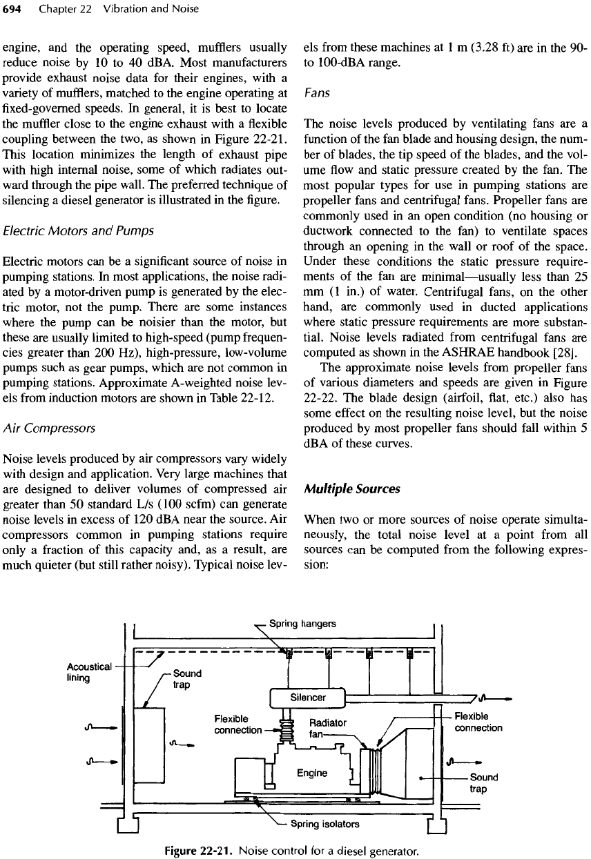
In
general,
it is
best
to
locate
the
muffler
close
to the
engine exhaust with
a flexible
coupling between
the
two,
as
shown
in
Figure
22-21.
This location minimizes
the
length
of
exhaust pipe
with
high internal noise, some
of
which radiates out-
ward
through
the
pipe wall.
The
preferred technique
of
silencing
a
diesel generator
is
illustrated
in the figure.
Electric
Motors
and
Pumps
Electric motors
can be a
significant
source
of
noise
in
pumping
stations.
In
most applications,
the
noise radi-
ated
by a
motor-driven pump
is
generated
by the
elec-
tric motor,
not the
pump. There
are
some instances
where
the
pump
can be
noisier than
the
motor,
but
these
are
usually limited
to
high-speed (pump frequen-
cies greater than
200
Hz), high-pressure, low-volume
pumps such
as
gear pumps, which
are not
common
in
pumping
stations. Approximate
A-
weighted
noise lev-
els
from
induction motors
are
shown
in
Table
22-12.
Air
Compressors
Noise levels produced
by air
compressors vary widely
with
design
and
application.
Very
large machines that
are
designed
to
deliver volumes
of
compressed
air
greater than
50
standard
L/s
(100
scfm)
can
generate
noise levels
in
excess
of
120
dBA
near
the
source.
Air
compressors common
in
pumping stations require
only
a
fraction
of
this capacity and,
as a
result,
are
much
quieter (but still rather noisy). Typical noise lev-
els
from
these
machines
at 1 m
(3.28
ft) are in the 90-
to
100-dBA
range.
Fans
The
noise levels produced
by
ventilating
fans
are a
function
of the fan
blade
and
housing design,
the
num-
ber of
blades,
the tip
speed
of the
blades,
and the
vol-
ume
flow and
static pressure created
by the
fan.
The
most
popular types
for use in
pumping stations
are
propeller
fans
and
centrifugal
fans.
Propeller
fans
are
commonly
used
in an
open condition
(no
housing
or
ductwork
connected
to the
fan)
to
ventilate spaces
through
an
opening
in the
wall
or
roof
of the
space.
Under
these conditions
the
static pressure require-
ments
of the fan are
minimal
—
usually
less than
25
mm (1
in.)
of
water. Centrifugal
fans,
on the
other
hand,
are
commonly used
in
ducted applications
where static pressure requirements
are
more substan-
tial. Noise levels radiated
from
centrifugal
fans
are
computed
as
shown
in the
ASHRAE handbook
[28].
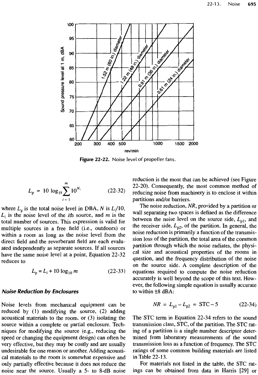
The
approximate
noise
levels
from
propeller
fans
of
various diameters
and
speeds
are
given
in
Figure
22-22.
The
blade design (airfoil,
flat,
etc.) also
has
some
effect
on the
resulting noise level,
but the
noise
produced
by
most
propeller
fans
should
fall
within
5
dBA
of
these curves.
Multiple
Sources
When
two or
more sources
of
noise operate simulta-
neously,
the
total noise level
at a
point
from
all
sources
can be
computed
from
the
following expres-
sion:
Figure
22-21.
Noise
control
for a
diesel
generator.
m
Lp=
10
1Og
10
^
10
W
'
(22-32)
I=
1
where
L
p
is the
total noise level
in
DBA,
N is
L
1
/!
O,
L
1
is the
noise level
of the
/th
source,
and m is the
total
number
of
sources. This expression
is
valid
for
multiple
sources
in a
free
field
(i.e.,
outdoors)
or
within
a
room
as
long
as the
noise level
from
the
direct
field and the
reverberant
field are
each evalu-
ated independently
as
separate sources.
If all
sources
have
the
same noise level
at a
point, Equation 22-32
reduces
to
Lp
=
L
1
-H-IOlOg
10
Ui
(22-33)
Noise
Reduction
by
Enclosures
Noise levels
from
mechanical equipment
can be
reduced
by (1)
modifying
the
source,
(2)
adding
acoustical
materials
to the
room,
or (3)
isolating
the
source
within
a
complete
or
partial enclosure. Tech-
niques
for
modifying
the
source (e.g., reducing
the
speed
or
changing
the
equipment design)
can
often
be
very
effective,
but
they
may be
costly
and are
usually
undesirable
for one
reason
or
another. Adding acousti-
cal
materials
to the
room
is
somewhat expensive
and
only
partially
effective
because
it
does
not
reduce
the
noise near
the
source. Usually
a 5- to
8-dB
noise
reduction
is the
most that
can be
achieved
(see
Figure
22-20). Consequently,
the
most common method
of
reducing noise
from
machinery
is to
enclose
it
within
partitions and/or
barriers.
The
noise reduction,
NR,
provided
by a
partition
or
wall separating
two
spaces
is
defined
as the
difference
between
the
noise level
on the
source side,
L
pl
,
and
the
receiver side,
L
p2
,
of the
partition.
In
general,
the
noise reduction
is
primarily
a
function
of the
transmis-
sion loss
of the
partition,
the
total area
of the
common
partition
through which
the
noise
radiates,
the
physi-
cal
size
and
acoustical
properties
of the
rooms
in
question,
and the
frequency distribution
of the
noise
on
the
source
side.
A
complete
description
of the
equations required
to
compute
the
noise
reduction
accurately
is
well beyond
the
scope
of
this text. How-
ever,
the
following simple equation
is
usually accurate
to
within
±8
dBA:
NR
=
L
pl
-L
p2
=
STC
-5
(22-34)
The STC
term
in
Equation 22-34 refers
to the
sound
transmission class, STC,
of the
partition.
The STC
rat-
ing
of a
partition
is a
single number descriptor deter-
mined
from
laboratory measurements
of the
sound
transmission loss
as a
function
of
frequency.
The STC
ratings
of
some common building materials
are
listed
in
Table
22-
13.
For
materials
not
listed
in the
table,
the STC
rat-
ings
can be
obtained
from
data
in
Harris
[29]
or
Figure
22-22. Noise level
of
propeller
fans.
Table
22-13.
Approximate
STC
Ratings
for
Common
Building
Materials
Material
STC
a
Poured
concrete,
150-300
mm
(6-12
in.) thick
50
Hollow
concrete block,
200 mm (8
in.) thick, unpainted
40
Steel
acoustical panel,
100 mm (4
in.)
thick
40
Dry
wall
partition,
5
150 mm (6
in.) thick
35
Dry
wall
partition,
0
150 mm (6
in.) thick
40
Safety
glass, 6.35
mm
(V
4
in.) thick
30
Hollow
metal door,
without
seals
20
Metal
louver, more
than
50%
open area
2
a
Note
that
the STC
values
are not
additive
for
composites:
two
partitions
each
with
an STC of 35 do not
yield
an STC of 70.
Each
composite
must
be
separately
tested.
b
Metal
studs
with
1
layer
of
gypsum
board
on
each
side.
c
Batt
insulation
between
metal
studs
and
gypsum
board
on
each
side.
approximated
from
the
surface weight
of
solid materi-
als
using
the
following formula:
STC = 8 + 17
Iog
10
w
(22-35a)
where
w
is the
surface mass
of the
material
in
kilo-
grams
per
square meter.
In
U.S. customary units,
the
expression
is
STC
=
20+17
Iog
10
w
(22-35b)
where
w is the
surface weight
in
pounds mass
per
square
foot.
In
most applications,
an
enclosure
is
made
from
more than
one
material.
For
example,
the
door
and
roof
are
usually constructed
differently
from
the
walls,
and
there
may be
openings
for
ventilation.
To
evaluate
this complex situation, calculate
the
compos-
ite
sound transmission class,
STC
C
.
The
composite
STC can be
determined
from
substituting
the
exposed
areas
and STC of
each component
of the
barrier
sys-
tem
into
the
expression
-i
STC
C
=
-IGlOg
10
!//£
A
1
-IO""'
(22-36)
/
=
i
-I
where
W
is
STQ/10,
A
1
and STQ are the
exposed sur-
face
area
and STC
rating
of the
/th
material,
and s is
the
total exposed surface area
of all
components
in the
direction
of the
listener.
In
most situations,
the
isola-
tion
provided
by a
composite system
is
only
as
good
as
its
weakest component, unless that component
has a
surface
area less than one-tenth
of the
other compo-
nents.
A
unique
but
common example
is the
enclosure
with
an
opening because openings have
an STC of O.
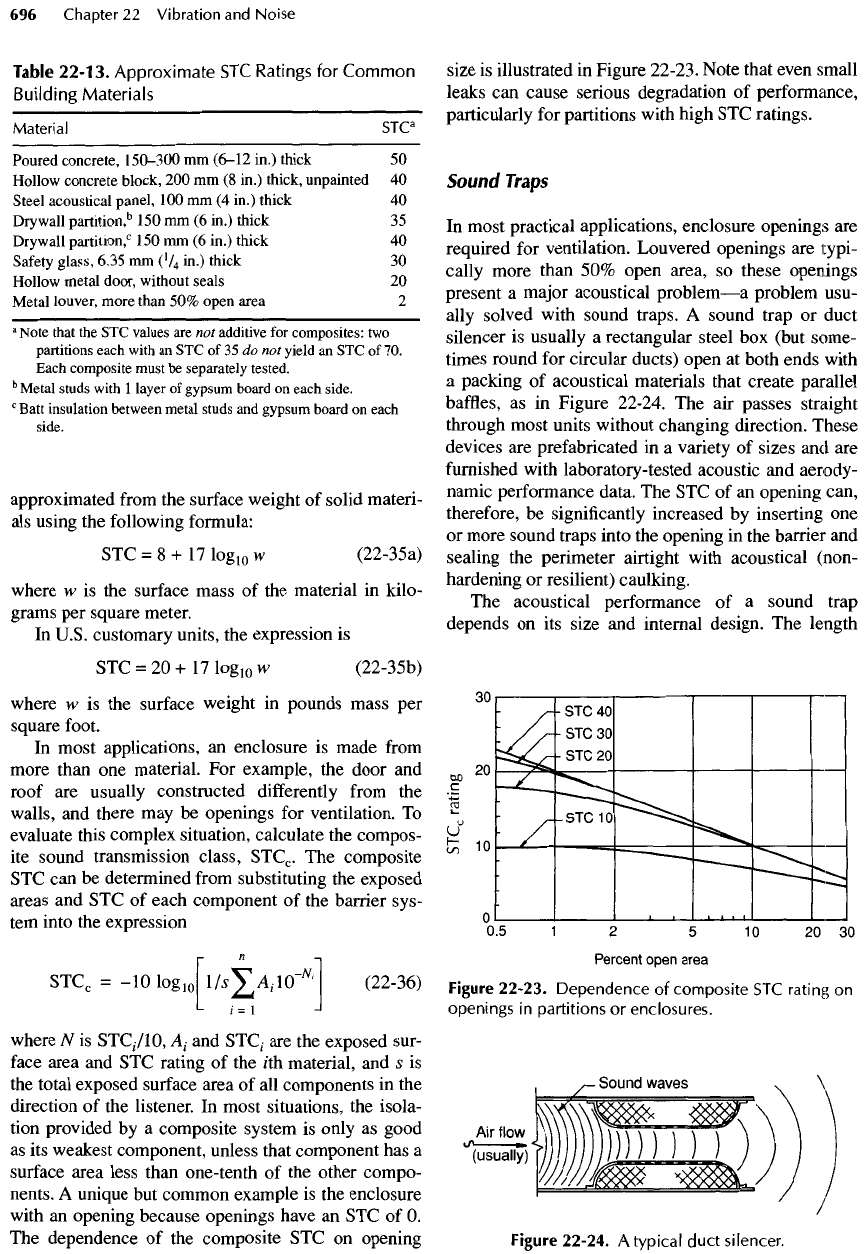
The
dependence
of the
composite
STC on
opening
size
is
illustrated
in
Figure
22-23.
Note that even small
leaks
can
cause serious degradation
of
performance,
particularly
for
partitions with high
STC
ratings.
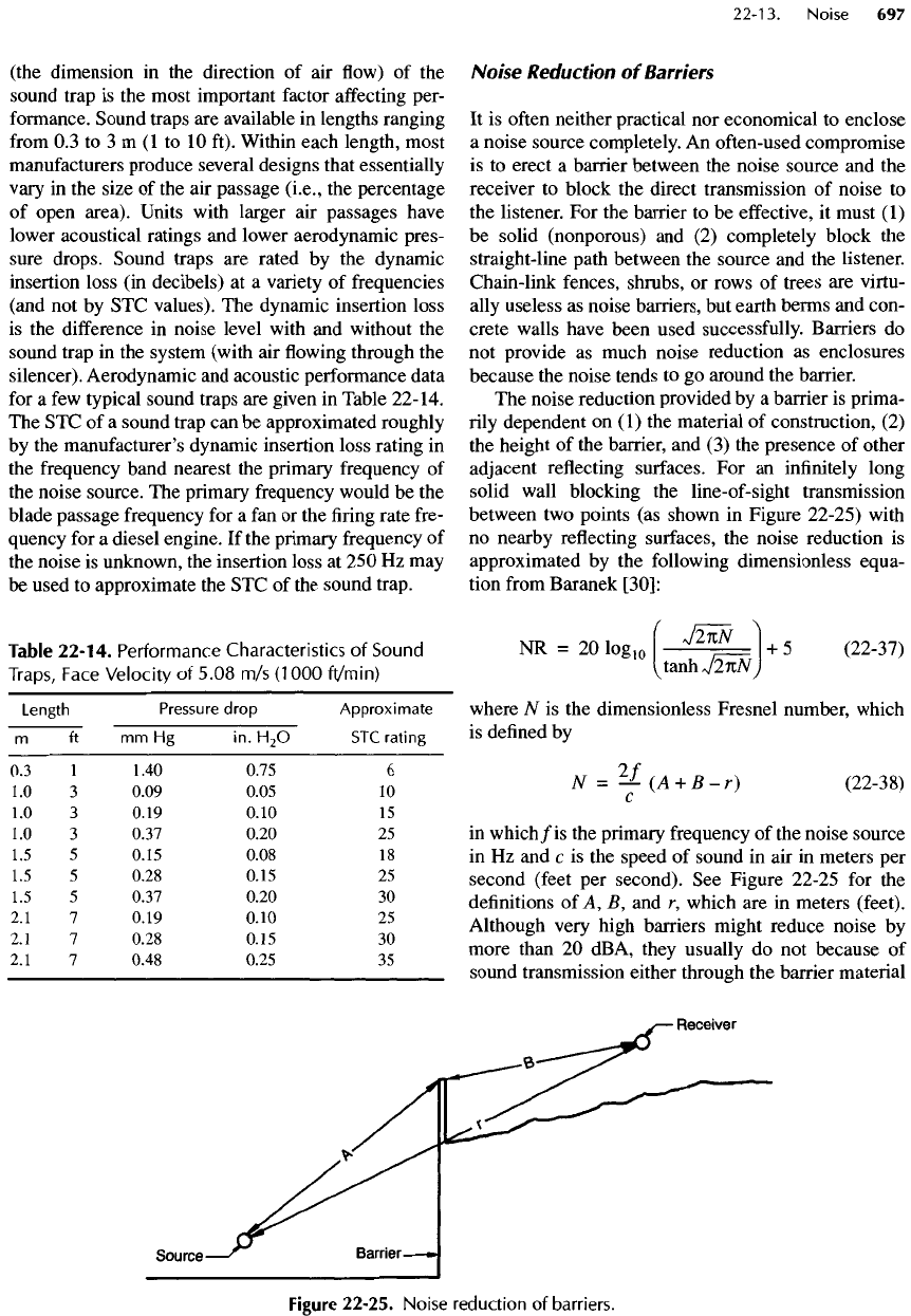
Sound
Traps
In
most practical applications, enclosure openings
are
required
for
ventilation. Louvered openings
are
typi-
cally more than
50%
open area,
so
these
openings
present
a
major
acoustical
problem
—
a
problem
usu-
ally
solved with sound traps.
A
sound trap
or
duct
silencer
is
usually
a
rectangular steel
box
(but some-
times round
for
circular ducts) open
at
both ends with
a
packing
of
acoustical materials that create parallel
baffles,
as in
Figure 22-24.
The air
passes straight
through
most units without changing direction. These
devices
are
prefabricated
in a
variety
of
sizes
and are
furnished
with laboratory-tested acoustic
and
aerody-
namic performance data.
The STC of an
opening can,
therefore,
be
significantly increased
by
inserting
one
or
more sound traps into
the
opening
in the
barrier
and
sealing
the
perimeter airtight with acoustical (non-
hardening
or
resilient) caulking.
The
acoustical performance
of a
sound trap
depends
on its
size
and
internal design.
The
length
Figure
22-23.
Dependence
of
composite
STC
rating
on
openings
in
partitions
or
enclosures.
Figure
22-24.
Atypical
duct
silencer.
(the
dimension
in the
direction
of air flow) of the
sound
trap
is the
most important
factor
affecting
per-
formance.
Sound traps
are
available
in
lengths ranging
from
0.3 to 3 m (1 to 10
ft). Within each length, most
manufacturers
produce several designs that essentially
vary
in the
size
of the air
passage
(i.e.,
the
percentage
of
open area). Units with larger
air
passages have
lower
acoustical ratings
and
lower aerodynamic pres-
sure drops. Sound traps
are
rated
by the
dynamic
insertion loss
(in
decibels)
at a
variety
of
frequencies
(and
not by STC
values).
The
dynamic
insertion
loss
is
the
difference
in
noise level with
and
without
the
sound
trap
in the
system (with
air flowing
through
the
silencer). Aerodynamic
and
acoustic performance data
for
a few
typical sound traps
are
given
in
Table
22-14.
The STC of a
sound trap
can be
approximated roughly
by
the
manufacturer's dynamic insertion loss rating
in
the
frequency
band nearest
the
primary frequency
of
the
noise source.
The
primary frequency would
be the
blade passage frequency
for a fan or the firing
rate fre-
quency
for a
diesel engine.
If the
primary frequency
of
the
noise
is
unknown,
the
insertion loss
at 250 Hz may
be
used
to
approximate
the STC of the
sound trap.
Table
22-14.
Performance
Characteristics
of
Sound
Traps,
Face
Velocity
of
5.08
m/s
(1000
ft/min)
Length
Pressure
drop
Approximate
m ft mm Hg in.
H
2
O
STC
rating
0.3
1
1.40 0.75
6
1.0
3
0.09 0.05
10
1.0 3
0.19 0.10
15
1.0
3
0.37 0.20
25
1.5
5
0.15 0.08
18
1.5
5
0.28 0.15
25
1.5
5
0.37 0.20
30
2.1
7
0.19 0.10
25
2.1
7
0.28 0.15
30
2.1
7
0.48 0.25
35
Noise
Reduction
of
Barriers
It
is
often
neither
practical
nor
economical
to
enclose
a
noise source completely.
An
often-used compromise
is
to
erect
a
barrier between
the
noise source
and the
receiver
to
block
the
direct transmission
of
noise
to
the
listener.
For the
barrier
to be
effective,
it
must
(1)
be
solid (nonporous)
and (2)
completely block
the
straight-line path between
the
source
and the
listener.
Chain-link fences, shrubs,
or
rows
of
trees
are
virtu-
ally
useless
as
noise
barriers,
but
earth
berms
and
con-
crete walls have been used successfully. Barriers
do
not
provide
as
much
noise
reduction
as
enclosures
because
the
noise tends
to go
around
the
barrier.
The
noise reduction provided
by a
barrier
is
prima-
rily dependent
on (1) the
material
of
construction,
(2)
the
height
of the
barrier,
and (3) the
presence
of
other
adjacent
reflecting surfaces.
For an
infinitely
long
solid wall blocking
the
line-of-sight
transmission
between
two
points
(as
shown
in
Figure 22-25) with
no
nearby reflecting surfaces,
the
noise reduction
is
approximated
by the
following dimensionless equa-
tion
from
Baranek
[3O]:
NR
- 20
lo
glo
J
2n
N
+
5
(22-37)
I^
tanhV2
nNj
where
Af
is the
dimensionless Fresnel number, which
is
defined
by
N
=
7
^-
(A +
B-r)
(22-38)
in
which/
is
the
primary
frequency
of the
noise source
in
Hz and c is the
speed
of
sound
in air in
meters
per
second
(feet
per
second).
See
Figure 22-25
for the
definitions
of A,
B,
and r,
which
are in
meters (feet).
Although very high barriers might reduce noise
by
more than
20
dBA, they usually
do not
because
of
sound
transmission either through
the
barrier material
Figure
22-25.
Noise
reduction
of
barriers.