Pumping Station Desing - Second Edition by Robert L. Sanks, George Tchobahoglous, Garr M. Jones
Подождите немного. Документ загружается.

against which both
the
supply
and
exhaust
fans
must
operate. When used
in air
conditioning systems, such
energy-recovery devices
can
also precool
the hot
makeup
air by
thermal exchange with cooler exhaust
air. This dual
use
makes them more economical
in
applications requiring heating
in
cold weather
and
refrigerated
air
conditioning
in
summer.
23-6. Corrosion Protection
Metallic equipment, especially ductwork,
is
suscepti-
ble to
deterioration
in
varying degrees
due to
mois-
ture,
acid
(from
hydrogen
sulfide
and
moisture),
and
salt
often
contained
in the air in wet
wells.
Raw
edges
of cut
metal sheets
and
surface
scratches pro-
vide
a
starting point
for
oxidation
to
spread under
coatings
of
metals such
as the
zinc
on
galvanized
steel. Type
316
stainless steel
is
generally corrosion
resistant,
but its
discoloration
may be
unacceptable
aesthetically. Copper
and
copper-bearing
materials
are
highly susceptible
to
attack
by
hydrogen
sulfide
and
should
be
avoided
or
protected
in
wastewater sta-
tions.
Aluminum
should
not be
used
in
damp chlorine
rooms. Where metals
are the
logical choice
for
items
such
as
louvers, dampers,
and
grilles, they should
be
type
316
stainless steel, aluminum,
or
galvanized
steel,
or be
protected with
an
epoxy
or
baked phe-
nolic corrosion-resistant coating applied
by the
man-
ufacturer.
Polyvinyl
chloride (PVC)
or fiberglass-reinforced
plastic (FRP)
are
more corrosion resistant (and more
expensive) than type
316
stainless steel,
but
their
detracting
characteristics
—
such
as fire and
smoke rat-
ings, structural strength, greater weight
and
support
requirements,
and the
greater
difficulty
of
on-site
modification
—
must
be
given
due
consideration.
PVC
and
FRP
ductwork
are
usually factory-fabricated
from
sheets
of
material
4.8 mm
(3/16 in.)
or
more
in
thick-
ness. Joints
in
either type
of
duct
can be
made
by
sol-
vent
welding.
FRP
joints also
can be
formed with
multiple
layers
of
glass cloth laid
up by
hand
in a
resin
binder. Duct accessories used, such
as
dampers, turn-
ing
vanes, hangers,
and
fasteners, should
be
equally
corrosion resistant.
Fans,
tanks,
and
piping
may
also
be
fabricated
from
PVC and
FRP. Heat exchangers (which must
be
metal
for
good heat
transfer)
should
be
protected
by
corro-
sion-resistant coatings, such
as
thermosetting
phenolics.
The
metal
is
dipped
and
then oven baked
for
several
hours.
Two or
more coats
may be
used
for
severe appli-
cations. Epoxy compounds
and
some phenolics
can be
applied cold
by
painting
or
spraying.
The
resistance
of
the
coatings
to the
various causes
of
corrosion
can be
obtained
from
their manufacturers.
The
heat-transfer
capability
of
corrosion-protected heat exchangers
may
be
decreased
by 15% or
more,
so
compare cost, energy,
and
permanence
in
making
a
selection.
The
types
and
severity
of
corrosion
to be
expected
should
be
ascertained
from
previous installations
at
the
same
or at a
similar
site,
if
possible.
Also consult
experienced coating vendors.
The
difficulty
and
cost
of
replacing unprotected components should
be
weighed against
the
cost
for
protection.
Note that cor-
rosion protection increases
first
cost
from
20 to
400%
but
replacement costs
can be
even higher.
Electrical switches
and
control components should
also
be
protected
from
corrosion. Such protection
can
be
provided
in a
number
of
different
ways.
•
Control hydrogen
sulfide
at the
source
to the
great-
est
extent
possible.
A
complete odor-control system
mitigates
the
problem except
for
electrical equip-
ment
within
wet
wells
or
under tank covers.
•
Isolate control equipment
in a
separate room
and
design
the
ventilation
to
exclude
sulfides
or, if
that
is
impossible, treat
the air
supply
for the
entire
room.
If
electronic equipment
is
installed, pressur-
ize the
room slightly
and
eliminate chlorine
and
other corrosive gases
as
well.
•
Hermetically seal relays
and
switches
in
plastic
boxes attached
to
plastic conduit, seal
the
boxes
as
completely
as
possible,
and put
potassium perman-
ganate pellets
in the
bottom
of the
boxes.
•
Pressurize
the
boxes
or
panels
to
maintain
25
kPa
(0.1
in. WC)
with either uncontaminated
air or
with
air filtered
through potassium permanganate
and
activated carbon. Such pressurizing
in
accordance
with
NEC 500
also reduces enclosure explosion
hazard
ratings
from
NEC
Class
1,
Division
1 to
Class
1,
Division
2.
Adequate
differential
pressure
can
be
monitored
by an
attached pressure switch
and
alarm.
To
guard against excessive compressed
air
consumption
if the
bolts
are
loose,
the
gaskets
are
old,
or the
panel
is
warped,
a
limited amount
of
air can be
supplied
by a
small, inexpensive, dia-
phragm-type
fish
tank
air
pump.
23-7. Sequence
of
Design Steps
Pumping station design
is a
cooperative
effort
among
the
various design disciplines that must
be
coordi-
nated
as the
design progresses. Each design step
affecting
other disciplines should have
confirmed
agreement before proceeding
to
avoid later redesign.
Step
1
:
Write
and
distribute
a
design memorandum
defining
the
applicable codes,
the
indoor
and
out-
door design temperatures,
the
building materials
and
orientation,
the
sources
and
amounts
of
heat
gain
(especially
from
motors
and
engines),
and the
design
air
change rate
for
each
space.
State
the
energy source
to be
used
and
describe
the
proposed
ventilating,
heating,
and
cooling systems.
Step
2:
Calculate
the
heating
and
cooling loads
for
each space. Measure
and
record wall, glass,
and
roof
areas
from
the
architectural
plans.
List
expo-
sure
directions
and
calculate space volumes. Obtain
or
calculate heat transmission
coefficients
(U
val-
ues)
for
wall, roof,
and
window construction.
Use
the
methods
in the
ASHRAE
Handbook
of
Funda-
mentals
[12]
to
calculate
the
heat loss
and the
heat
gain
for
each space.
Sum the
heating
or
cooling
loads
in
watts (British thermal units
per
hour)
for
each
air
handling
unit
and
obtain
the
grand totals.
Step
3:
From
the
appropriate designer, obtain
the
locations
of the
main pumps
and
piping, cranes
or
hoists, columns, stairs, beams,
and
other obstacles
to
air
distribution. Also obtain
the
heat emissions
from
simultaneously operating equipment. Calcu-
late
the
initial ventilation rates starting with
12 air
changes
per
hour
for wet
wells (more
in
some states
or
for
severe conditions)
and 6 (or
more)
air
changes
per
hour
for dry
wells. Make preliminary
equipment selections. Estimate
the
outside
air
infil-
tration
to
each space
by
either
the
crack
or the air
change method,
and
calculate
the
expected outdoor
air
heating
and
cooling loads.
See the
ASHRAE
Handbook
of
Fundamentals [12]
for
details
of the
crack
and air
change methods.
Step
4:
From space volumes, heat gains,
and
design
air
change rates, calculate
the
normal
and
required
purge
air
supply quantities
for
each space.
If the
summer
airflow
for
heat removal exceeds
30 air
changes
per
hour, consider evaporative
or
refriger-
ated cooling. Choose supply
and
return/exhaust reg-
ister locations, assign
the
proper
air
quantity
to
each, and,
from
catalog data, select register sizes
to
give
desired
air
throw (for supply)
or
velocity
(return/exhaust).
Note
the
corresponding pressure
drops.
Step
5:
Make
an
initial estimate
of
HVAC
motor num-
ber and
sizes
for the
electrical engineer.
Fan
motor
horsepower
can be
approximated
in SI
units
by
W=^
(23-2a)
where
W is
brake watts,
Q is the
airflow
in
cubic
meters
per
second,
R is the
static resistance
in
pas-
cals,
and E is the fan
static
efficiency
as a
decimal.
In
U.S.
customary units,
bhp
=
6?5lE
(23
-
2b)
where
bhp is
brake horsepower,
Q is the
airflow
in
cubic
feet
per
minute,
R is the
static resistance
in
inches
of
water column,
and E is the fan
static
effi-
ciency
as a
decimal.
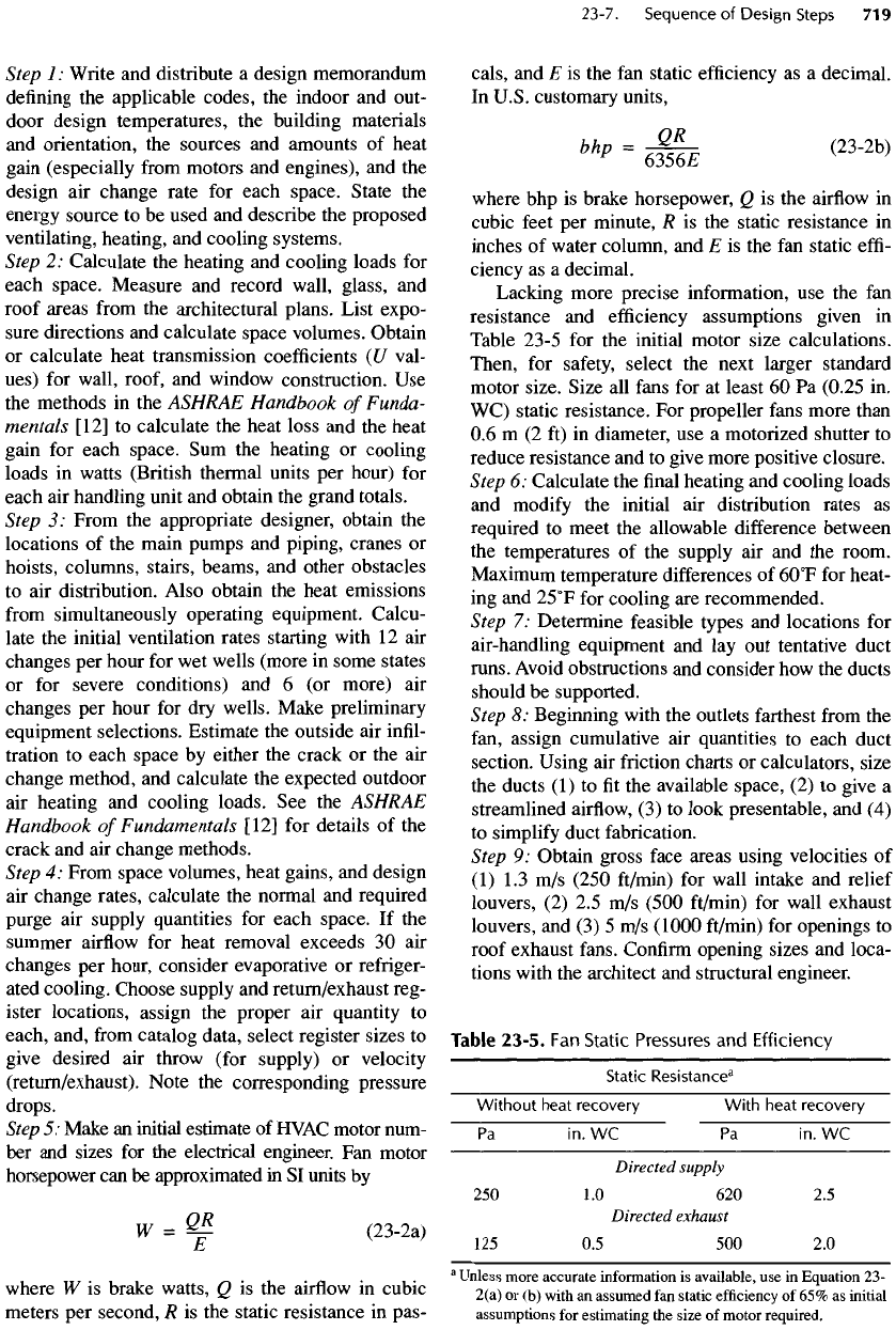
Lacking more precise information,
use the fan
resistance
and
efficiency
assumptions given
in
Table 23-5
for the
initial
motor size calculations.
Then,
for
safety,
select
the
next larger standard
motor size. Size
all
fans
for at
least
60 Pa
(0.25
in.
WC)
static resistance.
For
propeller
fans
more than
0.6 m (2 ft) in
diameter,
use a
motorized shutter
to
reduce resistance
and to
give more positive closure.
Step
6:
Calculate
the final
heating
and
cooling loads
and
modify
the
initial
air
distribution rates
as
required
to
meet
the
allowable
difference
between
the
temperatures
of the
supply
air and the
room.
Maximum
temperature
differences
of
6O
0
F
for
heat-
ing
and
25
0
F
for
cooling
are
recommended.
Step
7:
Determine feasible types
and
locations
for
air-handling equipment
and lay out
tentative duct
runs.
Avoid
obstructions
and
consider
how the
ducts
should
be
supported.
Step
8:
Beginning with
the
outlets
farthest
from
the
fan,
assign cumulative
air
quantities
to
each duct
section. Using
air
friction
charts
or
calculators, size
the
ducts
(1) to fit the
available space,
(2) to
give
a
streamlined
airflow,
(3) to
look presentable,
and (4)
to
simplify
duct fabrication.
Step
9:
Obtain gross
face
areas using
velocities
of
(1)
1.3 m/s
(250
ft/min)
for
wall intake
and
relief
louvers,
(2) 2.5 m/s
(500
ft/min)
for
wall exhaust
louvers,
and (3) 5 m/s
(1000
ft/min)
for
openings
to
roof exhaust
fans.
Confirm
opening
sizes
and
loca-
tions with
the
architect
and
structural engineer.
Table
23-5.
Fan
Static
Pressures
and
Efficiency
Static
Resistance
3
Without
heat
recovery
With
heat
recovery
Pa in. WC Pa in. WC
Directed
supply
250 1.0 620 2.5
Directed
exhaust
125
0.5 500 2.0
a
Unless
more
accurate
information
is
available,
use in
Equation
23-
2(a)
or (b)
with
an
assumed
fan
static
efficiency
of 65% as
initial
assumptions
for
estimating
the
size
of
motor
required.
Step
10:
Draw
the
duct systems
on the
plan. From
the
resistances
for
registers, straight lengths
of
ducts,
and
fittings,
cumulatively
sum the
actual friction drop
of
the
longest duct
run
from
the
farthest
point back
to
the
fan. Duct
friction
can be
calculated
by the
Darcy-
Weisbach
equation, which
for air
takes
the
form
p
=
f
D
(cfxL/D)p
v
(23-3)
where
p is the
total pressure
friction
loss
in
pascals
(inches
of
water column),
/
D
is the
friction
factor
(dimensionless),
c/is
the
conversion
factor,
L is the
duct
length
in
meters (inches),
D is the
duct diame-
ter
in
meters (inches),
and
p
v
is the
velocity pres-
sure
in
pascals (inches
of
water column).
The
friction
factor
is a
function
of
Reynolds number,
however,
and can be
calculated only
by
iteration.
Air
resistance
for
straight ducts
is
more easily cal-
culated
with
a
slide rule made
especially
for
this
purpose,
with
a
programmable calculator,
or
with
a
computer. Duct
friction
tables
and
charts
and a
list-
ing of fitting
friction
losses
are
available
in the
ASHRAE
Handbook
of
Fundamentals
[12].
Step
11
:
Make
final
best selections
of the
heat trans-
fer
and
air-handling equipment based
on the
design
flowrate
and
the
calculated total
air
resistance,
including
the
friction
drops
for
louvers, dampers,
filters,
coils,
ducts,
and
registers.
The
friction drop
for
clean, pleated glass
fiber filters is
about
25 Pa
(0.1
in.
WC),
but the fan
motor must
be
sized
to
supply
the
required
air at a
dirty
filter
resistance
of
120
to 160 Pa
(0.5
to
0.65
in.
WC).
Filter
and
coil
resistances
are
usually considered
to be
part
of the
external
resistance
—
separate
from
the
internal
resistance
of the
air-handling unit given
by the
unit
manufacturer.
Step
12:
Show
the
selected
air
supply
and
exhaust
equipment
on the
plans. Provide
(1)
raised house-
keeping pads
for floor-mounted
units,
(2)
vibration-
isolated supports
for
suspended
and
wall-mounted
units,
(3) flexible
connectors
for
duct connections,
and
(4)
ample access
for filter,
motor, belt,
and
bearing maintenance. Allow space
for
replacing
heating
and
cooling coils
and filters.
Provide direct access
to the
equipment. Floor-
mounted
units are, therefore, preferable
to
ceiling-
hung
equipment. Rooftop equipment
is
more likely
to be
maintained
if it is
accessible
by
stairs.
Step
13:
Select
the
additional air-handling equip-
ment
for
purging
and
summer heat removal.
The
equipment
required
may be
only strategically
placed high wall
or
roof exhaust
fans
and low
dam-
pered weatherproof wall intakes. Nonducted intakes
and
exhaust
fans
should
be
selected
to
result
in no
more than
60 Pa
(0.25
in. WC)
negative pressure
within
the
space.
A
force
of
about
120 N (27
Ib)
is
required
to
open
a
standard outwardly swinging
door against such
a
vacuum.
Step
14:
Recheck
the
actual motor kilowatts
(or
horsepower) needed
for the
designed systems
and
correct
the
motor list
as
required. Make sure motors
are
selected
for the
electrical
characteristics avail-
able. Coordinate motor, starter,
and
control loca-
tions with
the
electrical engineer
so
that
all of the
necessary wiring
is
provided. Motors
and
controls
should
be
listed
by
Underwriters Laboratories
(UL).
High-efficiency
motors
are
cost
effective
for
continuously operating
fans
and
pumps.
A
specifi-
cation requirement that air-handling equipment
shall
be
rated
in
accordance with
the
AMCA
No. 99
Standards gives
increased
assurance that
it
will
meet
the
rated capacity.
Step
15:
Specify
each component
of the
system,
stating each important criterion
of
construction
and
performance
necessary
to
determine
the
acceptabil-
ity
of
items subsequently submitted
by the
success-
ful
bidder. Equipment schedules
are a
simple
way
of
summarizing required equipment designations,
capacities,
and
special
features. Write
a
perfor-
mance description
of (1) the
intended sequence
of
operation
and (2) the
operating temperatures.
Require
a
submittal
of
control components
and
schematic
and
wiring diagrams. Require
accep-
tance tests
to
ensure that
the
installed system
func-
tions
as
intended
and
meets specification
requirements.
23-8.
Ventilating
System
Design
Pump rooms located where
the
outdoor temperature
range
is
between
freezing
and
35
0
C
(95
0
F)
and in
areas where
noise
need
not be
suppressed
can
often
be
ventilated
without
ductwork. Those rooms located
below grade, however, require ductwork.
For
pump
rooms
at or
above grade, louvered
air
intakes (with
dampers
and filters) and
roof exhaust
fans
(with grav-
ity
shutters
and
sequencing thermostats)
are
sufficient.
For
lower outdoor temperatures, heating
is
usually
required.
For
higher temperatures, some
form
of
cool-
ing
is
normally necessary.
Heating
and
cooling calculations
are
always neces-
sary
to
determine
the
required extent
of
heat removal
or
heat addition.
The air
quantities
to be
handled,
as
derived
from
the
heat load calculations, must
be
com-
pared
to
those determined
by
required
air
change rates
or
other
criteria,
and the
larger quantity must
be
used
as
the
design basis.
Heating
Load
Calculations
Structure
heat load
is
composed
of (1)
transmission
loss through walls, windows,
and
roof
and (2)
infiltra-
tion
of
cold outside air, which must
be
heated
to the
design space temperature.
The
transmission loss through
any
portion
of the
structure
envelope
is
H
= U x A x
A7
(23-4)
where,
in SI
units,
H is the
heat loss
in
watts
per
hour,
U
is the
overall heat transmission coefficient
in W/
(m
2
• h •
0
C),
A is the
surface area
in
square meters,
and
AT
is the
inside-to-outside temperature difference
in
degrees Celsius.
In
U.S. customary units,
H is in
Brit-
ish
thermal units
per
hour,
U is in
Btu/(ft
2
• h •
0
F),
A is
in
square
feet,
and
A7
is in
degrees Fahrenheit. Trans-
mission
coefficients
for
typical walls, windows,
and
roofs
as
well
as
methods
of
calculating
the
coefficient
for
the
combinations
of
materials
are
given
in
Chapter
25 of the
ASHRAE Handbook
of
Fundamentals
[12].
Cooling
Calculations
Heat gain throughout
the
structure, which makes
up the
external cooling load,
is
more
difficult
to
calculate than
heat
loss because
of the
effects
of
radiated heat
from
the
sun.
This additional heat source must
be
considered
in
addition
to the
heat gain
by
conduction
due to the
differ-
ence between outdoor
and
indoor temperatures. Sunlight
does
not
heat space
air
directly,
but it
raises
the
tempera-
ture
of
sunlit
surfaces
as a
result
of
absorbed radiation.
Many
factors
influence
the
amount
and
timing
of
solar heat reaching
the
space.
The
intensity
of
incident
solar radiation depends
on
latitude, time
of
year, time
of
day, cloud cover,
and
atmospheric pollution.
The
time
lag
between solar heat input
and
interior
air
tem-
perature rise
may
vary
from
a few
minutes
to
several
hours.
The lag is
affected
by the
surface color
of the
exterior,
the
heat storage capacity
and the
insulating
value
of the
construction,
and the
daily outdoor tem-
perature
range, among other
factors.
The
combined heat
from
both
the
higher outdoor
temperature
and
solar radiation moves progressively
through
walls
and
roof,
finally
raising
the
interior sur-
face
temperatures. Loss
from
those surfaces occurs
by
radiation
to
cooler
surfaces
and by
convection
to the
adjacent
air.
Air
warmed
by
convection expands,
becomes lighter, rises,
and is
replaced
by
cooler
air,
which
continues
the
convective process.
Except
for
minor reflected losses, sunlight passes
directly
through clear glass
and is
absorbed
by the
interior
surfaces
it
strikes. Their increased tempera-
ture
transfers heat
to
other
cooler
surfaces
by
reradia-
tion
and to the air by
convection.
Simply stated, solar heat gain
is
taken into account
by
using
a
higher outdoor temperature than actually would
exist
at the
time considered
for
each heat gain calcula-
tion.
The
ASHRAE
Handbook
of
Fundamentals
[12]
contains tables
of
cooling load temperature
differential
(CLTD)
data (for
use in
calculating conduction heat gain
through
sunlit walls
and
roofs)
and
cooling load
factors
(CLF) (for calculating
the
solar radiation through glass).
Both
sets
of
data include
the
effect
of
time delay
due to
thermal storage.
The
total resistance
to
heat
transfer
for
each type
of
construction
is
found
by
adding
the
resis-
tances
of its
components,
as
illustrated
in
Example
23-1.
Peak
Heat
Gain
The
peak heat gain
to a
space
is the
largest
sum of
external
and
internal
heat gains that occur simulta-
neously.
Heat removal capacity,
in the
form
of
ventila-
tion
or
cooling, equal
to the
peak heat gain must
be
available
to
maintain
the
design space temperature.
External heat gain results
from
an
outdoor tempera-
ture that
is
higher than
the
indoor temperature
as
well
as
from
solar radiation. Internal heat gain comes pri-
marily
from
operating motors
and
engines.
Air
Intake
and
Exhaust
Openings
Intakes
for
ventilation
air
should
be
through
screened
louvers that exclude rain, snow, birds,
and
insects.
Ducted intakes that
are
connected
to
air-handling units
with
filters
that exclude insects need only bird screens.
Nonducted intakes should include insect screens
or
filters.
All
screens
and filters
must
be
readily
accessi-
ble for
cleaning
or
replacement. Bird screens
do not
need mesh openings smaller than
25 mm
(
1
I
2
in.).
The
air
resistance
of filters
used
at
unducted wall intakes
should
not
exceed
24 Pa
(0.1
in. WC)
when clean
to
limit negative pressure
in the
space
(created
by
exhaust
fans)
to 63 Pa
(0.25
in.
WC);
low
negative
pressure makes doors easier
to
open
and
close.
Both
the
louver
and
screen should
be
constructed
of a
cor-
rosion-resistant material
or
should have
a
corrosion-
protective coating. Provide
an
intake damper
at
each
louver
in
cold climates, preferably with positive clo-
sure
on
failure
of its
pneumatic
or
electric actuator.
Hurricane-prone locations
may
warrant
an
additional
manually
operated damper
(on the
outdoor
air
intake)
that
can be
locked closed when
a
storm approaches.
Air
exhaust openings should
be
protected
from
the
weather
by a
wall louver, hood, penthouse,
or
weather
cap.
The
discharge openings should
be
located
so as to
minimize
unwanted recirculation into
air
intakes.
A
high-velocity vertical discharge
of
untreated
wet
well
exhaust
air
—
about
20
m/s
(4000
ft/min),
which
requires
250 Pa (1 in. WC)
static
pressure
—
may
reduce odor near
the
station (but with attendant
noise).
A
thorough model study
of the
likely results (which
are not
readily predictable) should
precede
any use of
this approach
for
odor control.
Ducted
Ventilation
A
ducted
air
supply
is
usually necessary
to
achieve
the
desired
air
distribution pattern. Once delivered
to the
right
location,
the air can be
directed upward
or
down-
ward
by
registers (grilles with directional vanes
and
attached balancing dampers),
or it can be
more thor-
oughly
mixed with room
air by
diffusers
that give high
entrainment
of
room air.
The
distance
an
airstream
travels
after
leaving
the
outlet (the
"throw")
depends
on
its
velocity, temperature,
and any
obstructions
to
straight-line
flow.
Catalog data
on
grilles, registers,
and
diffusers
give
the
throw
and
pressure drop
for a
given
flowrate
of
standard air.
The
throw
is
longer
for an
out-
let
discharging horizontally within about
0.6 m (2 ft) of
a
smooth ceiling
due to the low
induction
of
room air.
Install
a
manual volume damper
in
each main duct
branch
and at
each inlet
or
outlet grille
to
allocate
or
"balance"
the
total
air
quantity among
the
various
points
of
supply
and
exhaust. Such dampers
are
fur-
nished
as a
standard part
of
registers,
but
must
be
sep-
arately
specified
for
grilles
and
diffusers.
Complete
testing
and
balancing
of
ducted systems should
be
specified
to
deliver
the
design
air
quantity within
10%
at
each register
and
diffuser.
Wherever
an air
duct penetrates
a
rated
fire
separa-
tion
required
by
code, install
an
accessible
fire
damper
of
equal
fire
rating. Codes generally require rated
fire
separations between
floors,
around vertical
shafts
and
stairs,
at the
envelope enclosing
life
safety
exitways,
and,
in
some instances, around mechanical equipment
rooms
and
storage rooms.
The fire
damper
is
held
open
by a
fusible
link that melts
and
allows
the fire
damper
to
close automatically
if the air
temperature
rises
above
its
fusion
point
52 or
74
0
C
(125
or
165
0
F).
The
fusible
link
is
selected
on the
basis
of
location
and
normal
air
temperature. Such dampers
are
required
by
NFPA Standard
9OA
(which
is
included
by
reference
in
many other codes)
to
prevent
fire and
smoke
from
spreading through
the air
ducts. High-
temperature thermostats
or
smoke detectors
(as
required
by
applicable codes) should
be
provided
and
interlocked
to
stop both
the
supply
and the
exhaust
fans
if fire is
detected. Some codes require tight-clos-
ing, remotely operable smoke dampers (which
are
actuated
by
smoke detectors)
at
certain locations.
Detailed duct design methods
are
given
in
Chapter
33 of the
ASHRAE
Handbook
of
Fundamentals
[12].
Ventilation
Controls
Excessive
and
intricate controls
for
ventilation sys-
tems
(or any
HVAC
system)
are
likely
to
result
in
more operational problems than they were intended
to
overcome.
The
rule
is to
keep controls
as
simple
as
feasible
while
still
maintaining
the
temperature within
an
appropriate range.
A
temperature variation
from
above
freezing
to
43
0
C
(UO
0
F)
would
not be
serious
in
an
unmanned pumping station,
but in an
occupied
office
or
control room
the
temperature variation
should
be
held
to a
range
of
6
0
C
(1O
0
F)
or
less.
The
following
are
suggested ventilation control
functions:
•
Energize controls when
the
supply
fan
starts.
•
Control
outside-return
air
mixing dampers
to use at
least
10%
outside
air
initially
and
modulate them
to
increase
the
proportion
of
outdoor
air as the
space
temperature rises, subject
to a
discharge low-limit
control
set at
7
0
C
(45
0
F)
minimum.
•
Interlock
the
exhaust
fan to run
with
the
supply fan,
and
the
exhaust damper
to
operate
in
conjunction
with
the
outside
air
damper.
•
Interlock
the
supply
fan to
stop
if the
supply
air
high-limit
thermostat
or
smoke detector functions,
or if the
supply
air
low-limit thermostat senses
a
temperature below
3
0
C
(37
0
F).
• For a wet
well, start
a
supplementary exhaust
fan and
open
an air
intake damper
to
purge
the
space
if a gas
detector senses
20% of the LEL of a
combustible
gas.
• For a dry
well, start
an
additional exhaust
fan and
open
an air
intake damper when
a
space high-tem-
perature thermostat senses
a
temperature above
3O
0
C
(85
0
F).
Example
23-1
Design
of a
Ventilating
System
Problem:
Plans
for a
water pumping station
are
shown
in
Figures
23-1
through 23-4. There
are
currently
four
200-hp pumps (three
duty,
one
standby),
but six
350-hp pumps
(five
duty,
one
standby)
will
be
used
in the
future.
Although
the
office
is
currently occupied,
the
station will
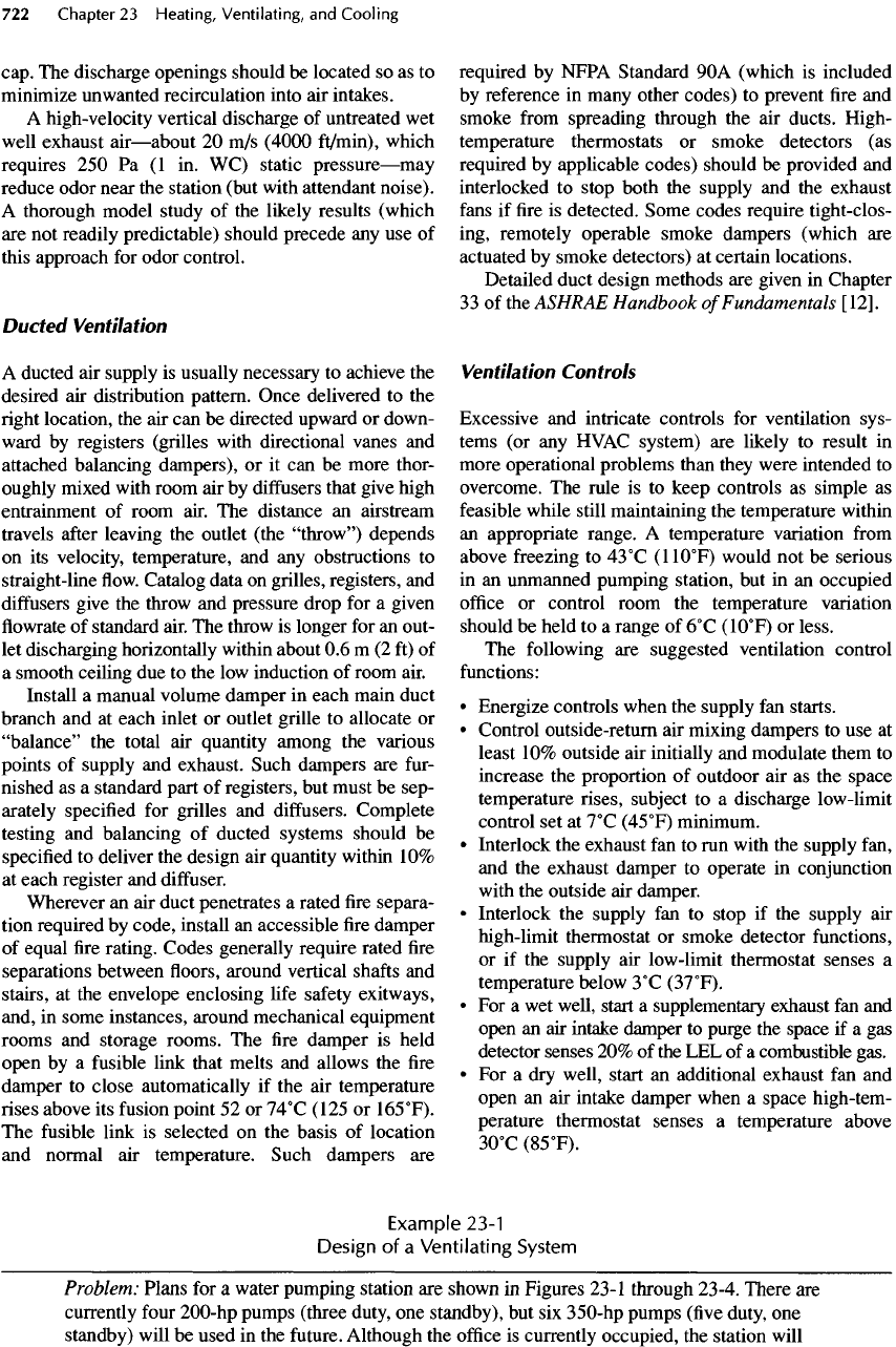
Figure
23-1.
Basement
plan.
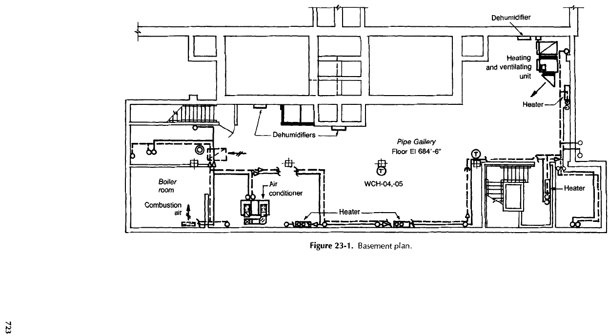
Figure
23-2. Ground-level floorplan.
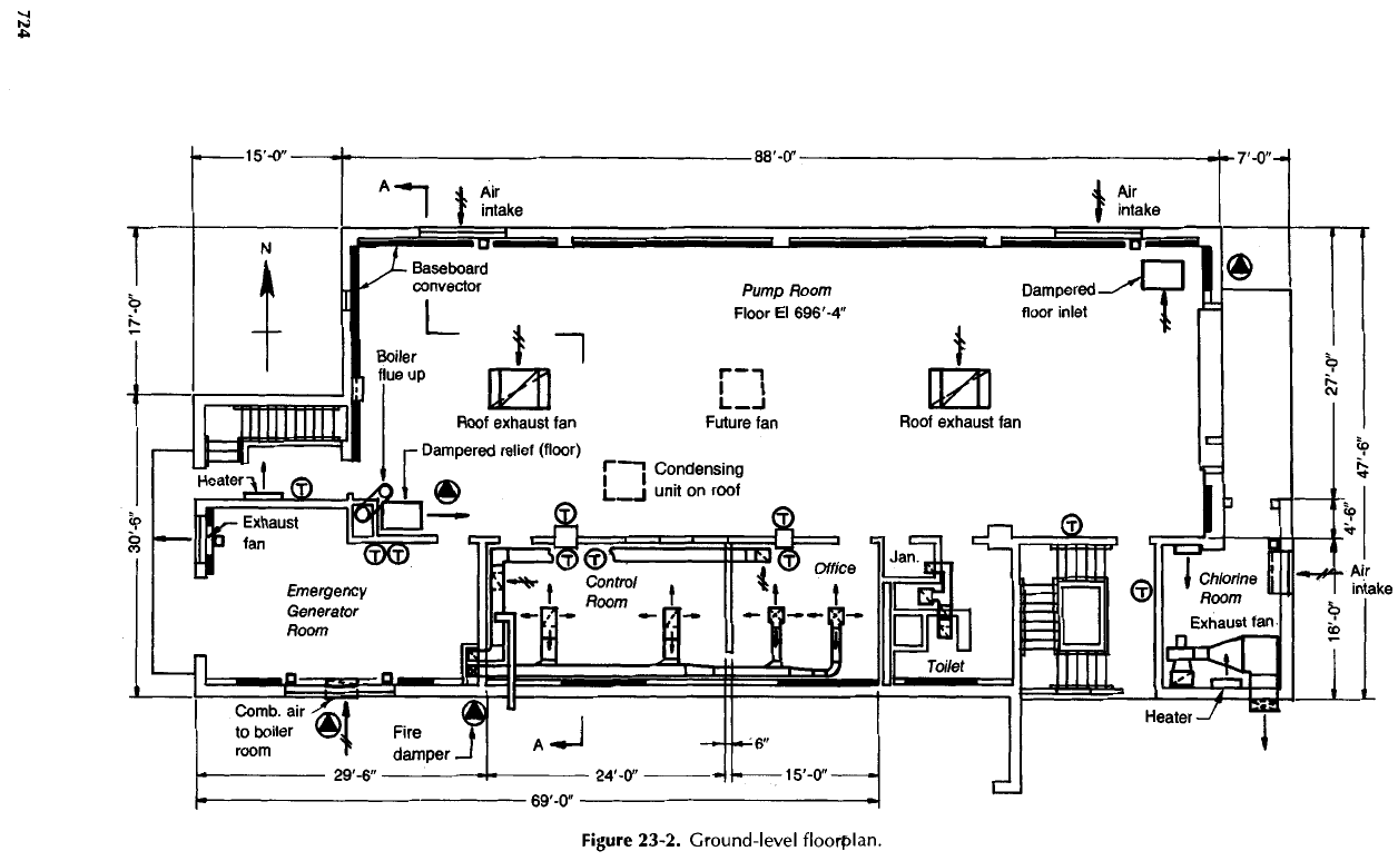
Figure
23-3. Boiler
room
plan.
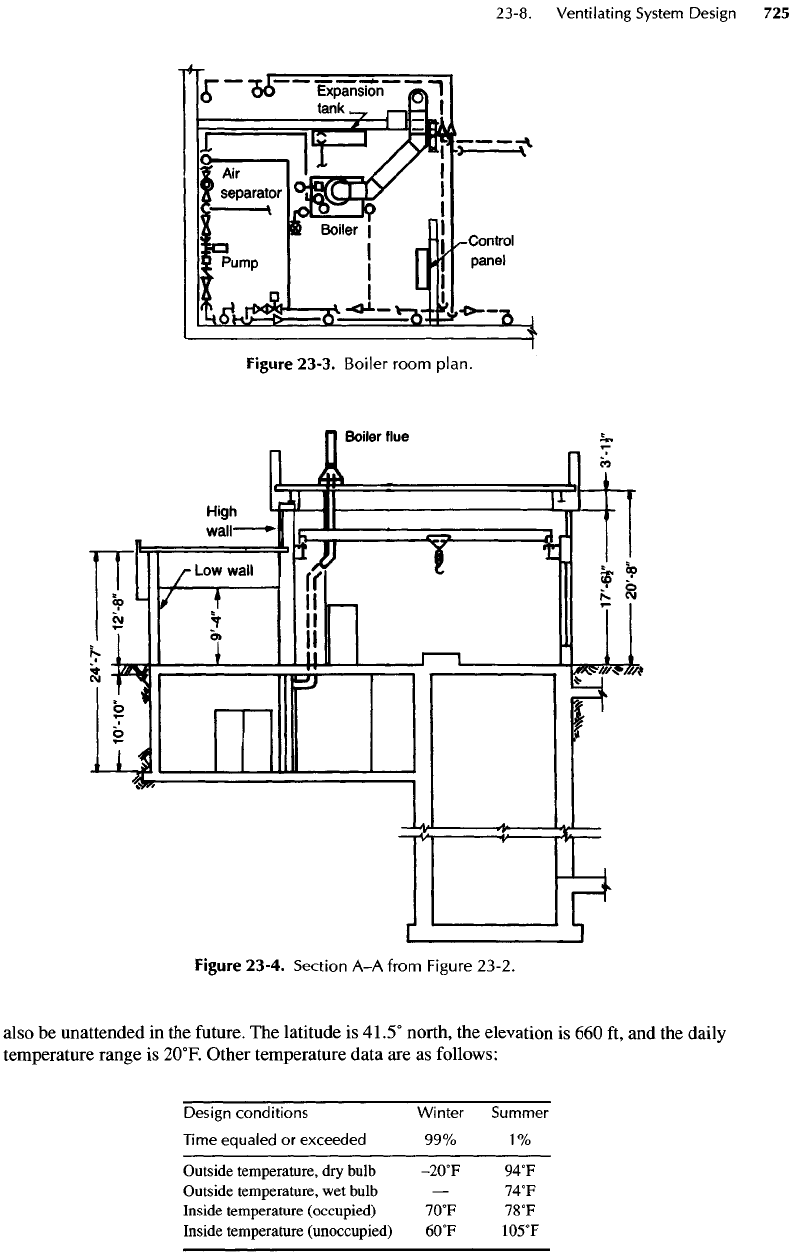
Figure
23-4. Section
A-A
from
Figure 23-2.
also
be
unattended
in the
future.
The
latitude
is
41.5° north,
the
elevation
is 660 ft, and the
daily
temperature
range
is
2O
0
F.
Other temperature data
are as
follows:
Design
conditions Winter
Summer
Time
equaled
or
exceeded
99%
1%
Outside temperature,
dry
bulb
-2O
0
F
94
0
F
Outside temperature,
wet
bulb
—
74
0
F
Inside temperature (occupied)
7O
0
F
78
0
F
Inside temperature (unoccupied)
6O
0
F
105
0
F
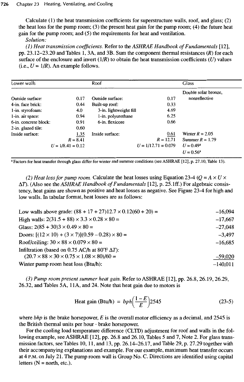
Calculate
(1) the
heat transmission
coefficients
for
superstructure walls, roof,
and
glass;
(2)
the
heat loss
for the
pump room;
(3) the
present heat gain
for the
pump room;
(4) the
future
heat
gain
for the
pump room;
and (5) the
requirements
for
heat
and
ventilation.
Solution:
(1)
Heat transmission
coefficients.
Refer
to the
ASHRAE
Handbook
of
Fundamentals
[12],
pp.
23.12-23.20
and
Tables
1,
3A,
and 3B. Sum the
component thermal resistances
(R) for
each
surface
of the
enclosure
and
invert
(1
/R)
to
obtain
the
heat transmission
coefficients
(LO
values
(i.e.,
U -
l/R).
An
example follows.
Lower
walls
Roof Glass
Double
solar
bronze,
Outside
surface:
0.17
Outside
surface:
0.17
nonreflective
4-in.
face
brick:
0.44
Built-up
roof:
0.33
1-in.
styrofoam:
4.0
3-in.
lightweight
fill
4.69
1-in.
air
space:
0.94 1-in.
polyurethane
6.25
6-in.
concrete
block:
0.91 6-in.
flexicore
0.66
2-in.
glazed
tile:
0.60
Inside
surface:
1.35
Inside
surface:
0.61
Winter
R =
2.05
fl
=
8.41
/?=
12.71
Summer/?
=1.79
U
=
1/8.41
=0.12
U =
1/12.71
=
0.079
U =
0.49
a
U
=
0.56
a
a
Factors
for
heat
transfer
through glass
differ
for
winter
and
summer conditions (see ASHRAE [12],
p.
27.10, Table
13).
(2)
Heat loss
for
pump room. Calculate
the
heat losses using Equation 23-4
(Q=AxUx
AT).
(Also
see
the
ASHRAE
Han
dbook
of
Fundamentals
[12],
p. 25.
Iff.)
For
algebraic consis-
tency,
heat gains
are
shown
as
positive
and
heat losses
as
negative.
See
Figure 23-4
for
high
and
low
walls.
In
tabular format, heat losses
are as
follows:
Low
walls above grade:
(88 + 17 +
27)12.7
x
0.12(60
+ 20) =
-16,094
High
walls: 2(31.5
+ 88) x 3.3 x
0.28
x 80 =
-17,667
Glass: 2(85
+
30)3
x
0.49
x 80 =
-27,048
Doors:
[(12
x 10) + (3 x
7)](0.59
-
0.28)
x 80 =
-3,497
Roof/ceiling:
30 x 88 x
0.079
x 80 =
-16,685
Infiltration
(based
on
0.75
AC/h
at
8O
0
F
AT):
(20.7
x 88 x 30 x
0.75
x
1.08
x
80)/60
=
-59,020
Winter
pump room heat loss
(Btu/h):
-140,011
(3)
Pump room present summer heat gain. Refer
to
ASHRAE [12],
pp.
26.8, 26.19, 26.29,
26.32,
and
Tables
5
A,
1IA,
and 24.
Note that heat gain
due to
motors
is
Heat gain
(Btu/h)
=
bph(^-^\2545
(23-5)
V^y
where
bhp is the
brake horsepower,
E is the
overall motor
efficiency
as a
decimal,
and
2545
is
the
British thermal units
per
hour
•
brake horsepower.
For the
cooling load temperature difference (CLTD) adjustment
for
roof
and
walls
in the
fol-
lowing
example,
see
ASHRAE [12],
pp.
26.8
and
26.10,
Tables
5 and 7,
Note
2. For
glass trans-
mission
factors,
see
Tables
10,
11,
and 13, pp.
26.14-26.17,
and
Table
29, p.
27.29 together with
their
accompanying explanations
and
example.
For our
example, maximum heat transfer occurs
at
4
P.M.
on
July
21.
The
pump room wall
is
Group
No. C.
Directions
are
identified
using capital
letters
(N =
north, etc.).
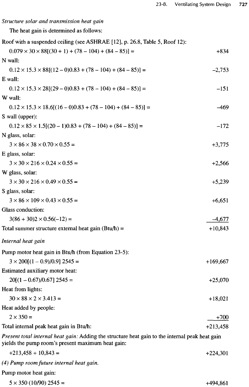
Structure
solar
and
transmission heat gain
The
heat gain
is
determined
as
follows:
Roof
with
a
suspended ceiling
(see
ASHRAE
[12],
p.
26.8,
Table
5,
Roof
12):
0.079
x 30 x
88[(30
+ 1) + (78 -
104)
+ (84 -
85)]
=
+834
N
wall:
0.12
x
15.3
x
88[(12
-
0)0.83
+
(78
-
104)
+
(84
-
85)]
=
-2,753
E
wall:
0.12
x
15.3
x
28[(29
-
0)0.83
+
(78
-
104)
+
(84
-
85)]
=
-151
W
wall:
0.12
x
15.3
x
18.6[(16
-
0)0.83
+ (78 -
104)
+
(84
-
85)]
=
-469
S
wall (upper):
0.12
x 85 x
1.5[(20
-
1)0.83
+
(78
-
104)
+
(84
-
85)]
=
-172
N
glass, solar:
3 x 86 x 38 x
0.70
x
0.55
=
+3,775
E
glass, solar:
3 x 30 x
216
x
0.24
x
0.55
=
+2,566
W
glass, solar:
3
x 30 x 216 x
0.49
x
0.55
=
+5,239
S
glass, solar:
3
x 86 x 109 x
0.43
x
0.55
=
+6,651
Glass conduction:
3(86
+
30)2
x
0.56(-12)
=
^,677
Total summer structure external heat gain
(Btu/h)
=
+10,843
Internal
heat gain
Pump motor heat gain
in
Btu/h
(from
Equation 23-5):
3
x
200[(1
-
0.9)/0.9]
2545
=
+169,667
Estimated auxiliary motor heat:
20[(1
-
0.67)/0.67]
2545
=
+25,070
Heat
from
lights:
30x88x2x3.413=
+18,021
Heat added
by
people:
2
x 350 =
+700
Total internal peak heat gain
in
Btu/h:
+213,458
Present
total internal heat gain: Adding
the
structure heat gain
to the
internal peak heat gain
yields
the
pump
room's
present maximum heat gain:
+213,458
+
10,843
=
+224,301
(4)
Pump room future internal heat gain.
Pump
motor heat gain:
5 x 350
(10/90) 2545
=
+494,861