Pumping Station Desing - Second Edition by Robert L. Sanks, George Tchobahoglous, Garr M. Jones
Подождите немного. Документ загружается.

basic details,
and
designers should
use
only those that
are
appropriate
for the
specific
application.
Detailing
Reinforcement
One of the
more important considerations
in
design-
ing
reinforcing
at
corners
and
other intersections
is
maintaining adequate clearance between bars
to
per-
mit
concrete placement that produces
a
watertight
structure. Honeycombing
or
rock pockets promote
leakage. Vertical construction joints should usually
be
located
at
least
1 to 1.5 m (3 to 5 ft)
from
corners
to
allow good
bar
placement without interference
between
water
stops
and
corner reinforcing. Splice
and
development lengths
from
ACI
318
are
applicable.
The
reinforcing
for
walls designed
as
two-way ele-
ments must
reflect
the
support conditions assumed
at
the
corners. Support conditions
are
especially critical
for
walls resisting inside pressure, because
the
interior
horizontal reinforcing must
be
developed
at the
face
of
the
intersection wall.
See
"Rectangular
Concrete
Tanks"
[7] and
Figure 25-5
for
typical corner reinforc-
ing
at
intersecting walls.
Anchors
Anchoring mechanical equipment
to
concrete
is one of
the
most troublesome tasks
in
construction,
and it
requires
careful
detailing
and
superior inspection during construc-
tion
to
avoid problems. Nowhere else
are
there greater
rewards
for
care
or
costlier penalties
for
carelessness.
The
environment
for
anchorages
is
often
hostile
due to
sub-
mergence, high humidity,
and the
corrosiveness
of
sew-
age and
some waters. Generally,
it is
more economical
to
use
stainless steel
or
appropriate coatings
on
mild steel
than
to
oversize
the
material
to
allow
for
rust
and
corro-
sion.
The
labor
of
replacement
far
exceeds
the
cost
of
pre-
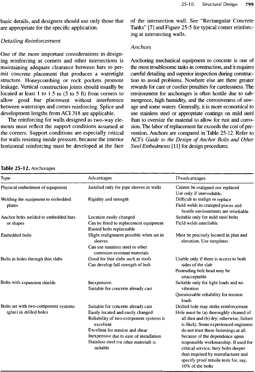
vention. Anchors
are
compared
in
Table
25-12.
Refer
to
ACFs
Guide
to the
Design
of
Anchor
Bolts
and
Other
Steel
Embedments
[1
1]
for
design procedures.
Table
25-12.
Anchorages
Type
Physical
embedment
of
equipment
Welding
the
equipment
to
embedded
plates
Anchor
bolts welded
to
embedded bars
or
shapes
Embedded bolts
Bolts
in
holes through
thin
slabs
Bolts
with expansion shields
Bolts
set
with two-component systems
(glue)
in
drilled holes
Advantages
Justified
only
for
pipe sleeves
in
walls
Rigidity
and
strength
Location
easily changed
Can be
fitted
to
replacement equipment
Rusted
bolts replaceable
Slight realignment possible when
set in
sleeves
Can
use
stainless steel
or
other
corrosion-resistant materials
Good
for
thin slabs such
as
roofs
Can
develop
full
strength
of
bolt
Inexpensive.
Suitable
for
concrete
already cast
Suitable
for
concrete already cast
Easily
located
and
easily changed
Reliability
of
two-component systems
is
excellent
Excellent
for
tension
and
shear
Inexpensive
due to
ease
of
installation
Stainless steel
(or
other material)
is
suitable
Disadvantages
Cannot
be
realigned
nor
replaced
Use
only
if
unavoidable.
Difficult
to
realign
or
replace
Field welds
in
cramped places
and
hostile environments
are
unreliable
Suitable
only
for
mild steel bolts
Field
welds unreliable
Must
be
precisely located
in
plan
and
elevation.
Use
templates
Usable only
if
there
is
access
to
both
sides
of the
slab
Protruding
bolt head
may be
unacceptable
Suitable only
for
light loads
and no
vibration
Questionable reliability
for
tension
loads
Drilled hole
may
strike reinforcement
Hole must
be (a)
thoroughly cleaned
of
all
dust
and (b)
dry; otherwise,
failure
is
likely. Some experienced engineers
do not
trust these fastenings
at all
because
of the
dependence upon
responsible workmanship.
If
used
for
critical service, bury bolts deeper
than
required
by
manufacturer
and
specify
proof tensile tests for, say,
10%
of the
bolts
Adjacent
Structures
There
are
often
ancillary structures
on
shallow
foun-
dations adjacent
to the
pumping station. They might
include small generator rooms, hydropneumatic tanks,
or
valve vaults. Their foundations should
be
designed
to
accommodate
the
mechanical
or
piping connections
between
the two
structures.
The
pumping station
is
usually
deep, whereas
the
adjacent structures usually
rest upon
backfill,
thus creating
a
perfect scenario
for
differential
settlement. Consider either
(1)
designing
flexible
mechanical
or
piping connections between
the
structures
or (2)
supporting
the
ancillary structure
with
the
pumping station itself
by
using,
for
example,
a
cantilevered counterfort.
Provision
for
Future
Expansion
When designing pumping stations, always consider
the
likelihood
of
future
expansion
and
discuss
the
potential
for
increasing
the
size
of
pumping equip-
ment with
the
owner. Provisions
can be
made
in the
original design that greatly
simplify
expansion.
Motor
or
pump
floor
systems
can be
readily
designed
for
greater
future
loads, whereas
retrofitting
an
existing marginal support system
for
higher load-
ing
can be
costly
and can
disrupt
the
operation
of the
pumping
station.
If
walls
or
slabs will
be
extended
in a
planned
expansion, waterstops
and
dowel inserts
to
facilitate
the
new
connection
can be
cast into
the
original struc-
ture
and
protected with lean concrete. Sliding
can be a
significant
problem
if the
expansion involves excava-
tion
of
soil
at the
wall
face
while
the
remaining struc-
ture
remains backfilled.
A
shear
key
(like
a
retaining
wall)
cast below
the floor
prevents sliding.
An
alterna-
tive
is to
excavate both ends
of the
below-grade
struc-
ture
to
equalize
the
soil loadings.
25-11.
Concrete Protection:
Coatings
and
Linings
Concrete structures exposed
to the
atmosphere
of
wastewater, such
as the
area above
low
water
in
sew-
ers and wet
wells,
are
attacked
and
corroded
by
sulfu-
ric
acid generated
by
bacteria.
The
mechanism
is
described
in
Section 4-7.
The
extent
of
attack
is
indi-
cated
by the pH of the
surface. Surface scrapings
of
new
concrete
in
distilled water yield
a pH
range
of
1 1
to
13. As
concrete weathers, calcium hydroxide
is
converted
to
calcium carbonate, which then slowly
dissolves
to
calcium bicarbonate. Carbon dioxide
in
the
atmosphere
can
lower
the pH to
less than
7.
SuI-
fate-reducing
bacteria
in
stale
sewage reduce
the
sul-
rate
ion in the
water
to
hydrogen
sulfide,
and
sulfide-
oxidizing bacteria
on the
walls above
the
water con-
vert
the
hydrogen
sulfide
to
sulfuric
acid, which dis-
solves components
in the
portland
cement.
The
surface
pH can be as low as
1,
but any pH of 4 or
less
indicates active corrosion.
A
protective covering
of
inert
and
impenetrable material
is
required
for
longev-
ity.
It is
better
and far
cheaper
to
apply such protection
to
new
structures than
to
repair existing ones.
The
County Sanitation Districts
of Los
Angeles
[12,
13]
have tested
a
wide variety
of
protective sys-
tems
for
many years. Systems
are
screened
by (1)
allowing
a
maker
or
supplier
to
coat
or
line
a
short,
vertical
concrete
pipe with
a
product;
(2)
partly
filling
the
pipe with
10%
sulfuric
acid;
and (3)
observing
the
effects
after
a
long period
of
time. Products that pass
this test
are
then tested under actual
field
conditions.
Concrete
Pipe
See
Section
4-7 for a
discussion
of
protection
for
con-
crete pipe.
Wet
Wells
Coatings
are
painted
on wet
well walls,
but
most coat-
ings, such
as
coal-tar
epoxy, have
not
been successful.
Because
wet
wells have many corners that
often
meet
at
odd
angles,
it is
difficult
to
apply linings. Lining
new
concrete with
PVC is,
however, about
the
only
system
that
has
provided
any
degree
of
success.
New
Construction
Unbonded, ribbed liners (such
as
T-Lock®) mechani-
cally locked into
the
concrete
during casting
are
effec-
tive
for
pipe,
but in wet
wells,
the
many joints
in
straight walls
and in
corners
as
well
as the
holes cre-
ated
by the
ties that hold
formwork
in
place require
a
great deal
of
welding
and
patching
—
the
weak points
of
the
system.
The
high quality
of
workmanship
required cannot
be
assured today.
For wet
wells,
a
bonded liner
is
better.
The
most important aspect
of
bonding liners
to
con-
crete
is the
surface
preparation.
New
concrete
is
sand
blasted
in a
pattern sweep
to
remove
laitance,
open
the
surface,
and
remove
all
debris
and
form
oil.
In the
Lina-
bond®
system,
for
example,
a
two-component primer
is
applied followed
by
trowelling
a
1.5
-mm
(60-mil)
layer
of
polyurethane
mastic.
An
activator
is
applied
to
a
sheet
of PVC and
allowed
to
cure
for a few
minutes.
The
sheet
is
then applied
to the
mastic,
and air
bubbles
are
rolled out. Joints
are
overlapped
100 mm (4
in.).
Rehabilitation
It
is
necessary
to
remove
all
damaged concrete
to
hard
gray
concrete with
a
surface
pH of at
least
7 by
using
a
water
blast
at
preferably
55,000
to
69,000
kPa
(8000
to
10,000
lb/in.
2
)
pressure
or by
sand blasting.
If
there
is
a
delay
after
water blasting,
a
sweep sand blast
is
needed.
The
surface
can
then
be
rebuilt
to its
original
contour
with,
for
example,
a
polymer grout that
is
chemically impervious
to
acid. With Linabond®,
the
polyurethane mastic
is
applied
in a
layer twice
as
thick
as for new
construction
to
allow
for a
wavy
surface.
Other
Products
There
are a
myriad
of
products
for
protecting concrete,
and
engineers should
be
alert
for
good,
new
ones.
Be
wary
and
very skeptical
of
sales claims, however,
because systems that
are
excellent
in the
laboratory
may
be
disappointing
in the field.
Furthermore,
the
traditional low-bid approach
for
choosing
a
contractor
is
not
conducive
to
good
field
work. However contrac-
tors
are
chosen, competent inspection
is
important
in
producing quality work.
It
is
best
to
investigate
field
installations that have
been
in
place several years before specifying
a
product.
Inspections
of field
applications
by the
County
Sanitation Districts
of Los
Angeles indicate there
are
no
fail-safe
coatings, even though some (polyester
mortar,
polyurea,
and a
sulfur
concrete) have with-
stood
the 10%
sulfuric
acid test well.
The
only sys-
tem
that
has a
long-term (more than
four
decades)
history
of
protection
in a
corrosive environment
is
formed-in-place
PVC
liners,
but
proper welding
of
the
seams
is
critical
for
success. Combinations
of
both coating (polyurethane mastic)
and PVC
lining
have
a
shorter history
of
success,
but
mastic with
polyethylene
linings failed
in
bond. Evaluations
are
continuing,
and it
would
be
premature
to
draw irre-
futable
conclusions yet.
25-12.
Force
Main
Design
The
force main
is not
part
of a
pumping station,
but
because
the
station curve depends
on the
friction head
as
well
as the
static head,
the
discharge piping system
cannot
be
ignored. Furthermore,
the
design
of the
force
main
affects
water hammer
or
hydraulic tran-
sients, which,
in
turn, have
an
influence
on the
design
of
the
pumping station.
Hydraulic Transients
Transient control receives
far too
little attention.
Hence, there have been many dramatic disasters
from
the
cracking
of
valves
or
pump casings
to the
rupture
of
pipes resulting
in flooding
and,
at
times,
loss
of
life.
Pump start-up with
a
force main
full
of
water causes
surges that
may
become major
for
pumps with
a
high
shutoff
head. Broken mains, damaged check valves,
distorted pump
shafts,
or a
multitude
of
small leaks
caused
by
loose joints
and
cracks resulting
from
repeated water hammer impacts
are the
result.
Transient analyses
are
usually required when
the
following
conditions exist:
• The TDH is
greater than
12 to 15
m
(40 to 50 ft)
and
the flow
exceeds about
110
m
3
/h
(500
gal/min).
•
Pipelines have high points
or
"knees"
near
the
mid-
point. Power failures
can
cause
a
partial vacuum
at
the
knee
or can
even result
in
column separation
(with
only water vapor
in the
pipe
at the
knee)
—
a
problem
to
avoid
at all
costs.
• The
static pressure differential
for an
in-line booster
pump
is
more than
12m
(40
ft).
Transient analyses
are not
usually required
if (1)
the
total
TDH is
less than
12 m (40
ft),
(2) the flow is
less than
23
mm
3
/h
(100 gal/min),
(3) the
pipe veloc-
ity
is 0.6
m/s
(2
ft/s)
or
less,
or (4) the
pumps dis-
charge into
a
domestic water network. Such networks
have
many branches
and
loops
to
dissipate
the
tran-
sients.
See
Chapters
6 and 7 for
more explanation.
Simplified
transient analyses
may be
incorrect
or
mis-
leading. Computer modeling
is the
most
effective
method,
and
the
cost
for an
experienced consultant
can
range
from
about
$1000
for a
simple system
to
$10,000
or
more
for a
complex
problem. Some
manufacturers
and
suppliers
offer
computer modeling
as a
free
service,
but as
such
modeling
may be
incomplete
or
biased,
the
user
had
better
know
how to
review
the
assumptions
and the
results.
There
are
many methods
for
controlling transients,
but
none
can be
used indiscriminately.
For
example,
the
pipe
profile
dictates both
the
kind
and
placement
of
hardware. Only
an
expert should make
the
analysis
and
design
the
transient control system.
Size
Optimize
the
size
of the
pipe based
on the
life-cycle
cost, including power
and
capital costs.
A
practical
maximum
velocity
is
about
2.4 m/s (8
ft/s). Higher
flow
results
in
greater headlosses
and may
result
in
excessive water hammer.
The
lowest design veloc-
ity
that should
be
used
for raw
sewage
is 0.6 m/s
(2
ft/s)
to
keep grit moving,
and a
peak daily veloc-
ity
of
1.1
m/s
(3.5 ft/s)
is
desirable
to
resuspend set-
tled solids.
Friction
Coefficient
Use the
correct friction coefficients
for
pipes.
Exces-
sively
rough
friction
factors, although conservative
with
respect
to the
carrying capacity
of the
pipe,
are
dangerous
for the
selection
of
motors
and
pumps (see
Section 3-2). When determining
the
carrying capac-
ity,
a
conservative practice
is to use C =
120
for
lined
or
plastic pipe
(or C =
100
for
unlined pipe), which
conforms
to
Ten-State Standards; then redraw
the
system
curve
for C =
145. Make sure that
the
system
can
operate
at
both conditions
or at any
intermediate
condition.
25-13.
References
1.
Crites,
R.,
and G.
Tchobanoglous. Small
and
Decentralized
Wastewater
Management Systems,
McGraw-Hill,
Inc.
New
York
(1998).
2.
Tchobanoglous,
G.,
and F. L.
Burton.
Wastewater
Engineering:
Treatment,
Disposal, Reuse,
3rd
ed.,
McGraw-Hill,
New
York
(1991).
3.
Metcalf
and
Eddy,
Inc.
Wastewater
Engineering:
Collection
and
Pumping
of
Wastewater,
edited
by G.
Tchobanoglous, McGraw-Hill,
New
York
(1981).
4.
WEF.
Design
of
Municipal
Wastewater
Treatment
Plants, Manual
of
Practice
No. 8,
Vol.
1,
Water
Environment
Federation, Alexandria,
VA
(1991).
5.
ASCE.
Gravity
Sanitary
Sewer Design
and
Construction,
ASCE Manuals
and
Reports
on
Engineering
Practice
No. 60,
American Society
of
Civil Engineers,
New
York
(1982).
6.
Nuclear Reactors
and
Earthquakes.
Chapter
6 and
Appendix
F.
Technical Information Document
7024,
Lockheed Aircraft Corp. (1963).
7.
"Rectangular Concrete Tanks,"
Information
Sheet
ISOO3.03D, Portland Cement Association, Skokie,
IL
(1969
Rev.
1981).
8.
Moody,
W. T.
"Moments
and
reactions
for
rectangular
plates,"
Engineering Monograph
No. 27.
U.S.
Bureau
of
Reclamation, Denver,
CO
(1960
Rev. 1963).
9.
Housner,
G. W.
"The
dynamic behavior
of
water
tanks,"
Bulletin,
Seismological Society
of
America,
53
(2):
381-387
(1963).
10.
Housner,
G. W.
Earthquake
Pressures
on
Fluid
Containers,
California Institute
of
Technology,
Pasadena,
CA
(1954).
11.
ACI.
Guide
to the
Design
of
Anchor Bolts
and
Other
Steel
Embedments,
AB-81,
American Concrete
Institute,
Farmington
Hills,
MI
(1981).
12.
Redner,
J.,
R.
Hsi,
and E.
Esfandi. "Evaluating coatings
for
concrete wastewater facilities:
An
update"Journal
of
Protective Coatings
and
Linings,
11
(12):
50-161
(December 1994).
13.
Redner,
J.,
R.
Hsi,
and E.
Esfandi. "Evaluating coatings
for
concrete exposed
to
sulfide
generation
in
wastewater
treatment
facilities," Journal
of
Protective
Coatings
and
Linings,
8(11):
48-56
(November
1991).
Chapter
12
contains details
for
selecting pumping
equipment
and
installing
it in
properly designed
wet
wells
with
piping arrangements that allow
for
easy
access
in a
minimum
of
space.
The
principles
for the
layout
of the
basic elements
of
wastewater
and
water
pumping
stations respectively
are
given
by
example
in
Chapters
17 and
18.
These principles should
be
fol-
lowed with
an
overall objective
to
keep
the
installation
as
simple
as
possible.
The
guiding rule should
be to
provide protection
for the
equipment
and
installation
and,
as
much
as
practicable, protection against
the
prospect
of
catastrophic
failure.
Care should
be
exer-
cised
to
follow
the
requirements
of
appropriate code
documents
and
industry standards.
This chapter contains examples
of
both actual
and
hypothetical designs that
reflect
improvements
in
technology that have occurred since publication
of the
first
edition
of
Pumping Station Design
in
1989.
The
examples
of
pumping station design include:
Chapter
26
Pumping
Station
Design
Examples
GARR
M.
JONES
GARY
S.
DODSON
THEODORE
B.
WHITON
CONTRIBUTORS
Roger
Cronin
Philip
A.
Huff
Paul
C.
Leach
Ralph
E.
Marquiss
M.
Steve
Merrill
Earle
C.
Smith
Patricia
A.
Trager
William
Wheeler
•
Section 26-1. Duplex submersible pumps
for
domestic wastewater
in a
hopper-bottom sump.
Capacity: 25.9
L/s
(410
gal/min).
Improvement
of
original design.
•
Section 26-2. Three dry-pit,
V/S
pumps
for
domestic
wastewater
in a
trench-type sump.
Capacity:
219 L/s
(5
Mgal/d).
Improvement
of
original design.
•
Section 26-3. Three
four-
stage,
two-speed vertical
turbines
for raw
water
in a
trench-type sump.
Capacity:
920 L/s (21
Mgal/d). Designed
in
1993,
and
began service
in
1995.
•
Section 26-4. Three submersible pumps with long
suction nozzles
in a
trench-type sump
for
combined
sewage
overflow
(CSO) service. Capacity:
227 L/s
(5.2 Mgal/d). Construction virtually complete
in
January
1998.
Dimensions
and
values
in the
plans
and
text
for
each
section are,
for
simplicity, written
in
either
SI
units
or in
U.S. customary units
but not
usually
in
both.
Readers should have
no
difficulty
in
transforming
one set of
units into
the
other.
26-1
.
Redesigned Clyde
Wastewater
Pumping
Station
The
Clyde Wastewater Pumping Station
in
Contra
Costa County, California,
was
rebuilt
in
1991
to
fea-
ture
a
self
-cleaning
sump.
It is
cleaned
by
pumping
the
water level down while vigorously mixing
the
contents
with
water
from
the
force main.
In the as-
built
plans, shown
in
Figure 17-22, eccentric plug
valves
in the
valve vault
can be
regulated
to
take water
from
either
the
force main
or
from
either
of the two
pumps.
The
water
is
discharged under considerable
pressure
at the
surface
of the
lowered water level
in
the
sump while
a
pump discharges
the
mixed liquid
to
the
force
main.
The
system works well
for
removing
both scum
and
sludge
and
leaves
the wet
well remark-
ably
clean.
In
this section,
the
station
is
described
as it
might
be
designed
in
1997 with
the
technology developed
since
the
original plans were drawn. These changes
consist
of (1)
steeper slopes
to
allow sludge
to
slide
down
to the
pump intakes
so
that sludge
is
removed
with
every motor start
and (2) a
sloping approach pipe
for
introducing
the
inflow
without
a
cascade
and for
supplying
added storage
to
reduce
the
size
of the wet
well.
In
other respects,
the
design approach closely
follows
that
of the
existing Clyde pumping station
except that
fewer
valves
are
used
in the
valve vault.
The
actual design
was
carried
out in
U.S. custom-
ary
units,
so
those
are the
units used
in
this example.
The
original sewer design studies, surveys,
and
dis-
cussions with operating
and
maintenance
staff
estab-
lished
the
following general
requirements
for
this
sewage
lift
station:
•
General: submersible pumps were preferred
because
of
overall
low
cost,
low
maintenance, sim-
plicity
in
operation,
and
minimizing visual impact
on
the
neighborhood.
•
Flowrates:
Present average
dry-
weather
flow:
30
gal/min.
Present peak
wet-
weather
flow: 236
gal/min.
Future
peak
wet-
weather
flow: 410
gal/min
(equals
the
capacity
of one
pump).
•
Ground elevation: 13.2
ft.
Pumping station site
is
relatively
flat.
•
Force main:
An
existing 8-in. cement-lined ductile
iron pipe 2750
ft
long
was
available.
Invert
elevation:
6.6 ft at the
pumping station
and
20.6
ft at the
discharge.
Slope:
constant.
•
Reliability: ability
to
pump
future
peak wet-weather
flow
with
either
of the two
pumps
out of
service.
Hook-up
for
portable engine-generator
due to
lack
of
space
for
permanent engine-generator.
High
wet
well power-failure
and
intrusion alarm
hooked
up to an
auto-dialer.
•
Location:
on
shoulder
of
narrow residential street.
Considerations
include space, visibility, odors,
noise,
and
security.
Station
Siting
Station siting
is
established
by the low
point
in the
tributary area
as
well
as
access, availability
of
prop-
erty, proximity
to
residents
(i.e.,
farther
is
better),
and
the
cost
of
piping
to and
from
the
site.
The low
point
in
the
tributary area usually dictates
the
general loca-
tion. Access
is
important because operation
and
main-
tenance
staff
must
be
able
to
visit
the
facility
at any
hour
of the day and
under adverse conditions. Access
by
public roads (paved,
if
possible)
without
the
need
to
traverse private property
or
move parked automo-
biles
is
required.
It is
also preferable
to
provide room
for
maintaining
the
station without obstructing
traffic
or
endangering workers.
Property
and
easement acquisition begins immedi-
ately
after
selecting
the
preferred site
and
before
design
on the
pump station begins. Many projects
have
been delayed and/or designs changed because
the
site acquisition process
did not
begin soon enough.
Such delays
and
changes will result
in
significant
costs
to the
owner
of the
facility.
Hydraulic Design
Hydraulic design includes sizing
the
force main
and
developing
the
system curves, which
are
then used
to
select
the
number
and
size
of the
pumps.
The
rest
of
the
facility
is
designed around
the
pumps.
The
force
main invert elevation
at the
pumping station should,
if
possible,
be set to
allow
for a
constantly
rising
slope.
High spots (knees)
in a
wastewater force main
are to
be
avoided
if at all
possible, because knees require
air
release valves, which clog with grease
and
require
constant maintenance. (Some utilities regularly
replace
all
working parts with shop-cleaned parts
every month.)
Force
main installation costs increase
with
depth,
so it is
best
to
keep
the
pipe
as
shallow
as
possible.
The
discharge
end of the
force main
is
sus-
ceptible
to
hydrogen
sulfide
corrosion
and
should
be
protected
by
using corrosion resistant piping (PVC,
HDPE, VCP) where exposed
to air or
else
be
sub-
merged
to
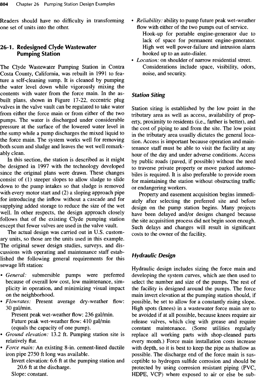
prevent corrosion. Corrosion resistant
pip-
ing,
as
shown
in
Figure
26-1,
should begin
10 ft
before
the
point where
the
static water level contacts
the
soffit
of the
force main.
Force mains should
be
sized
to
provide
a
minimum
velocity
of 2.5
ft/s
at
present
flows and a
maximum
velocity
of 6 to 8
ft/s
at
future
peak
wet
weather
flows.
The
minimum velocity
ensures
that most
solids
will
be
moved through
the
force main.
The
maximum
velocity
is set to
minimize headless
and
reduce surge
pressures
in
long force mains.
A
6-in.
force main
would
meet this criteria
for the
stated
flow
conditions.
However,
an
8
-in.
mortar-lined ductile iron
pipe
was
already
in
place
and
was, therefore, used.
The
velocity
in
the
force main
for
this pumping station
with
its one
duty
pump
is 2.5
ft/s
(see
Table
B-2 for the
cross-sec-
tional area).
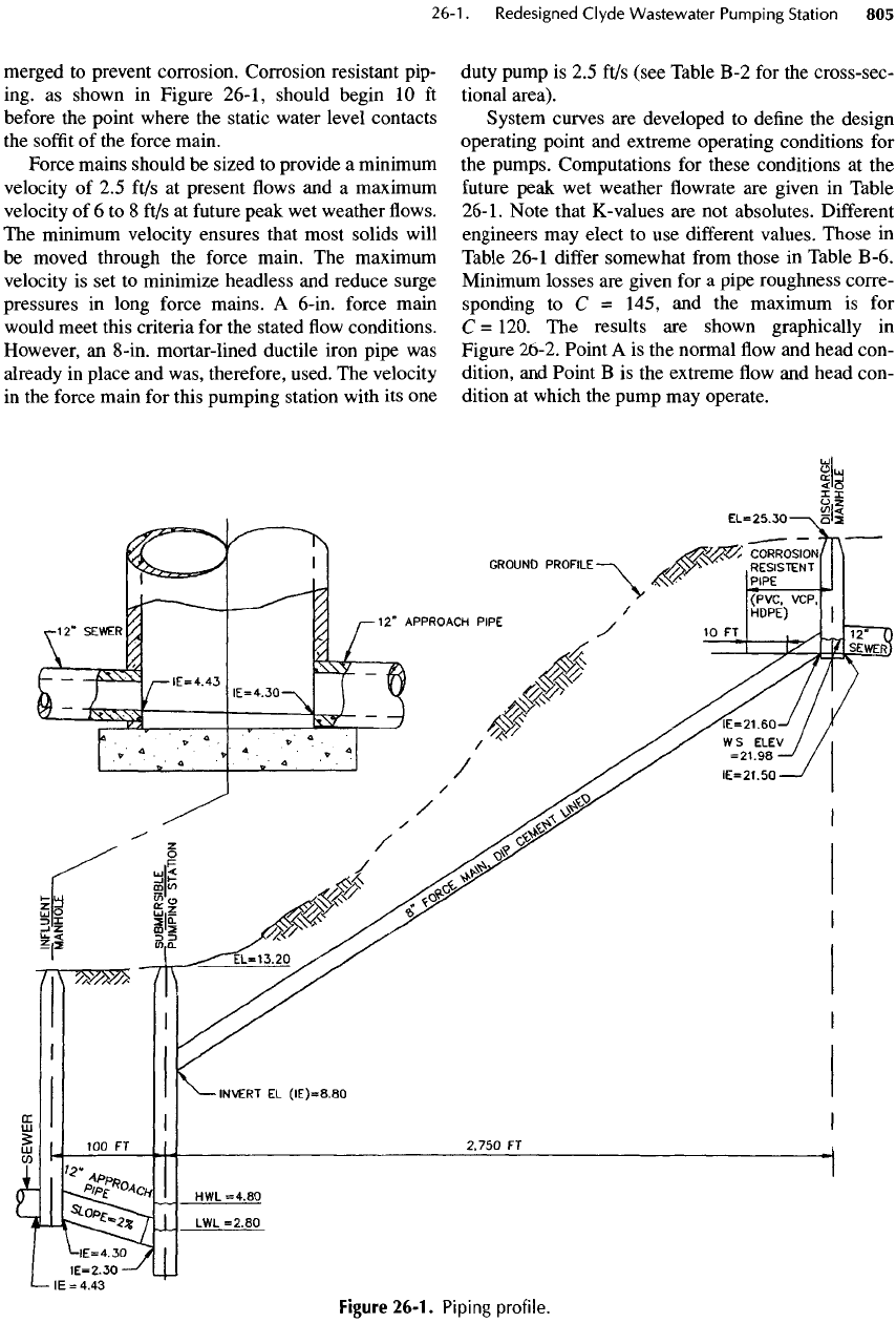
System curves
are
developed
to
define
the
design
operating
point
and
extreme operating conditions
for
the
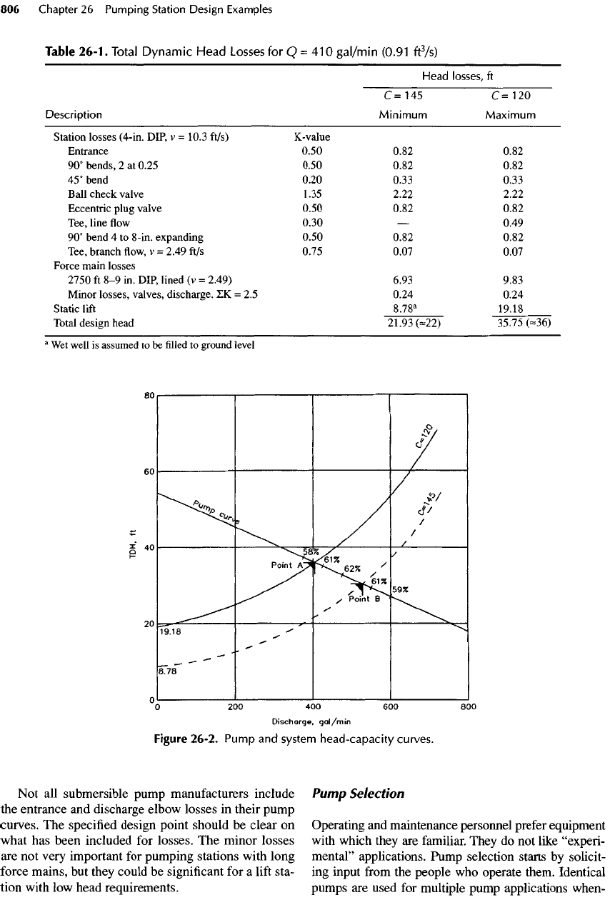
pumps. Computations
for
these conditions
at the
future
peak
wet
weather
flowrate are
given
in
Table
26-1. Note that
K-
values
are not
absolutes.
Different
engineers
may
elect
to use
different
values.
Those
in
Table
26-1
differ
somewhat
from
those
in
Table
B
-6.
Minimum losses
are
given
for a
pipe roughness corre-
sponding
to C =
145,
and the
maximum
is for
C =
120.
The
results
are
shown graphically
in
Figure 26-2. Point
A is the
normal
flow and
head con-
dition,
and
Point
B is the
extreme
flow and
head con-
dition
at
which
the
pump
may
operate.
Figure
26-1.
Piping profile.
Not
all
submersible pump manufacturers include
the
entrance
and
discharge elbow losses
in
their pump
curves.
The
specified design point should
be
clear
on
what
has
been included
for
losses.
The
minor losses
are not
very important
for
pumping stations with long
force
mains,
but
they could
be
significant
for a
lift
sta-
tion
with
low
head requirements.
Pump
Selection
Operating
and
maintenance personnel prefer equipment
with
which they
are
familiar. They
do not
like
"experi-
mental" applications. Pump selection starts
by
solicit-
ing
input
from
the
people
who
operate them. Identical
pumps
are
used
for
multiple pump applications when-
Figure
26-2.
Pump
and
system head-capacity curves.
Table
26-1.
Total
Dynamic Head
Losses
for
Q=
410
gal/min
(0.91
ft
3
/s)
Head
losses,
ft
C=
145
C=
120
Description
Minimum
Maximum
Station
losses
(4-in.
DIP,
v =
10.3
ft/s)
K-value
Entrance
0.50 0.82 0.82
90°
bends,
2
at
0.25 0.50 0.82 0.82
45°
bend
0.20 0.33 0.33
Ball check valve
1.35 2.22 2.22
Eccentric
plug valve
0.50 0.82 0.82
Tee,
line
flow
0.30
—
0.49
90°
bend
4 to
8-in.
expanding
0.50 0.82 0.82
Tee, branch
flow, v =
2.49
ft/s
0.75 0.07 0.07
Force
main losses
2750
ft 8-9 in.
DIP,
lined
(v =
2.49) 6.93 9.83
Minor losses, valves, discharge.
IK = 2.5
0.24 0.24
Static
lift
8.78
a
19.18
Total design head
21.93
(-22)
35.75
(-36)
a
Wet
well
is
assumed
to be filled to
ground level
ever
possible
to
simplify
maintenance
and
provide
interchangeability
of
parts.
It is
advantageous
to
have
service
and
parts available
from
a
nearby source.
The
selected pump curve
and
impeller diameter
should meet
the
design point near
the
best
efficiency
point.
The
selected pump should also operate
at the low
head
and
high head extremes without
cavitating
or
vibrating. Pump curves
with
steep slopes
are
better
than
those
with
flat
slopes, because there
is
less variation
in
capacity
with
varying head conditions. (Flat spots
or
dips
in
the
pump curve
are
therefore undesirable.) Wherever
possible choose impellers
of
intermediate size
so
that
a
larger
impeller
can be
substituted
for
larger
future
flows.
The
motor
is
sized
for the
worst possible operating point
(which
is
often
the low
head extreme
with
one
pump
operating).
For
multiple pumps,
the
best pump
efficiency
should
be at
normal operating conditions
and not at the
ultimate
peak
flows.
However,
the
emphasis should
be
on
finding
pumps that
can
operate without vibration
or
cavitation
at all
anticipated service conditions.
Wet
Well
The wet
well
is
designed
to (1)
provide adequate space
for
the
pumps;
(2)
facilitate cleaning;
(3)
contain
suffi-
cient storage volume;
(4)
limit pump starts;
and (5)
minimize installation costs.
For a
small duplex sub-
mersible pump station
the
most economical
wet
well
is
often
a
reinforced concrete pipe
1.8
or 2.4
m
(6 or 8 ft)
in
diameter standing
on a
cast concrete bottom.
To
improve solids removal,
the
pumps
are
confined
by
close-fitting,
nearly conical, smooth walls sloping
at 45°
to 60°
(preferably
the
latter). Sludge
and
grit slide down
the
walls
to the
pump suction.
If the floor is a
minimum
size (about
0.6 x 1.2 m or 2 x 4 ft), the
sludge
is so
con-
fined
that
most
of it is
pumped
out on
each pump cycle.
The
sloping walls
may be
constructed
by
placing
a
custom
form
in the wet
well
and
injecting concrete
behind
the
form.
Fiberglass reinforced plastic
or
stain-
less steel
can be
used
as the
form
and can
then remain
in
place
as a
liner
to
provide
a
smooth, corrosion-
resistant surface
to
facilitate cleaning. Holes
are
required
in the
form
for the
pump discharge elbows,
which
are
cast into
the
walls.
If a
disposable
form
is
used,
the
concrete should
be
covered with
a
protective
liner such
as
PVC.
The
vertical walls above
the
"cone"
should also
be
protected with
a PVC
liner.
Active
Volume
The
active
or
working volume
of wet
well
and
approach pipe must
be
adequate
to
limit
the
frequency
of
pump starts
to a
safe
value. Conical bottoms reduce
the
volume available
in the wet
well,
but the
addition
of
an
approach pipe laid
on a 2%
gradient,
as
described
in
Section 12-7, supplies additional volume.
The
normal
LWL is set
above
the
invert
of the
inlet
so
that there will
be no
free
fall
into
the wet
well.
Consult
the
manufacturer about
the
minimum submer-
gence
for the
motor
and the
maximum
frequency
of
pump starts. Typically,
the
motor should
be
about half
submerged
at
LWL, although under some circum-
stances
the
allowable submergence might
be
less.
Starting
frequency
for
small
to
medium-size submers-
ible pumps
may be
expected
to
vary between
6 and
15
starts/h.
Using
an
alternator
in
stations with multiple
pumps
to
switch lead pumps
after
each pump cycle
reduces
the
starting
frequency.
However,
one
pump
may
be out of
service,
so
duplex stations must
be
operable without alternation. Nevertheless, when both
pumps
are
serviceable, alternation could
be
used
to
extend
the
life
of the
starters
and
motors.
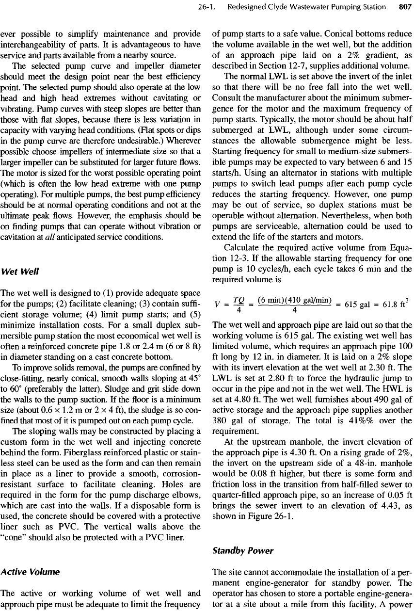
Calculate
the
required active volume
from
Equa-
tion
12-3.
If the
allowable starting
frequency
for one
pump
is 10
cycles/h,
each cycle takes
6 min and the
required volume
is
v
=
TQ
_
(6
min)(410
gaVmin)
_
^
_
^
ft
s
44
The wet
well
and
approach pipe
are
laid
out so
that
the
working volume
is 615
gal.
The
existing
wet
well
has
limited volume, which requires
an
approach pipe
100
ft
long
by 12 in. in
diameter.
It is
laid
on a 2%
slope
with
its
invert elevation
at the wet
well
at
2.30
ft. The
LWL is set at
2.80
ft to
force
the
hydraulic jump
to
occur
in the
pipe
and not in the wet
well.
The HWL is
set at
4.80
ft. The wet
well
furnishes
about
490 gal of
active storage
and the
approach pipe supplies another
380 gal of
storage.
The
total
is
41%%
over
the
requirement.
At
the
upstream manhole,
the
invert elevation
of
the
approach pipe
is
4.30
ft. On a
rising grade
of 2%,
the
invert
on the
upstream side
of a
48-in. manhole
would
be
0.08
ft
higher,
but
there
is
some
form
and
friction
loss
in the
transition
from
half-filled
sewer
to
quarter-filled
approach pipe,
so an
increase
of
0.05
ft
brings
the
sewer invert
to an
elevation
of
4.43,
as
shown
in
Figure
26-1.
Standby
Power
The
site cannot accommodate
the
installation
of a
per-
manent engine-generator
for
standby power.
The
operator
has
chosen
to
store
a
portable engine-genera-
tor at a
site about
a
mile
from
this
facility.
A
power
failure
and
high water alarm provide indication
of
potential
overflow
at the
station. During
dry
weather
flow,
more than
one
hour
is
available
to
transport
and
connect
the
portable engine-generator. However, dur-
ing
wet
weather
periods,
there
may be
less than
10
min
available
for
that task. Wastewater pumping sta-
tions should normally
be
provided with permanent,
on-site standby power
to
reduce
the
exposure
to
wastewater
overflows.
Station
Piping
Station piping within
the wet
well
is
limited
to the two
pump
discharge lines
and a
force main drain line. Pip-
ing
within
the wet
well
is as
simple
as
possible with
few
fittings and no
valves.
All flange
bolts within
the
wet
well
are 316
stainless steel,
as are the
pipe sup-
ports
and
hardware.
The
piping design within
the wet
well
minimizes items that corrode, that require regular
maintenance,
or
that
may
catch
floating
debris.
Valves
and
fittings are
contained
in a
separate valve
pit
next
to the wet
well.
The
valve
pit
contains
the
pump isolation
and
check
valves
on the two
pump discharge lines
and
their con-
nection
to the
force main.
A
valved force main drain
line that discharges back into
the wet
well
is
also
included.
It can be
used
to
agitate
the
contents
of the
wet
well vigorously
so
that scum, mixed into
the
con-
tents,
is
ejected with
the
wastewater. Such mixing
eliminates
the
need
to
pump
the
water level down
to
the
pump volute
to
develop vortices
for
engulfing
the
scum
—
an
operation that subjects
the
pump
to
vibra-
tion, stress
and
wear
of the
mechanical seals,
and
pos-
sible
air
binding.
Valve
stems
and
nuts
are
extended
nearly
to
grade
to
permit operation without
the
need
to
enter
the
vault.
The
plans
are
shown
in
Figure 26-3.
An
alternative
is the use of a
pump that ejects part
of
its
discharge into
the wet
well during
the first
minute
or two
after
the
pump
is
switched
on. The
water
ejected through
a flush
valve mixes
the
solids
so
that
most
are
discharged
to the
force main during each
pump
cycle.
The
advantage
is
that
the wet
well
is
kept
continuously clean automatically.
The
disadvantages
are a
small loss
of
efficiency
and the
added mechani-
cal
device located
in the wet
well.
Controls
and
Alarms
The
pumps
are set up in a
lead/lag
arrangement with
automatic
alternation
after
each pump cycle
to
balance
run
times
and
minimize starts
per
hour. HAND/OFF/
AUTO
operator selector switches
are
provided
for
each
pump
at the
control panel located with
a
view
of the wet
well. Pumps
are
operated
by the wet
well water level
indicated
by a
pressure transducer/transmitter hanging
in
a PVC
pipe
in the wet
well.
Key pad
controllers
are
generally preferred because they
are
easy
to
operate,
do
not
have pins (easy
to
lose),
and can be
programmed
with
a
security
code.
The
high water level alarm consists
of
a float
switch connected
to an
auto-dialer that pages
the
on-call
operator.
A
stainless-steel chain supported
by
the
hatch
frame
is
connected
to the float
switch
so the
operator
can
periodically test
the
switch.
A
nylon cord
would
serve
the
same purpose
at
less cost.
Operation
and
Maintenance
Double-leaf, spring-loaded aluminum hatches rated
for
an
H-20
loading
are
installed over
the wet
well
for
access
to the
pumps. Similar hatches
are
installed over
the
valve vault. Safety chains
are
provided
to
create
a
barrier when
the
hatch
is
open. Hatches
are
equipped
with
padlocks
for
protection against vandalism.
Telescoping stainless-steel tubes
are
used
for
guide
rails
for
installing
the
pumps. Except during times
needed, they
are
lifted
out of the
water
and
hence
do
not
collect debris. Stainless steel cables
are
attached
to the
pumps
for
removal
and
installation.
The
owner
uses
a
truck-mounted boom
and
winch
for
this ser-
vice, but, alternatively,
a fixed
crane
or
hoist could
be
provided
on
site. Winches
are
equipped with ratchets
for
use in
both directions.
The
site
is
equipped with overhead lights with
electric
power supplied
from
a
nearby power
service
pole.
Lights
are
also provided within
the
outer door
of
the
control panel.
A
weather guard extending
18
in. in
front
of the
panel
is
installed
at the top
front
of the
control panel.
A
hook-up with
a
manual transfer
switch makes
it
easy
to use the
owner's
trailer-
mounted
engine-generator.
Wash-down
water
is
obtained on-site
from
the
potable water supply.
The
equipment consists
of an
air-gap tank, water pump,
and
hose bibb contained
in
a
locked steel cabinet.
The
wash-water pump,
equipped with
a
preset
timer
for
automatic
shutoff,
also
has an
automatic recirculation line with
a
pres-
sure regulating valve. Steel
traffic
bollards
are
placed
around
the
water
and
electrical control cabinets.
No
fencing
is
provided around
the
site.
Final
Check
After
completing
the
pump selection
and
piping lay-
outs,
the
system hydraulics
are
checked again
to see