Qiu X.G. (Ed.) High Temperature Superconductors
Подождите немного. Документ загружается.

392 High-temperature superconductors
1
2
3
4
5
6
7
8
9
10
1
2
3
4
5
6
7
8
9
20
1
2
3
4
5
6
7
8
9
30
1
2
3
4
5
6
7
8
9
40
1
2
43X
© Woodhead Publishing Limited, 2011
Rs is a measure of the rate of energy dissipation in the surface, and the surface
reactance Xs is a measure of the peak inductive energy stored in the surface.
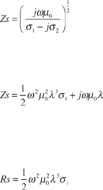
Relating to complex conductivity, surface impedance can then be written as
[10.3]
In cases where the temperature is not too close to T
c
, where more superconducting
carriers are present, and
σ
1
is finite but much smaller than
σ
2
, an approximation
of
σ
1
<<
σ
2
can be made. It then turns out that
[10.4]
with the frequency independent magnetic penetration depth
λ
= (m /
µ
0
n
s
e
2
)
1/2
,
where m is the mass of an electron and e is the charge on an electron.
From equation 10.4 important relations for surface resistance and reactance can
easily be derived:
[10.5]
and
Xs =
ωµ
0
λ
[10.6]
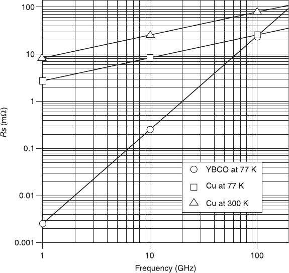
It is well known that for a normal metal surface resistance increases with
ω
1/2
,
whereas for a superconductor it increases with
ω
2
. Knowledge of the frequency
dependence of surface resistance is especially important to evaluate the potential
microwave applications of a superconductor. Hein (1999, p.93) showed a double-
logarithmic plot of surface resistance Rs versus frequency, depicting selected data
for granular and high quality epitaxial YBCO films at 77 K. It can be seen from
Fig. 10.2 that YBCO displays a lower surface resistance than Cu, up to about
100 GHz, and that the overall trend resembles that of the conventional
superconductor Nb
3
Sn films at 9 K. It can thus be concluded that the two-fluid
formalism is capable of describing all measured data over 3 decades in frequency.
10.2.2 The non-linear microwave properties of
superconductors
Non-linearity is an important phenomenon in nature, which has profound significance
for modern technology. Research into nonlinear microwave properties has revealed
a number of nonlinear phenomena, such as RF-vortex nucleation, annihilation and
motion, etc., which will bring new understanding of fundamental sciences. The
dynamics of various types of vortices behave in unique ways because the penetration
of the microwave current into the superconductor is quite different to that of d.c.
current. However, in this chapter we will concentrate our discussions on the effect of
Microwave filters using high-temperature superconductors 393
1
2
3
4
5
6
7
8
9
10
1
2
3
4
5
6
7
8
9
20
1
2
3
4
5
6
7
8
9
30
1
2
3
4
5
6
7
8
9
40
1
2
43X
© Woodhead Publishing Limited, 2011
the non-linearity of HTS materials on microwave devices, mainly in terms of the
substantial restriction of their power handling ability. The superior microwave
properties of HTS materials are only realized when the current density everywhere
within an HTS circuit is less than the critical value. If the power level of an HTS
microwave circuit is increased, the current density in the HTS material increases
accordingly. When the current density exceeds the critical value, the surface resistance
of the HTS material increases sharply, causing excessive loss in the circuit, and
eventually the performance collapses due to the transition into the non-superconducting
state. The nonlinear effects make the situation even worse. The non-optimized power
handling of HTS thin films causes the performance of potentially linear devices to
deteriorate greatly (e.g., filters, delay lines) and limits optimization of the properties
of nonlinear devices (e.g., switches, power limiters). The power handling of HTS
devices is likely to be restricted by extrinsic sources, such as growth defects and
impurities within the films, but precisely what type of defects and impurities
contribute to the nonlinear behaviour remains unclear for the time being. This is why
10.2 Frequency dependence of surface resistance Rs of high
temperature superconductor YBCO at 77 K (lowest line with symbol )
compared with normal metal Cu at 300 K (upper line with symbol △)
and 77 K (lower line with symbol ).
394 High-temperature superconductors
1
2
3
4
5
6
7
8
9
10
1
2
3
4
5
6
7
8
9
20
1
2
3
4
5
6
7
8
9
30
1
2
3
4
5
6
7
8
9
40
1
2
43X
© Woodhead Publishing Limited, 2011
nearly all modern HTS filter applications are positioned in the receiver (very low
power) side. However, the demand for HTS filters with higher power handling
ability, is increasing all the time (e.g., for applications of the electromagnetic
compatibility of the microwave transmitter). Therefore the study of the non-linear
microwave properties of superconductors, especially the HTS thin films, has drawn
great attention from both scientists and engineers, and is one of the hot topics of
current research. The nonlinear microwave properties of HTS thin films have most
commonly been studied by investigating the power dependence of the surface
impedance of un-patterned or patterned films with coplanar, microstrip or stripline
arrangements. These studies can be carried out in the frequency domain or in the time
domain, where the dynamic response of the test objects to excitation pulses of
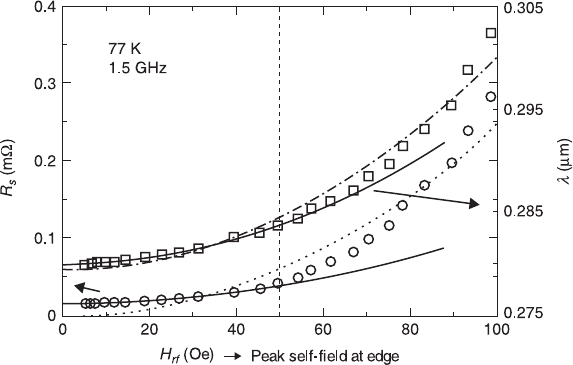
variable amplitude and duration can be investigated. Figure 10.3 shows a
representative example of the microwave magnetic field H
rf
dependence of R
S
and
X
S
. The low field quadratic behaviour is usually attributed to the Ginzburg-Landau
depairing mechanism, in which Cooper pairs are broken by being accelerated beyond
the critical velocity in the microwave electric field. The subsequent faster increase
(~H
4
rf
) is usually dominated by hysteretic vortex penetration into the superconducting
grains (Nguyen et al., 1995). In this special case, the trends of the field dependencies
of R
S
(H
rf
) and X
S
(H
rf
) are correlated. However, there is a wide variety of different
10.3 Typical power dependence of an epitaxial YBa
2
Cu
3
O
7
film
measured with the help of the stripline resonator at f = 1.5 GHz and
77.4 K. The vertical dashed line at 50 Oe marks the approximate place
where R
s
and
λ
deviated noticeably from a quadratic dependence on
H
rf
. The solid lines are the best quadratic fits to the low field region
(< 50 Oe), the dashed lines are the best general quadratic fits to the
entire field range to demonstrate the nonquadratic behaviour of R
s
and
λ
, see Nguyen et al. (1995).
Microwave filters using high-temperature superconductors 395
1
2
3
4
5
6
7
8
9
10
1
2
3
4
5
6
7
8
9
20
1
2
3
4
5
6
7
8
9
30
1
2
3
4
5
6
7
8
9
40
1
2
43X
© Woodhead Publishing Limited, 2011
power dependencies of R
S
(H
rf
) and X
S
(H
rf
) and, for most cases, the function behaviour
of R
S
(H
rf
) and X
S
(H
rf
) are not correlated. It might be argued that the loss of correlation
could result from the films being made from different substrates, growth techniques
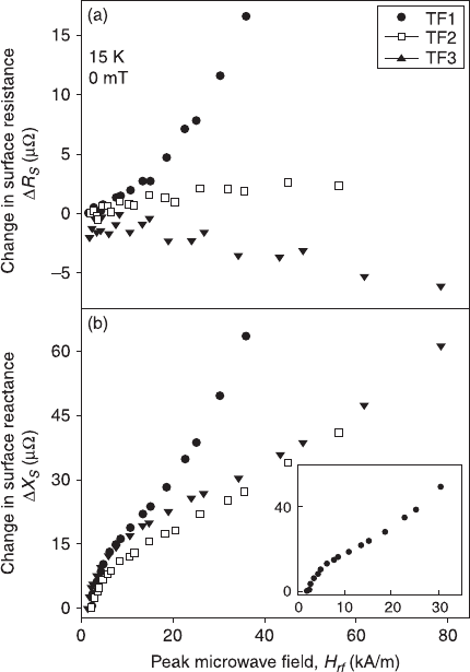
or/and heat treatments. An interesting result from Kharel et al. (1999) may give us a
clue as to how to clarify some of the confusing results mentioned above. They
showed three epitaxial co-evaporated YBCO films on MgO substrates at different
temperatures, which demonstrated a great variety of behaviours, including decreasing,
independent and increasing functions of R
S
(H
rf
), despite the function form of X
S
(H
rf
)
being very similar for all the three films (Fig. 10.4). From Equations 10.5 and 10.6 it
can be seen that R
S
∝
σ
1
∝ n
n
τ
, where
τ
is the quasiparticle scattering time, and X
S
∝
λ
∝ √n
S
. Since X
S
(H
rf
) does not vary from film to film, this strongly suggests that
there should be no profound changes in n
s
from sample to sample, and hence no such
10.4 The change in R
s
and X
s
for three epitaxial YBa
2
Cu
3
O
7
films
on MgO substrates as a function of peak microwave field H
rf
dependencies. The measurements are made by using the coplanar
resonator technique at 8 GHz and 15 K. The inset shows data for
sample TF1 on an expanded scale, see Kharel et al. (1999).
396 High-temperature superconductors
1
2
3
4
5
6
7
8
9
10
1
2
3
4
5
6
7
8
9
20
1
2
3
4
5
6
7
8
9
30
1
2
3
4
5
6
7
8
9
40
1
2
43X
© Woodhead Publishing Limited, 2011
change in n
n
(since the total number of electrons is a constant). Therefore the
remarkable change of R
S
(H
rf
) most likely originates from the power-dependent
quiasiparticle conductivity
σ
1
or, more precisely, from the power-dependent
τ
, the
enhanced quasiparticle scattering due to defects and impurities. Those extrinsic
mechanisms probably co-exist with intrinsic ones (such as Ginzburg-Landau
depairing) and, acting together, lead to the uncorrelated behaviour.
Apart from the direct measurement of nonlinearity by studying the microwave
power (H
2
rf
) dependence of surface impedance, harmonic generation (HG) and
intermodulation distortion products (IMD), measurements provide a more sensitive
probe of nonlinearity at extremely low power levels, where the device response
otherwise appears linear. According to the classical theory of IMD in nonlinear
systems, with the impedance being proportional to H
2
rf
, IMD products generally
scale with the third power of the input power. This is usually referred to as 3:1
scaling. In IMD measurements, two microwave signals at frequencies f
1
and f
2
,
with a frequency separation of ∆
f being much less than f
1
or f
2
, are placed
symmetrically around the resonant frequency. The two microwave signals are
combined using a power combiner and passed through a variable attenuator to the
resonator loaded with film. These nonlinear effects are often expressed by a single
parameter called the ‘third order intercept’, TOI, which is the intercept point of the
two input-output power lines for the fundamental and the third harmonic in a log-
log scale. The typical 3:1 behaviour of a three-pole YBCO band-pass filter with a
mid-band frequency of 9.5 GHz is demonstrated by Yoshitake and Tahara (1995),
where the upper line is the fundamental mode and the lower two lines are the third-
order distortion products, measured at 55 and 77 K, respectively. However
deviations from 3:1 are often reported from the literature. After considering a great
variety of power dependencies of Zs (H
rf
), Velichko et al. (2005) found that, from
a theoretical point of view, the lower power slope must always be 3:1, independently
of the functional form of Zs(H
rf
). But, at intermediate powers, IMD slopes may
indeed vary significantly and can often be less than three. Therefore, Velichko
suggested that the deviation from the 3:1 scaling frequently observed in IMD
measurements of HTS films has a purely technical origin, and proposed that the
spectral characteristics of microwave sources do not always allow the researchers
to use low enough powers to observe the 3:1 scaling. Instead, the measurements
are often possible only above a certain microwave power (set by the resolution of
the detection system), in which the slope is lower than 3:1.
10.3 Superconducting transmission lines and related
passive devices
10.3.1 Superconducting transmission lines
In microwave circuits, a transmission line is the material medium (or structure)
that forms all or part of a path for directing the transmission of electromagnetic
Microwave filters using high-temperature superconductors 397
1
2
3
4
5
6
7
8
9
10
1
2
3
4
5
6
7
8
9
20
1
2
3
4
5
6
7
8
9
30
1
2
3
4
5
6
7
8
9
40
1
2
43X
© Woodhead Publishing Limited, 2011
waves from one place to another. It not only serves as an interconnection between
the components in the circuits, but also often forms the basic element of
components and devices. It is indeed the foundation of microwave circuits, and
most microwave theories have originated directly or indirectly from transmission
theory, something which is also true for superconducting devices.
The most important effect of superconducting transmission lines is their very
low loss. A superconducting transmission line is dispersionless, provided the
wave propagated is in a TEM mode. This is due to the fact that the penetration
depth does not vary with frequency, a contrast with normal conductors, where
skin depth is a function of frequency.
The realistic transmission line model represents the transmission line as an infinite
series of two-port elementary components, each representing an infinitesimally short
segment of the transmission line with distributed resistance R, inductance L, and
capacitance C. Transmission lines which are commonly used include wires, coaxial
cables, dielectric slabs, optical fibres, electric power lines, waveguides, and planar
transmission lines, etc. Considering that most superconducting filters are based on
superconducting films, in this chapter we will concentrate on the planar transmission
lines, i.e., microstrip, coplanar, and stripline.
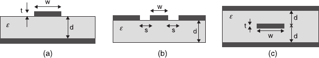
Microstrip is a widely used type of microwave transmission line, which consists
of a conducting strip (with a width w and a thickness t) separated from a ground
plane by a dielectric layer known as the substrate (with a dielectric constant
ε
and a thickness d). The general structure of a microstrip is shown schematically in
Fig. 10.5(a). The fields in the microstrip extend within two media: air above and
dielectric below. In general, the dielectric constant of the substrate will be greater
than that of the air, so the wave is travelling in an inhomogeneous medium. In
consequence, the propagation velocity is somewhere between the speed of
microwaves in the substrate and the speed of microwaves in air. This behaviour is
commonly described by stating the effective dielectric constant (or effective
relative permittivity) of the microstrip, this being the dielectric constant of an
equivalent homogeneous medium. Due to its inhomogeneous nature, the
microstrip line will not support a pure TEM wave; both the E and H fields will
have longitudinal components. However, the longitudinal components are small,
so the dominant mode is referred to as quasi-TEM. The field propagation
velocities will depend not only on the properties of the material, but also on the
physical dimensions of the microstrip. Compared to other transmission lines, such
as traditional waveguide technology, the advantage of a microstrip is that it is
much less expensive, as well as being far lighter and more compact. On the other
hand, the disadvantages of a microstrip compared to a waveguide are its generally
lower power handling capacity, and higher losses, of which the latter can be
greatly improved through the use of superconducting materials.
A coplanar line is formed from a conductor separated from a pair of ground
planes, all on the same plane, at the top of a dielectric medium (Fig. 10.5(b)). In
an ideal case, the thickness of the dielectric is infinite; in practice, it should be
398 High-temperature superconductors
1
2
3
4
5
6
7
8
9
10
1
2
3
4
5
6
7
8
9
20
1
2
3
4
5
6
7
8
9
30
1
2
3
4
5
6
7
8
9
40
1
2
43X
© Woodhead Publishing Limited, 2011
thick enough so that EM fields die out before they leave the substrate. The
advantages of a coplanar line are that active devices can be mounted on top of the
circuit, as on a microstrip. More importantly, it can provide an extremely high
frequency response (100 GHz or more) since connecting to a coplanar line does
not entail any parasitic discontinuities in the ground plane. This means that only
single-side superconducting film is required for a superconducting coplanar line,
which greatly reduces the difficulties in film making since double-sided films
need special technology, especially for those newly discovered superconductors.
One of the disadvantages of the coplanar line is the imbalance in its ground planes,
although they are connected together at some points in the circuit. The potential
of the ground planes can become different on each side, which may produce
unwanted modes and interference. The problem can be solved to some extent by
connecting the two ground planes somewhere in the circuit with a ‘flying wire’
(air bridge) over the conducting plane. However, it will create other problems,
such as greater complexity.
A standard stripline uses a flat strip of metal, which is sandwiched between two
parallel ground planes (Fig. 10.5(c)). The width of the strip, the thickness of the
substrate (the insulating material between the two ground plans) and the relative
permittivity of the substrate determine the characteristic impedance of the
transmission line. The advantage of the stripline is that radiation losses are
eliminated and a pure TEM mode can be propagated within it. The disadvantage
of the stripline is the difficulty in constructing it, especially in superconducting
films. It requires two pieces of superconducting films, both double-sided, or one
single- plus one double-sided film. The air gap, though extremely small, will
cause perturbations in impedance as well as making it very difficult to form
contacts with external circuits. Besides, if two pieces of double-sided films are
used, the need for precise aiming between the very fine patterns of two films
creates another problem.
10.3.2 Application of transmission lines 1:
superconducting delay line
A delay line consists of a long transmission line, which is used to delay incoming
signals for a given amount of time, while minimizing the distortion caused by
10.5 Cross-section geometries of microstrip (a), coplanar line (b), and
stripline (c).

Microwave filters using high-temperature superconductors 399
1
2
3
4
5
6
7
8
9
10
1
2
3
4
5
6
7
8
9
20
1
2
3
4
5
6
7
8
9
30
1
2
3
4
5
6
7
8
9
40
1
2
43X
© Woodhead Publishing Limited, 2011
crosstalk, dispersion and loss. Conventional delay lines, such as coaxial cables
and printed circuit delay lines, present the problems of large volume and
unacceptable insertion loss. Superconducting delay lines with extremely small
losses and compact sizes offer a promising solution for these problems.
All of the three types of superconducting transmission lines mentioned above
can be used for making delay lines. However, the advantages of coplanar lines are
distinctive. First, the ground planes in between the signal line provide a shield,
which reduces the crosstalk. Secondly, the line width of the signal line is quite
flexible since the impedance of the coplanar line is mainly determined by the ratio
between the signal line width and the gap width. The disadvantage is that the
unwanted odd mode can be excited by turnings, curvatures, or any asymmetry
with respect to the signal line, which can be resolved by bonding crossover ‘flying
wires’ (air bridges) between the ground planes over the top of the signal line.
Stripline is the only planar transmission line without modal dispersion. It has a
longer delay per unit length, since the signal propagation velocity is slower than
that of the other two lines. It also has less cross talk than the microstrip line due to
the existence of the top plane. An excellent example of the application of striplines
can be found in the work reported by Lyons et al. (1996), where the delay line was
used for a chirp-response tapped filter. They used a pair of YBCO striplines to
form a double spiral configuration and the chirp function was achieved by a series
of
λ
/4 backward-wave couplers to realize the requested frequency dependent
delay for different frequency components in the signal. This chirp filter was
installed in a 3 GHz band width spectral analysis receiver.
10.3.3 Application of transmission lines 2:
superconducting resonator
A microwave resonator is a simple structure, which can be made of cavity or
transmission line, and is able to contain at least one oscillating electromagnetic
field. If an oscillating field is set up within a resonator, it will gradually decay
because of losses. By using superconductors, the losses can be greatly reduced
and high Q-values can then be achieved. Resonators are the most fundamental
building blocks in the majority of microwave circuits. By coupling a number of
resonators together, a microwave filter can be constructed. A high Q-resonator
forms the main feedback element in a microwave oscillator. The quality factor for
a resonator is defined by
[10.7]
where w is the energy stored in the resonator, and p is the dissipated energy per
period in the resonator.
Losses in a resonator occur due to a number of mechanisms. The most important
are usually the losses associated with conduction currents in the conducting layer
400 High-temperature superconductors
1
2
3
4
5
6
7
8
9
10
1
2
3
4
5
6
7
8
9
20
1
2
3
4
5
6
7
8
9
30
1
2
3
4
5
6
7
8
9
40
1
2
43X
© Woodhead Publishing Limited, 2011
of the cavity or transmission line, the finite loss tangent of the dielectric substrate,
and radiation loss from the open aperture. The total quality factor can be found by
adding these losses together, resulting in
[10.8]
where Q
c
, Q
d
, and Q
r
are the conductor, dielectric and radiation quality factors,
respectively. For conventional cavity or transmission line resonators at microwave
frequency, Q
c
usually dominates. This is why a superconductor can greatly
increase the Q-value of the resonators.
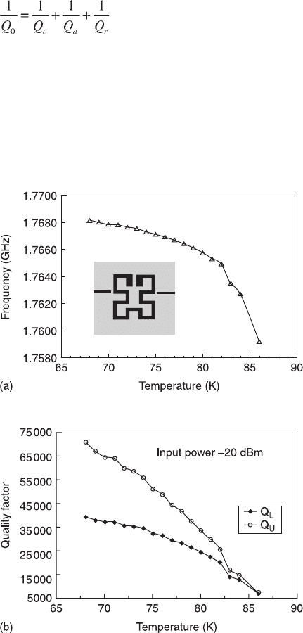
For superconducting resonators, the resonant frequency and the Q-values (both
loaded Q
L
and unloaded Q
U
values) are temperature dependent, and the variation
is remarkable when close to T
c
, as shown in Fig. 10.6 (Li et al., 2002). It is
10.6 Temperature dependence of resonate frequency (a) and Q-values
(b) of superconducting resonator, see Li et al. (2002).
Microwave filters using high-temperature superconductors 401
1
2
3
4
5
6
7
8
9
10
1
2
3
4
5
6
7
8
9
20
1
2
3
4
5
6
7
8
9
30
1
2
3
4
5
6
7
8
9
40
1
2
43X
© Woodhead Publishing Limited, 2011
therefore preferable to operate at a temperature below 80% of T
c
, where a more
stable resonant frequency and a high enough Q-value can be achieved.
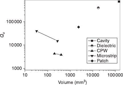
Aside from the Q-value, size is also important in an HTS resonator, not only in
terms of the commercial consideration of reducing the cost, but also because the
HTS filters need to work at low temperatures and their large size will increase the
burden on the cryo-cooler. However, high quality factor and minimal size are
often a contradictory pair because a reduction in size always results in a reduction
in the stored energy, and hence the Q-values. The quality factors and volumes of
various kinds of HTS resonators are shown in Fig. 10.7 in dual-log coordinate at
frequency around 5 GHz. All the data come from literature published over the last
decades. Here, the volume of the planar resonators is calculated by assuming it
has a height of 8 mm.
HTS cavity resonators are usually designed to resonate in the TE
011
mode. In
this mode, the current flow is circumferential, so there is no current flow across
the join of the side wall and the end plates. Although such structures have very
high Q-values, their volume becomes prohibitively large at low frequencies. HTS
dielectric resonators usually consist of a dielectric rod of single crystal material,
which is sandwiched between two planar HTS films. They can have very high
Q-values (if very large area high quality superconducting films are applied), but
are smaller than unloaded resonant cavities. Due to their large volume and
difficulty in realizing cross couplings, HTS cavity resonators and HTS dielectric
resonators are often used to construct low-phase noise oscillators and, in the case
of the dielectric ones, to measure the surface resistance of HTS thin films. They
are seldom used in HTS filters. Patch resonators, which are two dimensional
resonators, are of interest in the design of high power handling HTS filters. An
associated advantage of these resonators is their lower conductor losses compared
with one dimensional line resonators. However, patch resonators tend to have
stronger radiation, so they are not suitable for designing narrow band filters. The
10.7 The quality factor vs. volume of different kinds of HTS resonators.