Short T.A. Electric Power Distribution Handbook
Подождите немного. Документ загружается.


Transformers
165
overhead transformer is the 25-kVA unit; padmounted transformers tend to
be slightly larger where the 50-kVA unit is the most common.
Distribution transformer impedances are rather low. Units under 50 kVA
have impedances less than 2%. Three-phase underground transformers in
the range of 750 to 2500 kVA normally have a 5.75% impedance as specified
in (ANSI/IEEE C57.12.24-1988). Lower impedance transformers provide bet-
ter voltage regulation and less voltage flicker for motor starting or other
fluctuating loads. But lower impedance transformers increase fault currents
on the secondary, and secondary faults impact the primary side more (deeper
voltage sags and more fault current on the primary).
Standards specify the insulation capabilities of distribution transformer
windings (see Table 4.3). The low-frequency test is a power-frequency (60
Hz) test applied for one minute. The basic lightning impulse insulation level
(BIL) is a fast impulse transient. The front-of-wave impulse levels are even
shorter-duration impulses.
The through-fault capability of distribution transformers is also given in
IEEE C57.12.00-2000 (see Table 4.4). The duration in seconds of the short-
circuit capability is:
where
I
is the symmetrical current in multiples of the normal base current
from Table 4.4.
Overhead and padmounted transformer tanks are normally made of mild
carbon steel. Corrosion is one of the main concerns, especially for anything
on the ground or in the ground. Padmounted transformers tend to corrode
TABLE 4.3
Insulation Levels for Distribution Transformers
Low-Frequency
Test Level,
kV rms
Basic Lightning
Impulse Insulation Level,
kV Crest
Chopped-Wave Impulse Levels
Minimum Voltage,
kV Crest
Minimum
Time to
Flashover,
m
s
10 30 36 1.0
15 45 54 1.5
19 60 69 1.5
26 75 88 1.6
34 95 110 1.8
40 125 145 2.25
50 150 175 3.0
70 200 230 3.0
95 250 290 3.0
140 350 400 3.0
Source
: IEEE Std. C57.12.00-2000. Copyright 2000 IEEE. All rights reserved.
t
I
=
1250
2
1791_C04.fm Page 165 Thursday, August 7, 2003 11:18 AM
(C) 2004 by CRC Press LLC

166
Electric Power Distribution Handbook
near the base (where moisture and dirt and other debris may collect). Sub-
mersible units, being highly susceptible to corrosion, are often stainless steel.
Distribution transformers are “self cooled”; they do not have extra cooling
capability like power transformers. They only have one kVA rating. Because
they are small and because customer peak loadings are relatively short
duration, overhead and padmounted distribution transformers have signif-
icant overload capability. Utilities regularly size them to have peak loads
exceeding 150% of the nameplate rating.
Transformers in underground vaults are often used in cities, especially for
network transformers (feeding secondary grid networks). In this application,
heat can be effectively dissipated (but not as well as with an overhead or
padmounted transformer).
Subsurface transformers are installed in an enclosure just big enough to
house the transformer with a grate covering the top. A “submersible” trans-
former is normally used, one which can be submerged in water for an
extended period (ANSI/IEEE C57.12.80-1978). Heat is dissipated through
the grate at the top. Dirt and debris in the enclosure can accelerate corrosion.
Debris blocking the grates or vents can overheat the transformer.
Direct-buried transformers have been attempted over the years. The main
problems have been overheating and corrosion. In soils with high electrical
and thermal resistivity, overheating is the main concern. In soils with low
electrical and thermal resistivity, overheating is not as much of a concern,
but corrosion becomes a problem. Thermal conductivity in a direct-buried
transformer depends on the thermal conductivity of the soil. The buried
transformer generates enough heat to dry out the surrounding soil; the dried
soil shrinks and creates air gaps. These air gaps act as insulating layers that
further trap heat in the transformer.
4.3 Single-Phase Transformers
Single-phase transformers supply single-phase service; we can use two or
three single-phase units in a variety of configurations to supply three-phase
TABLE 4.4
Through-Fault Capability of Distribution Transformers
Single-Phase Rating, kVA Three-Phase Rating, kVA
Withstand Capability in per
Unit of Base Current
(Symmetrical)
5–25 15–75 40
37.5–110 112.5–300 35
167–500 500 25
Source
: IEEE Std. C57.12.00-2000,
IEEE Standard General Requirements for Liquid-Immersed Distri-
bution, Power, and Regulating Transformers
.
1791_C04.fm Page 166 Thursday, August 7, 2003 11:18 AM
(C) 2004 by CRC Press LLC
Transformers
167
service. A transformer’s nameplate gives the kVA ratings, the voltage ratings,
percent impedance, polarity, weight, connection diagram, and cooling class.
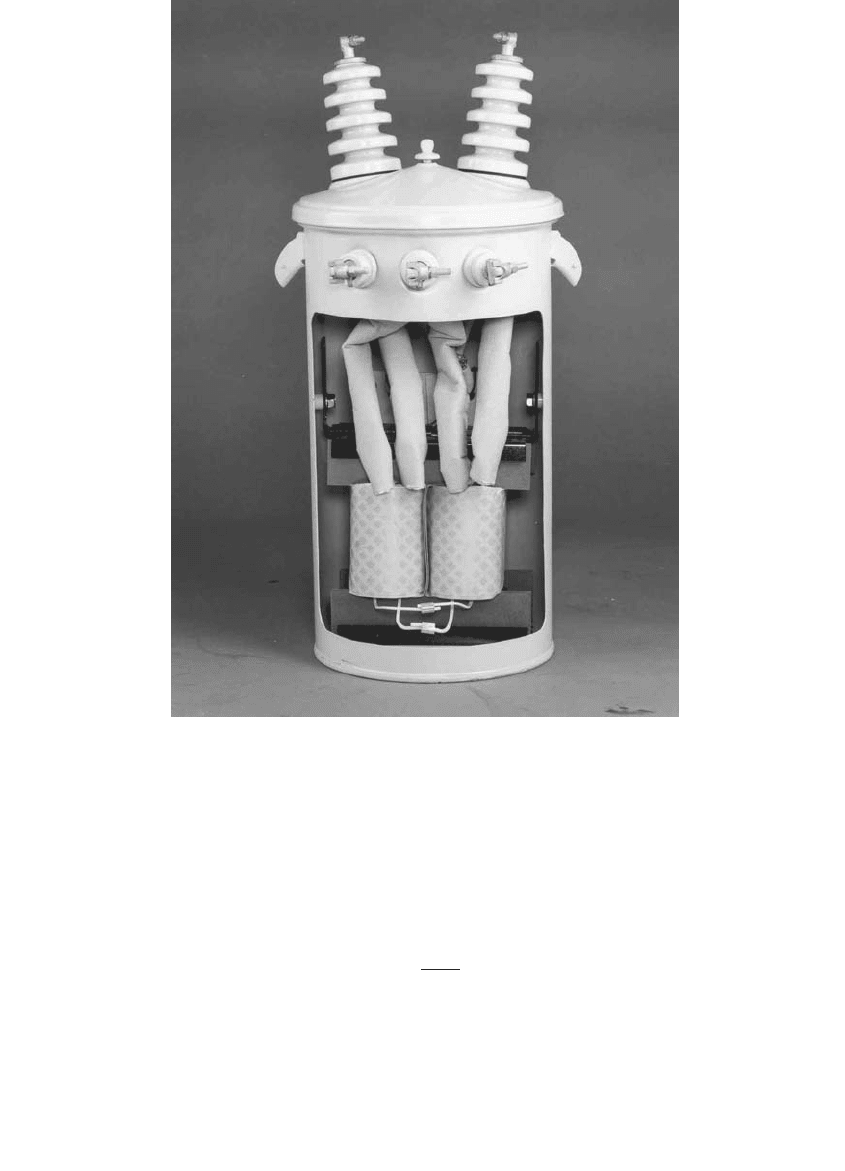
Figure 4.4 shows a cutaway view of a single-phase transformer.
For a single-phase transformer supplying single-phase service, the load-
full current in amperes is
where
S
kVA
= Transformer kVA rating
V
kV
= Line-to-ground voltage rating in kV
FIGURE 4.4
Single-phase distribution transformer. (Photo courtesy of ABB, Inc. With permission.)
I
S
V
kVA
kV
=
1791_C04.fm Page 167 Thursday, August 7, 2003 11:18 AM
(C) 2004 by CRC Press LLC
168
Electric Power Distribution Handbook
So, a single-phase 50-kVA transformer with a high-voltage winding of
12470GrdY/7200 V has a full-load current of 6.94 A on the primary. On a 240/
120-V secondary, the full-load current across the 240-V winding is 208.3 A.
Table 4.5 and Table 4.6 show the standard single-phase winding connec-
tions for primary and secondary windings. High-voltage bushings are
labeled H*, starting with H1 and then H2 and so forth. Similarly, the low-
voltage bushings are labeled X1, X2, X3, and so on.
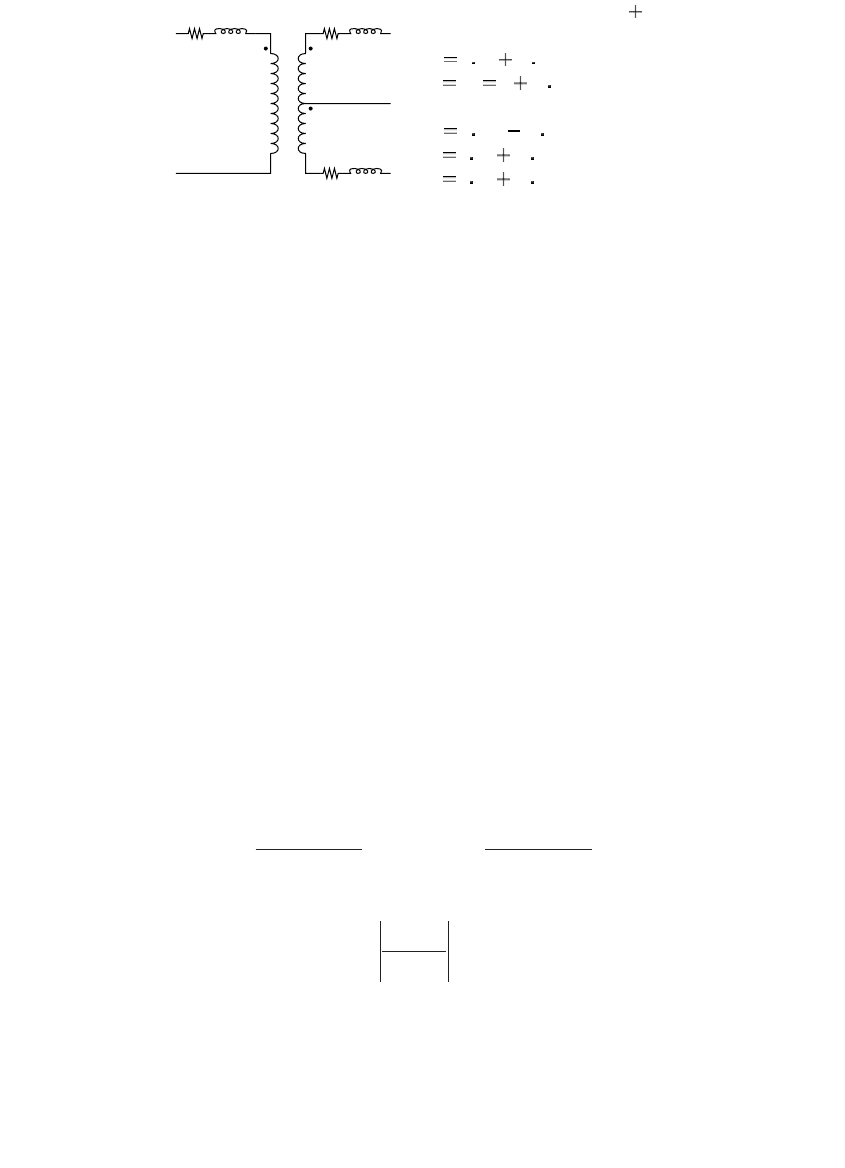
The standard North American single-phase transformer connection is
shown in Figure 4.5. The standard secondary load service is a 120/240-V
three-wire service. This configuration has two secondary windings in series
with the midpoint grounded. The secondary terminals are labeled X1, X2,
and X3 where the voltage X1-X2 and X2-X3 are each 120 V. X1-X3 is 240 V.
Power and distribution transformers are assigned polarity dots according
to the terminal markings. Current entering H1 results in current leaving X1.
The voltage from H1 to H2 is in phase with the voltage from X1 to X3.
On overhead distribution transformers, the high-voltage terminal H1 is
always on the left (when looking into the low-voltage terminals; the termi-
nals are not marked). On the low-voltage side, the terminal locations are
different, depending on size. If X1 is on the right, it is referred to as
additive
polarity
(if X3 is on the right, it is
subtractive polarity
). Polarity is additive if
the voltages add when the two windings are connected in series around the
transformer (see Figure 4.6). Industry standards specify the polarity of a
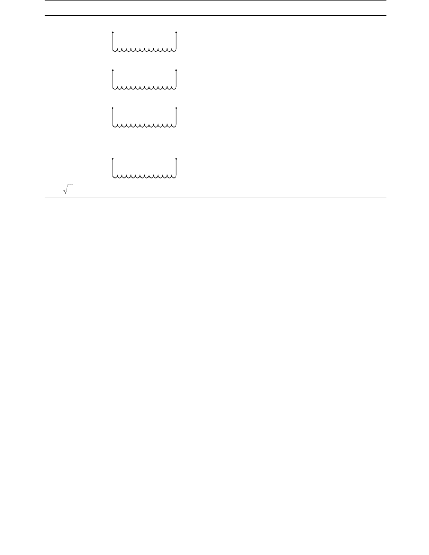
TABLE 4.5
Winding Designations for Single-Phase Primary and Secondary Transformer
Windings with One Winding
Nomenclature Examples Description
E 13800 E shall indicate a winding of E volts that is suitable for
D
connection on an E volt system.
E/E
1
Y 2400/4160Y E/E
1
Y shall indicate a winding of E volts that is suitable
for
D
connection on an E volt system or for Y connection
on an E
1
volt system.
E/E
1
GrdY 7200/12470GrdY E/E
1
GrdY shall indicate a winding of E volts having
reduced insulation that is suitable for
D
connection on
an E volt system or Y connection on an E
1
volt system,
transformer, neutral effectively grounded.
E
1
GrdY/E 12470GrdY/7200
480GrdY/277
E
1
GrdY/E shall indicate a winding of E volts with
reduced insulation at the neutral end. The neutral end
may be connected directly to the tank for Y or for single-
phase operation on an E
1
volt system, provided the
neutral end of the winding is effectively grounded.
E
1
= E
Note
:E is line-to-neutral voltage of a Y winding, or line-to-line voltage of a
D
winding.
Source
: IEEE Std. C57.12.00-2000. Copyright 2000 IEEE. All rights reserved.
3
1791_C04.fm Page 168 Thursday, August 7, 2003 11:18 AM
(C) 2004 by CRC Press LLC
Transformers 169
TABLE 4.6
Two-Winding Transformer Designations for Single-Phase Primaries and Secondaries
Nomenclature Examples Description
E/2E 120/240
240/280
E/2E shall indicate a winding, the sections of which
can be connected in parallel for operation at E
volts, or which can be connected in series for
operation at 2E volts, or connected in series with
a center terminal for three-wire operation at 2E
volts between the extreme terminals and E volts
between the center terminal and each of the
extreme terminals.
2E/E 240/120 2E/E shall indicate a winding for 2E volts, two-wire
full kilovoltamperes between extreme terminals,
or for 2E/E volts three-wire service with 1/2 kVA
available only, from midpoint to each extreme
terminal.
E ¥ 2E 240 ¥ 480 E ¥ 2E shall indicate a winding for parallel or series
operation only but not suitable for three-wire
service.
Source: IEEE Std. C57.12.00-2000. Copyright 2000 IEEE. All rights reserved.
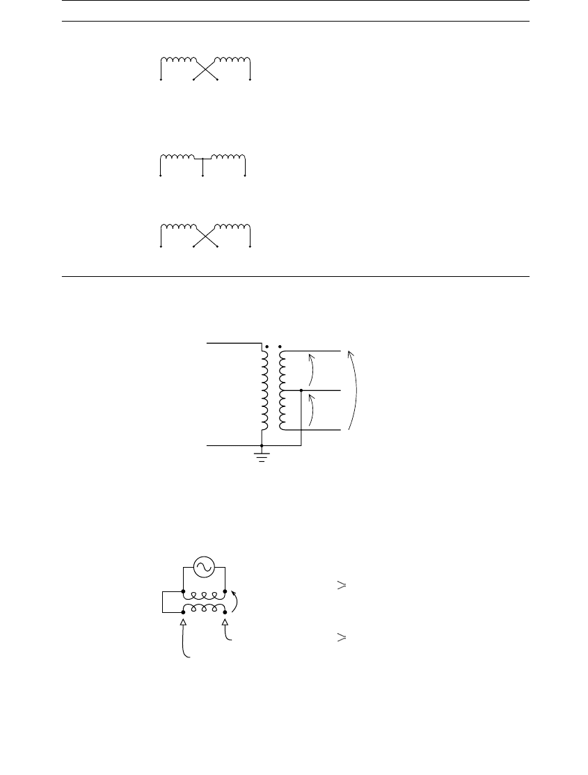
FIGURE 4.5
Single-phase distribution transformer diagram.
FIGURE 4.6
Additive and subtractive polarity.
X1X2X3X4
X1X2X3
X1X2X3X4
120 V
120 V
240 V
X1
X3
X2
H1
H1
Additive:
H2
X1 if additive
X1 if subtractive
Subtractive:
(>200kVA or >8660V)
V
1
V
2
V
2
V
1
V
1
V
2
1791_C04.fm Page 169 Thursday, August 7, 2003 11:18 AM
(C) 2004 by CRC Press LLC

170 Electric Power Distribution Handbook
transformer, which depends on the size and the high-voltage winding. Sin-
gle-phase transformers have additive polarity if (IEEE C57.12.00-2000):
kVA £ 200 and V £ 8660
All other distribution transformers have subtractive polarity. The reason
for the division is that originally all distribution transformers had additive
polarity and all power transformers had subtractive polarity. Increasing sizes
of distribution transformers caused overlap between “distribution” and
“power” transformers, so larger distribution transformers were made with
subtractive polarity for consistency. Polarity is important when connecting
single-phase units in three-phase banks and for paralleling units.
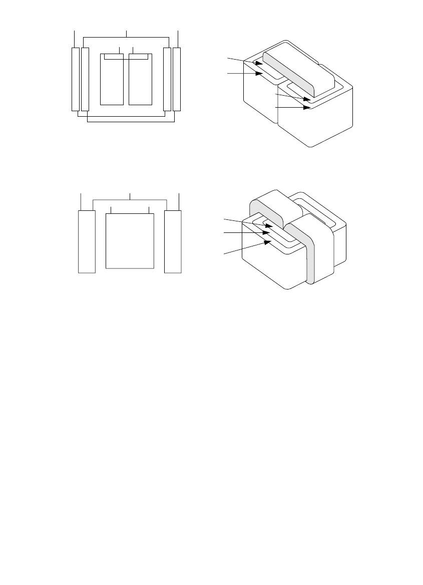
Manufacturers make single-phase transformers as either shell form or core
form (see Figure 4.7). Core-form designs prevailed prior to the 1960s; now,
both shell- and core-form designs are available. Single-phase core-form
transformers must have interlaced secondary windings (the low-high-low
design). Every secondary leg has two coils, one wrapped around each leg
of the core. The balanced configuration of the interlaced design allows
unbalanced loadings on each secondary leg. Without interlacing, unbal-
anced secondary loads excessively heat the tank. An unbalanced secondary
load creates an unbalanced flux in the iron core. The core-form construction
does not have a return path for the unbalanced flux, so the flux returns
outside of the iron core (in contrast, the shell-form construction has a return
path for such flux). Some of the stray flux loops through the transformer
tank and heats the tank.
The shell-form design does not need to have interlaced windings, so the
noninterlaced configuration is normally used on shell-form transformers since
it is simpler. The noninterlaced secondary has two to four times the reactance:
the secondary windings are separated by the high-voltage winding and the
insulation between them. Interlacing reduces the reactance since the low-
voltage windings are right next to each other.
Using a transformer’s impedance magnitude and load losses, we can find
the real and reactive impedance in percent as
where
S
kVA
= transformer rating, kVA
W
CU
= W
TOT
– W
NL
= load loss at rated load, W
W
TOT
= total losses at rated load, W
W
NL
= no-load losses, W
Z = nameplate impedance magnitude, %
R
W
S
CU
kVA
=
10
XZR=-
22
1791_C04.fm Page 170 Thursday, August 7, 2003 11:18 AM
(C) 2004 by CRC Press LLC
Transformers 171
The nameplate impedance of a single-phase transformer is the full-winding
impedance, the impedance seen from the primary when the full secondary
winding is shorted from X1 to X3. Other impedances are also important; we
need the two half-winding impedances for secondary short-circuit calcula-
tions and for unbalance calculations on the secondary. One impedance is the
impedance seen from the primary for a short circuit from X1 to X2. Another
is from X2 to X3. The half-winding impedances are not provided on the
nameplate; we can measure them or use the following approximations. Fig-
ure 4.8 shows a model of a secondary winding for use in calculations.
The half-winding impedance of a transformer depends on the construction.
In the model in Figure 4.8, one of the half-winding impedances in percent
equals Z
A
+ Z
1
; the other equals Z
A
+ Z
2
. A core- or shell-form transformer
with an interlaced secondary winding has an impedance in percent of
approximately:
Z
HX1–2
= Z
HX2–3
= 1.5 R + j 1.2 X
FIGURE 4.7
Core-form and shell-form single-phase distribution transformers. (From IEEE Task Force Report,
“Secondary (Low-Side) Surges in Distribution Transformers,” IEEE Trans. Power Delivery, 7(2),
746–756, April 1992. With permission. ©1992 IEEE.)
H1 H2
X2
Core
ILV
HV
OLV
Coils
ILV
OLV
HV
X1
X3
H1 H2
Shell form, non-interlaced
Core
Coils
Core form, interlaced
LV
HV
LV
HV
X2
X1
X3
HV
HV
ILV1
ILV2
OLV1
OLV2
1791_C04.fm Page 171 Thursday, August 7, 2003 11:18 AM
(C) 2004 by CRC Press LLC
172 Electric Power Distribution Handbook
where R and X are the real and reactive components of the full-winding
impedance (H1 to H2 and X1 to X3) in percent. A noninterlaced shell-form
transformer
has an impedance in percent of approximately:
Z
HX1–2
= Z
HX2–3
= 1.75 R + j 2.5 X
In a noninterlaced transformer, the two half-winding impedances are not
identical; the impedance to the inner low-voltage winding is less than the
impedance to the outer winding (the radius to the gap between the outer
secondary winding and the primary winding is larger, so the gap between
windings has more area).
A secondary fault across one 120-V winding at the terminals of a nonin-
terlaced transformer has current about equal to the current for a fault across
the 240-V winding. On an interlaced transformer, the lower relative imped-
ance causes higher currents for the 120-V fault.
Consider a 50-kVA transformer with Z = 2%, 655 W of total losses, no-load
losses of 106 W, and a noninterlaced 120/240-V secondary winding. This
translates into a full-winding percent impedance of 1.1 + j1.67. For a fault
across the 240-V winding, the current is found as
For a fault across the 120-V winding on this noninterlaced transformer, the
current is found as
FIGURE 4.8
Model of a 120/240-V secondary winding with all impedances in percent. (Impedance data
from [Hopkinson, 1976].)
Z
A
Z
1
Z
2
Full-winding impedance = R jX
Interlaced secondary winding
Z
A
0 5R j0 8X
Z
1
Z
2
R j0 4X
Noninterlaced secondary winding
Z
A
0 25R j0 6X
Z
1
1 5R j3 3X
Z
2
1 5R j3 1X (inner winding)
ZRjX
S
jj
kVA
W
W
,
.
..
.
..
240
22
10 0 24
11 167
10 0 24
50
0 013 0 019
V
kV kV
kVA
=+
()
()
=+
()
()
=+
I
Z
240
240
024
10 4
V
V
kV
kA==
.
.
,W
1791_C04.fm Page 172 Thursday, August 7, 2003 11:18 AM
(C) 2004 by CRC Press LLC

Transformers 173
Consider the same transformer characteristics on a transformer with an
interlaced secondary and Z = 1.4%. The 240-V and 120-V short-circuit cur-
rents are found as
The fault current for a 120-V fault is significantly higher than the 240-V
current.
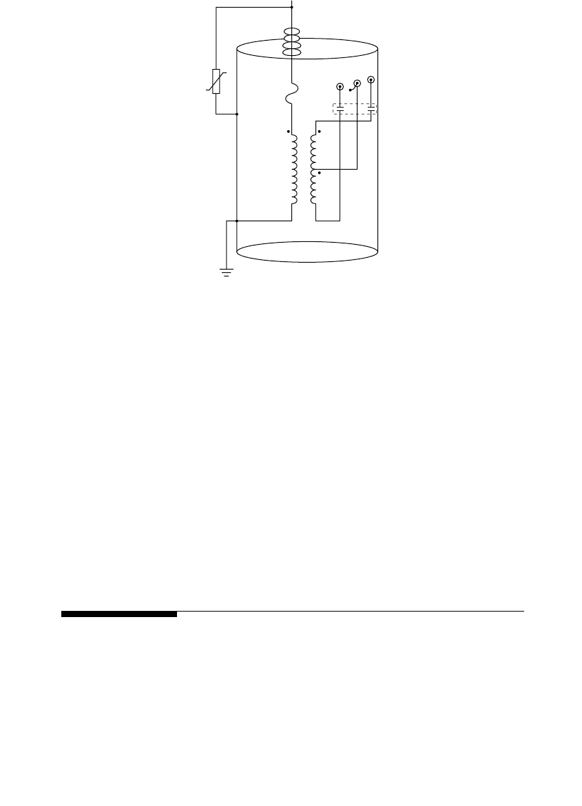
Completely self-protected transformers (CSPs) are a widely used single-
phase distribution transformer with several built-in features (see Figure 4.9):
•Tank-mounted arrester
• Internal “weak-link” fuse
• Secondary breaker
CSPs do not need a primary-side cutout with a fuse. The internal primary
fuse protects against an internal failure in the transformer. The weak link
has less fault-clearing capability than a fuse in a cutout, so they need external
current-limiting fuses where fault currents are high.
ZRjX
S
j
j
kVA
W
W
,
..
.
..
.
..
120
22
175 25
10 0 12
193 418
10 0 12
50
0 0055 0 0120
V
kV kV
kVA
=+
()
()
=+
()
()
=+
I
Z
120
120
012
906
V
V
kV
kA==
.
.
,W
ZRjX
S
jj
kVA
W
W
,
.
..
.
..
240
22
10 0 24
11 087
10 0 24
50
0 013 0 01
V
kV kV
kVA
=+
()
()
=+
()
()
=+
I
Z
240
240
024
14 9
V
V
kV
kA==
.
.
,W
ZRjX
S
j
j
kVA
W
W
,
..
.
..
.
..
120
22
15 12
10 0 12
165 104
10 0 12
50
0 0048 0 003
V
kV kV
kVA
=+
()
()
=+
()
()
=+
I
Z
120
120
012
21 4
V
V
kV
kA==
.
.
,W
1791_C04.fm Page 173 Thursday, August 7, 2003 11:18 AM
(C) 2004 by CRC Press LLC
174 Electric Power Distribution Handbook
Secondary breakers provide protection against overloads and secondary
faults. The breaker responds to current and oil temperature. Tripping is
controlled by deflection of bimetallic elements in series. The oil temperature
and current through the bimetallic strips heat the bimetal. Past a critical
temperature, the bimetallic strips deflect enough to operate the breaker.
Figure 4.10 shows trip characteristics for secondary breakers inside two size
transformers. The secondary breaker has an emergency position to allow
extra overload without tripping (to allow crews time to replace the unit).
Crews can also use the breaker to drop the secondary load.
Some CSPs have overload-indicating lights that signal an overload. The
indicator light doesn’t go off until line crews reset the breaker. The indicator
lights are not ordered as often (and crews often disable them in the field)
because they generate a fair number of nuisance phone calls from curious/
helpful customers.
4.4 Three-Phase Transformers
Three-phase overhead transformer services are normally constructed from
three single-phase units. Three-phase transformers for underground service
(either padmounted, direct buried, or in a vault or building or manhole) are
normally single units, usually on a three- or five-legged core. Three-phase
distribution transformers are usually core construction (see Figure 4.11), with
FIGURE 4.9
Completely self-protected transformer.
X1
X2
X3
H1
weak
link
fuse
1791_C04.fm Page 174 Thursday, August 7, 2003 11:18 AM
(C) 2004 by CRC Press LLC