Short T.A. Electric Power Distribution Handbook
Подождите немного. Документ загружается.


316
Electric Power Distribution Handbook
Circuit breaker or recloser operations are difficult. If
fuse blowing
is used,
where tap fuses always operate before the circuit breaker or recloser, the
percentage of temporary faults cleared by circuit breakers and reclosers is:
A SCADA system produces these numbers, but if this information is not
available, the percentage can be approximated using circuit breaker count
numbers:
where
n =
total number of circuit breaker (or recloser) operations
r =
number of reclose attempts before lockout (there are
r
+1 circuit
breaker operations during a lockout cycle)
l =
number of lockouts
If
fuse saving
is used, where the circuit breaker operates before lateral fuses,
then it is more difficult to estimate the number of temporary faults. For the
whole circuit (it is not possible to separate the faults on the mains from the
faults on the taps), we can estimate the percentage as follows:
where
s =
number of successful reclose sequences
f =
number of fuses replaced following repair (not including nuisance
fuse operations)
f
2
=
number of fuse operations that are not coincident with circuit breaker
trips
f
2
should be close to zero, since the circuit breaker should operate for all
faults. Assuming
f
2
is zero (which may have to be done, since this is a difficult
number to obtain) implies no nuisance fuse operations without a circuit
breaker operation. It is difficult for an outage data management system to
properly determine the number of temporary faults.
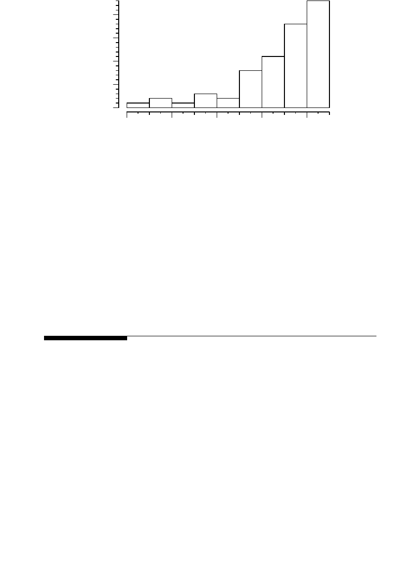
Faults frequently occur near the peak of the voltage waveform as shown
in Figure 7.5. About 60% of the faults in the EPRI fault study occurred when
the voltage was within 5% of the peak prefault voltage (where the angle was
Percent permanent
Number of lockouts
Number of lockouts Number of successful reclose sequences
100%
=
+
¥
Percent permanent =
◊
¥
l
n-r l
%100
Percent permanent =
+
++
¥
lf
lsf
%
2
100
1791_book.fm Page 316 Monday, August 4, 2003 3:20 PM
(C) 2004 by CRC Press LLC
Faults
317
70 to 90
o
). This is reasonable. Any insulation failure, whether it be a squirrel
breaching a bushing or a failure in a cable, more likely strikes with the
voltage at or near its peak. Some faults defy this pattern. Lightning faults
happen at any point on the voltage waveform because the fault occurs when
the lightning strikes (although lightning can cause a flashover but not a fault
if the voltage is very close to a zero-crossing of the power-frequency voltage).
Two-phase and three-phase faults create more instances in which the voltage
is not near its peak.
7.2 Fault Calculations
The magnitude of fault current is limited only by the system impedance and
any fault impedance. The system impedance includes the impedances of
wires, cables, and transformers back to the source. For faults involving
ground, the impedance includes paths through the earth and through the
neutral wire. The impedance of the fault depends on the type of fault.
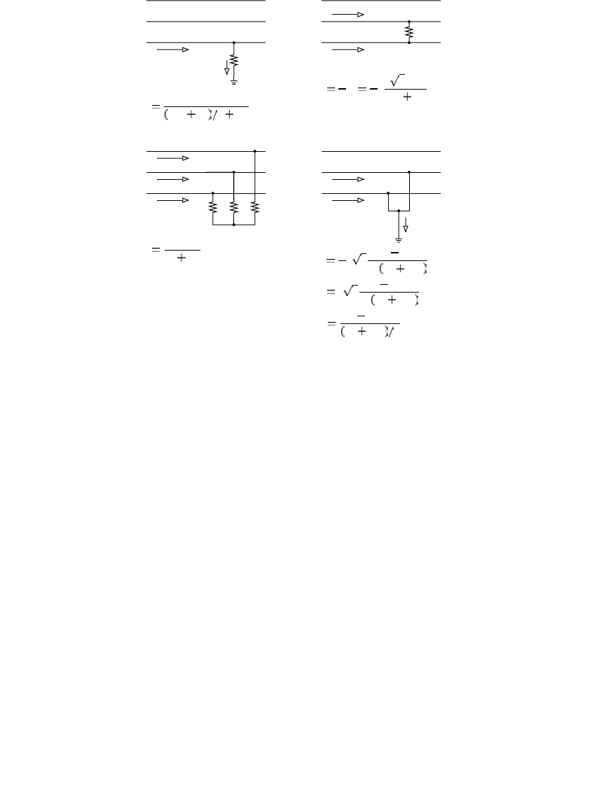
Most distribution primary circuits are radial, with only one source and
one path for fault currents. Figure 7.6 shows equations for calculating fault
currents for common distribution faults.
The equations in Figure 7.6 assume that the positive-sequence impedance
is equal to the negative-sequence impedance. As an example, the impedance
term due to the sequence components for a line-to-line fault is (
Z
1
+ Z
2
),
which simplifies to 2
Z
1
when the impedances are assumed to be equal. This
is accurate for virtually all distribution circuits. With a large generator
nearby, the equivalent circuit may have different positive- and negative-
FIGURE 7.5
Point of fault on the voltage waveform. (Data from [Burke and Lawrence 1984; EPRI 1209-1,
1983].)
Distribution of point on wave at which faults occur, degrees
Percent
020406080
051015 20
020406080
051015 20
1791_book.fm Page 317 Monday, August 4, 2003 3:20 PM
(C) 2004 by CRC Press LLC
318
Electric Power Distribution Handbook
sequence impedances (but that case is usually done on the computer and
not with hand calculations). The maximum currents occur with a bolted fault
where
R
F
is zero. The maximum current for a line-to-line fault is 86.6% of
the maximum three-phase fault current. In all cases, the load current is
ignored. In most cases, load will not significantly change results.
The three-phase fault current is almost always the highest magnitude. On
most circuits, the zero-sequence impedance is significantly higher than the
positive-sequence impedance. One important location where the line-to-
ground fault current may be higher is at the substation. There are two reasons
for this:
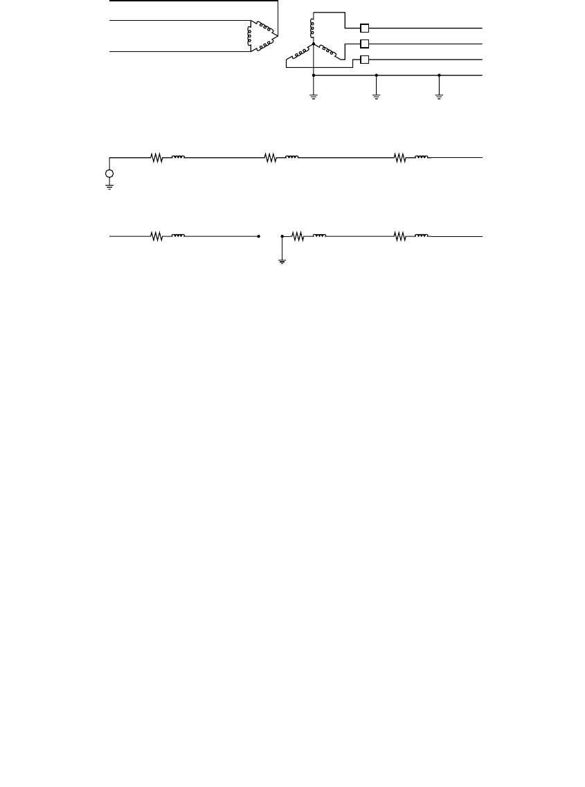
1. A delta – wye transformer is a zero-sequence source. The positive-
sequence impedance includes the impedance of the subtransmission
and transmission system. The zero-sequence impedance does not.
Figure 7.7 shows the sequence diagrams for the positive and zero
sequences. The delta-wye connection forms a zero-sequence source
while the positive-sequence impedance includes the subtransmis-
sion equivalent impedance.
2. If the substation transformer has three-legged core-form construc-
tion, the zero-sequence impedance is lower than its positive-
FIGURE 7.6
Fault-current calculations.
A
B
C
Line-to-ground fault
A
B
C
Line-to-line fault
A
B
C
A
B
C
3-phase fault Line-to-line-to-ground fault
I
A
V
LN
2Z
1
Z
0
3 R
F
I
A
I
B
j
3V
LN
2Z
1
R
F
I
A
V
LN
Z
1
R
F
I
A
j 3
Z
0
aZ
1
Z
1
Z
1
2Z
0
V
LN
I
B
j 3
Z
0
a
2
Z
1
Z
1
Z
1
2Z
0
V
LN
I
G
V
LN
Z
1
2Z
0
3
I
A
I
A
I
A
I
A
I
A
I
B
I
B
I
B
I
C
R
F
R
F
R
F
1791_book.fm Page 318 Monday, August 4, 2003 3:20 PM
(C) 2004 by CRC Press LLC
Faults
319
sequence impedance. Typically, the zero-sequence impedance is 85%
of the positive-sequence impedance, which increases ground-fault
currents by 5.2%.
In cases where the zero-sequence impedance is less than the positive-
sequence impedance, the line-to-ground fault gives the highest phase cur-
rent. The double line-to-ground fault produces the highest-magnitude
ground current.
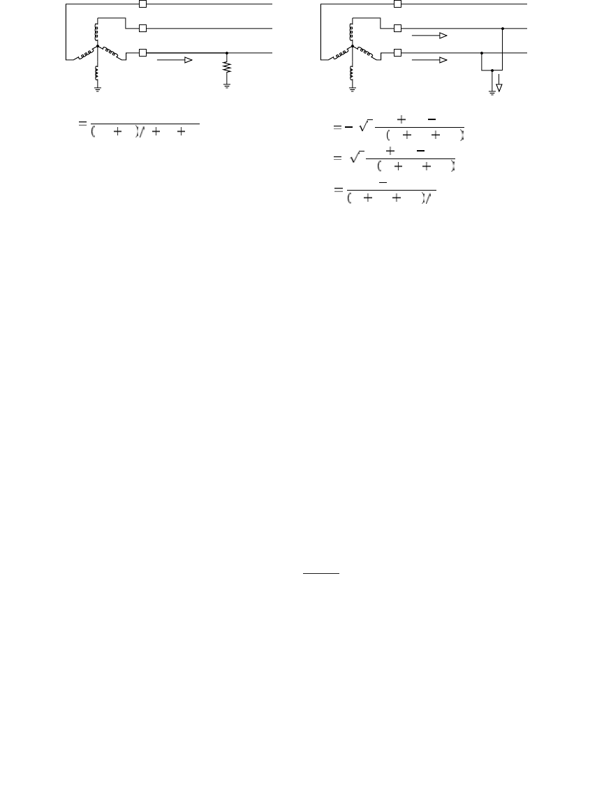
In order to reduce fault currents for line-to-ground faults, a neutral reactor
on the station transformer is sometimes used. Figure 7.8 shows the equations
for faults involving ground for circuits with a neutral reactor (the line-to-
line fault and the three-phase fault are not affected). A common value for a
neutral reactor is 1
W
for 15-kV class distribution circuits.
The impedance seen by line-to-ground faults is a function of both the
positive and the zero sequence impedances. This important loop impedance
is
Z
S
= (2Z
1
+Z
0
)/3. The sequence impedances,
Z
1
and
Z
0
, used in the fault
calculations include the sum of the impedances with both resistance and
reactance along the fault current path. Some of the common branch imped-
ances are given below including some rule-of-thumb values that are useful
for hand calculations:
• Overhead lines:
•|
Z
1
| = 0.5
W
/mi (0.3
W
/km)
•|
Z
S
| = 1
W
/mi (0.6
W
/km)
FIGURE 7.7
Positive and zero-sequence diagrams for a delta – wye substation transformer.
Positive-sequence diagram
Subtransmission system Distribution system
Z
subtrans
Z
trans
Z
distline
Zero-sequence diagram
Z
subtrans
Z
trans
Z
distline
1791_book.fm Page 319 Monday, August 4, 2003 3:20 PM
(C) 2004 by CRC Press LLC
320
Electric Power Distribution Handbook
• Underground cables:
•|
Z
1
| = 0.6
W
/mi (0.35
W
/km)
•|
Z
S
| = 0.5
W
/mi (0.3
W
/km)
• Substation transformer:
•|
Z
1
| = |
Z
S
| = 1
W
•A typical 15-kV substation transformer impedance is 1
W
, which
corresponds to a bus fault current of 7.2 kA for a 12.47-kV circuit.
• Subtransmission equivalent: often can be ignored
See Smith (1980) for an excellent paper on fault calculations for additional
information. Include impedances for step-down transformer banks, series
reactors, and voltage regulators. Use the rule-of-thumb numbers above for
back-of-the-envelope calculations and as checks for computer modeling.
The simplified equation for a transformer impedance is
where
kV =
line-to-line voltage
MVA =
transformer base rating — open air (OA) rating
Z
%
=
transformer impedance, per unit
We ignore the resistive component since the
X/R
ratio of station transform-
ers is generally greater than 10 and often in the range of 20 to 30. The
transmission/subtransmission equivalent is usually small, and we often
FIGURE 7.8
Fault-current calculations with a neutral reactor on the substation transformer.
A
B
C
A
B
C
Line-to-ground fault Line-to-line-to-ground fault
I
A
V
LN
2Z
1
Z
0
3 R
F
Z
G
I
A
j 3
Z
0
3Z
G
aZ
1
Z
1
Z
1
2Z
0
6Z
G
V
LN
I
B
j 3
Z
0
3Z
G
a
2
Z
1
Z
1
Z
1
2Z
0
6Z
G
V
LN
I
G
V
LN
Z
1
2Z
0
6Z
G
3
I
A
I
A
I
B
I
G
R
F
Z
G
Z
G
ZZ j
kV
MVA
Z
10
2
==
%
1791_book.fm Page 320 Monday, August 4, 2003 3:20 PM
(C) 2004 by CRC Press LLC

Faults
321
ignore it (especially for calculating maximum fault currents). Include the
transmission system impedance for weak subtransmission systems such as
34.5-, 46- or 69-kV circuits, or for very large substations. Find the transmis-
sion equivalent from the per unit impedances (
r
1
,
x
1
,
r
0
, and
x
0
) on a given
MVA base referred to the distribution voltage (Smith, 1980) as
where
MVA
b
=
base MVA at which the r and x impedances are given
kV
s
=
line-to-line voltage in kV on the secondary side of the station
transformer
kV
p
=
line-to-line voltage in kV on the primary
kV
pb
=
base line-to-line voltage on the primary used to calculate
MVA
b
(often equal to
kV
p
)
If the transmission impedances are available as a fault MVA with a power
factor, find the transmission equivalent (Smith, 1980) with
where
MVA =
3-phase short-circuit MVA at the primary terminals of the station
transformer (see Table 7.2 for typical maximum values)
kI
g
=
available ground fault current in kA at the primary terminals of the
station transformer
pf =
power factor in per unit for the available three-phase fault current
pf
g
=
power factor in per unit for the available single-phase fault current
While almost all distribution circuits are radial, there may be other fault
current sources. We ignore these other sources most of the time, but occa-
sionally, we consider motors and generators in fault calculations. Synchro-
nous motors and generators contribute large currents relative to their size.
On a typical 15-kV class distribution circuit, one or two megawatts worth
Zrjx
kV
MVA
kV
kV
Zrjx
kV
MVA
kV
kV
s
b
pb
p
s
b
pb
p
11 1
2
2
00 0
2
2
=+
Ê
Ë
Á
ˆ
¯
˜
=+
Ê
Ë
Á
ˆ
¯
˜
()
()
Z
kV
MVA
pf j pf
kV
kV
Z
kV
kI kV
pf j pf
kV
kV
Z
s
pb
p
s
g
pb
gg
pb
p
1
2
2
2
0
2
2
2
1
1
3
12
=+-
Ê
Ë
Á
ˆ
¯
˜
=
◊
+-
Ê
Ë
Á
ˆ
¯
˜
-
()
()
1791_book.fm Page 321 Monday, August 4, 2003 3:20 PM
(C) 2004 by CRC Press LLC
322 Electric Power Distribution Handbook
of connected synchronous units are needed to significantly affect fault cur-
rents. On weaker circuits, smaller units can impact fault currents. Induction
motors and generators also feed faults. Inverter-based distributed generation
can contribute fault current, but generally much less than synchronous or
induction units. Of course, on feeders that have network load, current
through network transformers backfeeds faults until the network protectors
operate.
7.2.1 Transformer Connections
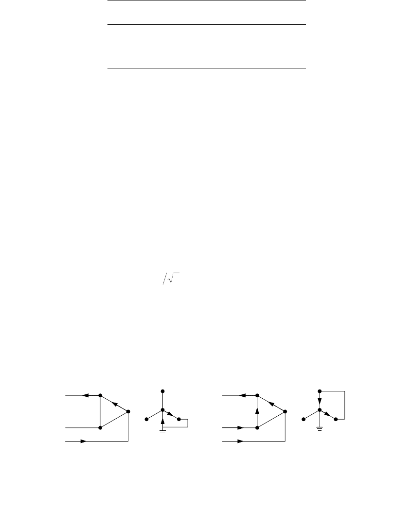
The fault current on each side of a three-phase transformer connection can
differ in magnitude and phasing. In the common case of a delta – grounded-
wye connection, the current on the source side of the transformer differs
from the currents on the fault side for line-to-ground or line-to-line faults
(see Figure 7.9). For a line-to-ground fault on the primary side of the trans-
former, the current appears on two phases on the primary with a per unit
current of 0.577 (which is ).
These differences are often needed when coordinating a primary-side pro-
tective device and a secondary-side device. In distribution substations, this
is commonly a fuse on the primary side and a relay controlling a circuit
breaker on the secondary side. The line-to-line fault must be considered —
this gives more per-unit current on one phase in the primary, 1.15 per unit
TABLE 7.2
Typical Maximum Transmission/Subtransmission
Fault Levels
Transmission Voltage,
kV
Maximum Symmetrical Fault,
MVA
69 3,000
115 5,000
138 6,000
230 10,000
FIGURE 7.9
Per-unit fault-currents on both sides of a delta – grounded-wye transformer.
13
0.577
1
1
0.577
0.577
0.577
1
1
1.15
0.577
0.577
0
0.577
0
Single line-to-ground fault
Line-to-line fault
1791_book.fm Page 322 Monday, August 4, 2003 3:20 PM
(C) 2004 by CRC Press LLC
Faults 323
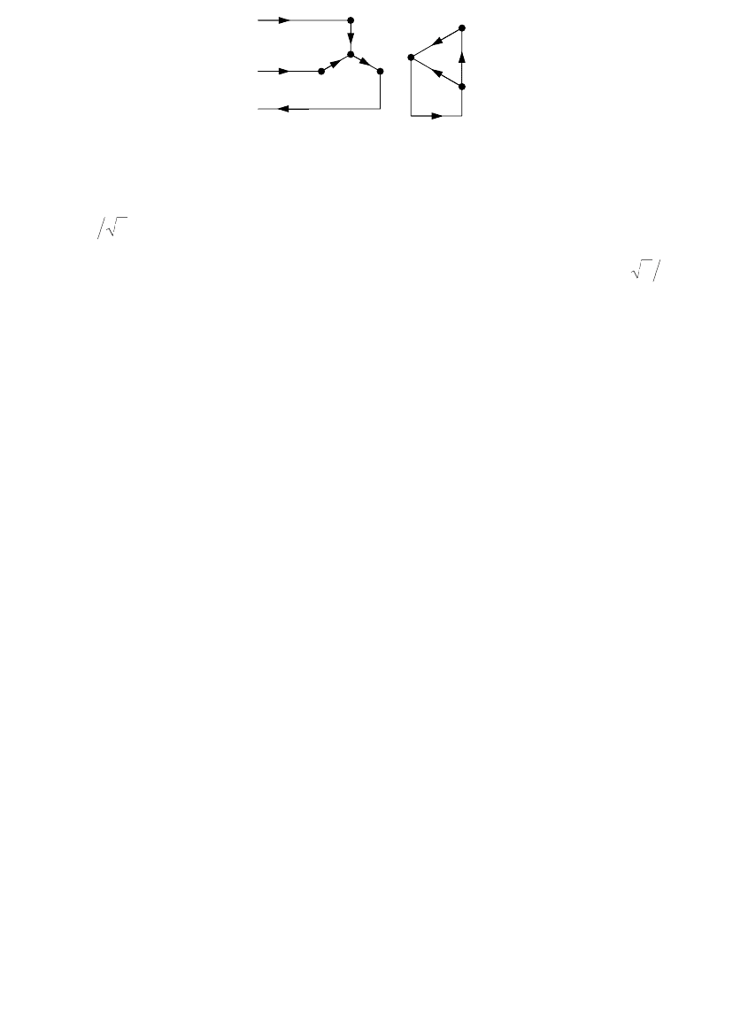
() in one of the phases (see Figure 7.9). To make sure a primary fuse
coordinates with a secondary device, shift the minimum-melting time-cur-
rent curve of the primary-side fuse to the left by a factor of 0.866 =
(after also adjusting for the transformer turns ratio). The current differences
also mean that the transformer is not protected as well for single-phase faults;
a primary-side fuse takes longer to clear the single-phase fault since it sees
less current than for a three-phase or line-to-line fault.
Fault currents are only different for unbalanced secondary currents. For a
three-phase secondary fault, the per-unit currents on the primary equal those
on the secondary (with the actual currents related by the turns ratio of the
transformer). A wye – wye transformer does not disturb the current rela-
tionships; the per-unit currents on both sides of the transformer are equal.
In a floating wye – delta, similar current relationships exist; a line-to-line
secondary fault shows up on the primary side on all three phases, one of
which is 1.15 per unit (see Figure 7.10). For a floating wye – delta transformer
with a larger center-tapped lighting leg and two power legs, fault current
calculations are difficult. Faults can occur from phase to phase and from
phase to the secondary neutral, and the lighting transformer will have a
different impedance than the power leg transformers. For an approach to
modeling this, see Kersting and Phillips (1996).
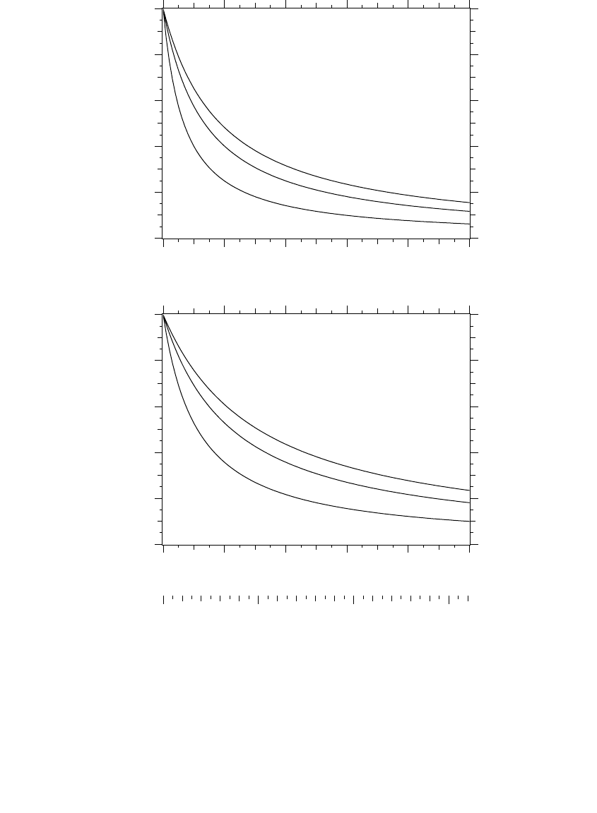
7.2.2 Fault Profiles
Fault profiles show fault current with distance along a circuit. Determining
where thermal or mechanical short-circuit limits on equipment may be
exceeded, helping select or check interrupting capabilities of protective
equipment, and coordinating protective devices are important uses of fault
profiles. Figure 7.11 and Figure 7.12 show typical fault current profiles of
distribution circuits.
Some general trends that the fault profiles show are:
• Distance — The fault current drops off as the inverse of distance (1/d).
• Ground faults — On overhead circuits, the ground fault current
falls off faster (and the ground fault current is generally lower)
FIGURE 7.10
Per-unit fault-currents on both sides of a wye – delta transformer.
1/3
1
1.15
0.577
1/3
2/3
0.577
23
32
1791_book.fm Page 323 Monday, August 4, 2003 3:20 PM
(C) 2004 by CRC Press LLC
324 Electric Power Distribution Handbook
FIGURE 7.11
Fault-current profiles for line-to-ground faults and for three-phase faults for an overhead circuit.
Phase characteristics: 500 kcmil, all-aluminum, GMD = 4.69 ft (1.43 m). Neutral characteristics:
3/0 all-aluminum, 4-ft (1.22-m) line-neutral spacing. Z
1
= 0.207 + j0.628 W/mile (0.1286 + j0.3901
W/km), Z
0
= 0.720 + j1.849 W/mile (0.4475 + j1.1489 W/km), Z
S
= 0.378 + j1.035 W/mile (0.2350
+ j0.6430 W/km).
12.5kV
25kV
34.5kV
0 2 4 6 8 10
0
2
4
6
8
10
12.5kV
25kV
34.5kV
0 2 4 6 8 10
0
2
4
6
8
10
0 5 10 15
Distance from the substation, miles
Ground
fault
current
[kA]
Distance from the substation, miles
3-phase
fault
current
[kA]
km
1791_book.fm Page 324 Monday, August 4, 2003 3:20 PM
(C) 2004 by CRC Press LLC
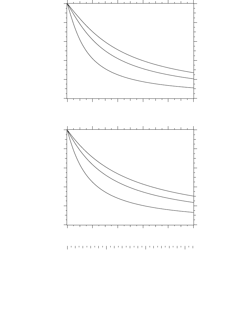
Faults 325
FIGURE 7.12
Fault-current profiles for line-to-ground faults and for three-phase faults for an underground
cable circuit. 500-kcmil aluminum conductor, 220-mil XLPE insulation, 1/3 neutrals, flat spac-
ing, 7.5 in. between cables. Z
1
= 0.3543 + j0.3596 W/mile (0.2201 + j0.2234 W/km), Z
0
= 0.8728
+ j0.2344 W/mile (0.5423 + j0.1456 W/km), Z
S
= 0.5271 + j0.3178 W/mile (0.3275 + j0.1975 W/km).
12.5kV
25kV
34.5kV
0 2 4 6 8 10
0
2
4
6
8
10
12.5kV
25kV
34.5kV
0 2 4 6 8 10
0
2
4
6
8
10
0 5 10 15
Distance from the substation, miles
Ground
fault
current
[kA]
Distance from the substation, miles
3-phase
fault
current
[kA]
km
1791_book.fm Page 325 Monday, August 4, 2003 3:20 PM
(C) 2004 by CRC Press LLC