Short T.A. Electric Power Distribution Handbook
Подождите немного. Документ загружается.


326 Electric Power Distribution Handbook
than the three-phase fault current. The zero-sequence reactance is
generally over three times the positive-sequence reactance, and the
zero-sequence resistance is also higher than the positive-sequence
resistance.
• System voltage — On higher-voltage distribution systems, the fault
current drops off more slowly. The actual line impedance does not
change with voltage (Z
S
ª1 W/mi), and since I = V
LN
/Z, it takes more
impedance (more circuit length) to reduce the fault current.
• Cables — Underground cables have much lower reactance than over-
head circuits, so the fault current does not fall off as fast on under-
ground circuits. Also, note that X/R ratios are lower on cables.
• Profiles — The three-phase and ground-fault profiles of underground
cables are similar. The zero-sequence reactance can actually be
smaller than the positive-sequence reactance (but the zero-sequence
resistance is larger than the positive-sequence resistance).
7.2.3 Effect of X/R Ratio
In a reactive circuit (high X/R ratio), it is naturally more difficult for a
protective device such as a circuit breaker to clear a fault. Protective devices
clear a fault at a current zero. Within the interruptor, dielectric strength builds
up to prevent the arc from reigniting after the current zero. In a resistive
circuit (low X/R ratio), the voltage and current are in phase, so after a current
zero, a quarter cycle passes before the voltage across the protective device
(called the recovery voltage) reaches its peak. In a reactive circuit, the fault
current naturally lags the voltage by 90∞; the voltage peaks at a current
zero. Therefore, the recovery voltage across the protective device rises to its
peak in much less than a quarter cycle (possibly in 1/20th of a cycle or less),
and the fault arc is much more likely to reignite.
Another factor that makes it more difficult for protective devices to clear
faults is asymmetry. Circuits with inductance resist a change in current. A
short circuit creates a significant change in current, possibly creating an
offset. If the fault occurs when the current would naturally be at its negative
peak, the current starts at that point on the waveshape but is offset by 1.0
per unit. The dc offset decays, depending on the X/R ratio. The offset is
described by the following equation:
where
i(t) = instantaneous value of current at time t
it I ft I e
rms rms
ft
XR
() sin( ) sin( )
/
=+---
-
22 2
2
pbq bq
p
ac component
decaying dc component
12444434444 1 2444434444
1791_book.fm Page 326 Monday, August 4, 2003 3:20 PM
(C) 2004 by CRC Press LLC
Faults 327
I
rms
= root-mean square (rms) value of the ac component of current,
b = the closing angle which defines the point on the waveform at which
the fault is initiated
q = system impedance angle =
f = system frequency, Hz
t = time, sec
Asymmetry is higher with higher X/R ratios. The worst case offset with
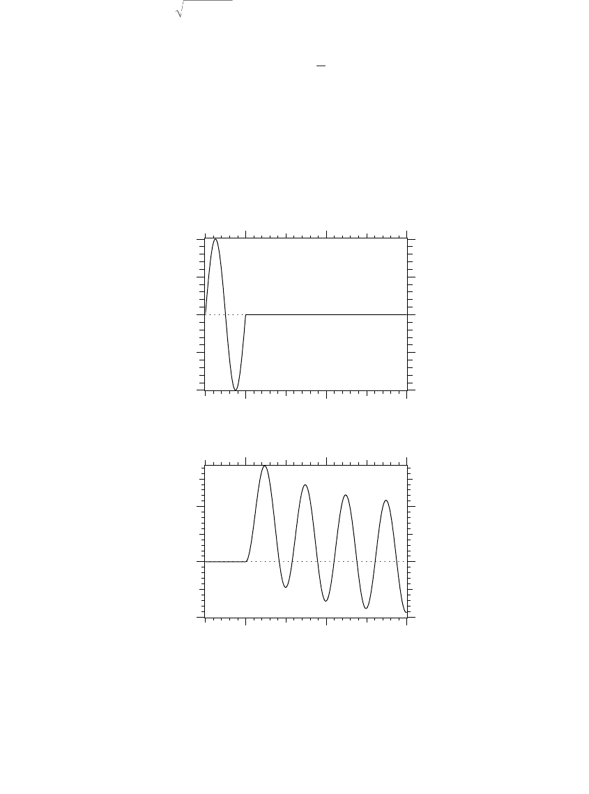
X/R = • is 2 per unit. Figure 7.13 shows an example of an offset fault current.
If a phase faults at the natural zero crossing (b = q), no offset occurs. The
highest magnitude of the dc component occurs when the fault happens 90
o
from the natural zero crossing of the circuit (when b = q±p/2). The highest
FIGURE 7.13
Example of an asymmetric fault with X/R = 10 which initiated when the closing angle b = 0,
which is when the voltage crosses zero.
IVRX
rms
=+/
22
tan
-1
X
R
0 2 4
-1.0
-0.5
0.0
0.5
1.0
0 2 4
-1
0
1
Time, cycles
Voltage
[per unit]
Current
[per unit]
Time, cycles
1791_book.fm Page 327 Monday, August 4, 2003 3:20 PM
(C) 2004 by CRC Press LLC

328 Electric Power Distribution Handbook
dc offset does not align with the highest peak asymmetric current (which is
the sum of the ac and decaying dc component). The peak current occurs
when the closing angle b= 0 for all X/R ratios (b = 0 when the fault occurs
at a voltage zero crossing). The ratio of the peak current I
p
to the rms current
I
rms
can be approximated by
This is the most industry-accepted approximation that is used, but it gives
an approximation that is slightly low. A more accurate approximation can
be found (St. Pierre, 2001) with
where t is a fictitious time found with
In addition to causing a higher peak magnitude, asymmetry also causes
a longer first half cycle (important for fuse operating time) and much higher
first half cycle ÚI
2
dt. The occurrence of asymmetry is reduced by the fact
that most faults occur when the voltage is near its peak (Figure 7.5). In a
circuit with a high X/R ratio, when the voltage is at its peak, the fault current
is naturally near zero. Therefore, for most faults, the asymmetry is small,
especially for line-to-ground faults. For two- or three-phase faults where
each phase is faulted simultaneously (as can happen with lightning), asym-
metry is much more likely.
Asymmetry is important to consider for application of cutouts, circuit
breakers, and other equipment with fault current ratings. Equipment is gen-
erally tested at a given X/R ratio. If the equipment is applied at a location
where the X/R ratio is higher, then the equipment may have less capability
than the rating indicates. Equipment often has a momentary duty rating
which is the short-time (first-cycle) withstand capability. This is strongly
influenced by asymmetry.
Other impacts of asymmetry include:
• Asymmetry can saturate current transformers (CTs). On distribution
circuits, overcurrent relays should still operate although they could
be more susceptible to miscoordination.
• Fuses respond to ÚI
2
dt, so asymmetrical current melts the link sig-
nificantly faster.
I
I
ee
p
rms
R
X
R
X
=+
È
Î
Í
˘
˚
˙
=+
È
Î
Í
˘
˚
˙
=
-+ -
21 21
2(/)
sin
qp p
qqp for / 2
I
I
e
p
rms
R
X
=+
È
Î
Í
˘
˚
˙
-
21
2pt
t= -
-
049 01
1
3
..e
X
R
1791_book.fm Page 328 Monday, August 4, 2003 3:20 PM
(C) 2004 by CRC Press LLC
Faults 329
• Asymmetry can foul up fault-location algorithms in digital relays
and fault recorders.
7.2.4 Secondary Faults
Secondary faults vary depending on the transformer connection and the type
of fault on the secondary. For a standard single-phase 120/240-V secondary
for residential service, two faults are of interest: a fault from a phase to the
neutral and a fault from one of the hot legs to the other across the full 240
V. The impedance to the fault includes the transformer plus the secondary
impedance. The secondary current for a bolted fault across the 240-V legs
(between the two hot legs) is
where
I
240
= Secondary current, symmetrical A rms for a 240-V fault (phase-to-
phase)
R
T
= Transformer full-winding resistance, W at 240 V (from terminals X1
to X3)
X
T
= Transformer full-winding reactance, W at 240 V (from terminals X1 to
X3)
R
S
= Secondary conductor resistance to a 240-V fault, W/1000 ft
X
S
= Secondary conductor resistance to a 240-V fault, W/1000 ft
L = Distance to the fault, ft
and
where
S
kVA
= transformer rating, kVA
W
CU
= W
TOT
– W
NL
= load loss at rated load, W
W
TOT
= total losses at rated load, W
W
NL
= no-load losses, W
Z
%
= nameplate impedance magnitude, %
I
R
RL
X
XL
T
S
T
S
240
22
240
1000 1000
=
+
Ê
Ë
Á
ˆ
¯
˜
++
Ê
Ë
Á
ˆ
¯
˜
R
W
S
Z
Z
S
XZR
T
CU
kVA
T
kVA
TTT
=
=
=-
0 0576
0 576
2
22
.
.
%
1791_book.fm Page 329 Monday, August 4, 2003 3:20 PM
(C) 2004 by CRC Press LLC

330 Electric Power Distribution Handbook
For a short circuit from one of the hot legs to the neutral, both the trans-
former and the secondary have different impedances. For the transformer,
the half-winding impedance must be used; for the secondary, the loop
impedance through the phase and the neutral should be used.
where
I
120
= Secondary current in symmetrical A rms for a 120-V fault (phase-to-
neutral)
R
T1
= Transformer half-winding resistance, W at 120 V (from terminals X1
to X3)
X
T1
= Transformer half -winding reactance, W at 120 V (from terminals X1
to X3)
R
S1
= Secondary conductor resistance to a 120-V fault, W/1000 ft
X
S1
= Secondary conductor resistance to a 120-V fault, W/1000 ft
L = Distance to the fault, ft
In absence of better information, use the following impedances for trans-
formers with an interlaced secondary winding:
R
T1
= 0.375R
T
and X
T1
= 0.3X
T
And use the following impedances for transformers with noninterlaced
secondary windings:
R
T1
= 0.4375R
T
and X
T1
= 0.625X
T
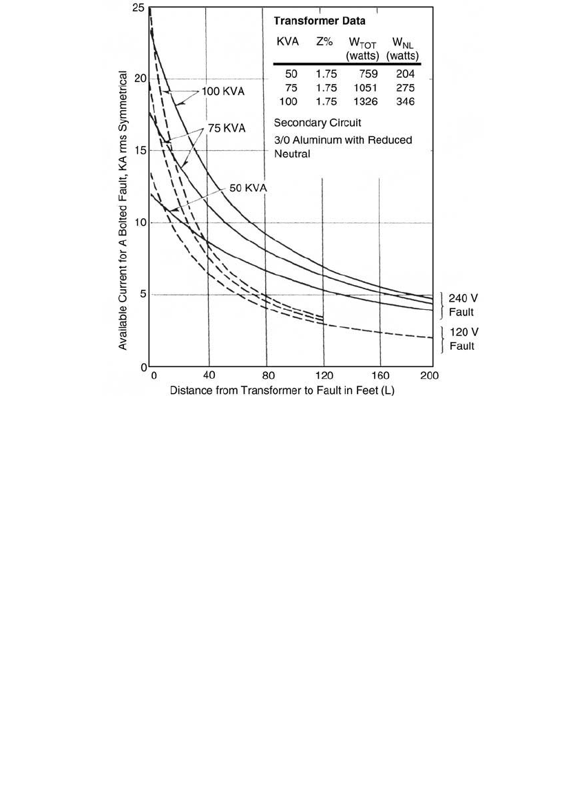
Figure 7.14 shows fault profiles for secondary faults on various size trans-
formers. The secondary is triplex with 3/0 aluminum conductors and a
reduced neutral. It has impedances of
R
S
= 0.211 W/1000 ft X
S
= 0.0589 W/1000 ft
R
S1
= 0.273 W/1000 ft X
S1
= 0.0604 W/1000 ft
The secondary has significant impedances; fault currents drop quickly
from the transformers. Close to the transformer, line-to-neutral faults are
higher magnitude. At large distances from the transformer, the secondary
impedances dominate the fault currents. Faults across 240 V are normally
higher magnitude than line-to-neutral faults.
I
R
RL
X
XL
T
S
T
S
120
1
1
2
1
1
2
120
1000 1000
=
+
Ê
Ë
Á
ˆ
¯
˜
++
Ê
Ë
Á
ˆ
¯
˜
1791_book.fm Page 330 Monday, August 4, 2003 3:20 PM
(C) 2004 by CRC Press LLC
Faults 331
Normally in secondary calculations, we can ignore the impedance offered
by the distribution primary. The primary-system impedance is usually small
relative to the transformer impedance, and neglecting it is conservative for
most uses. On weak distribution systems or with large, low-impedance
distribution transformers, the distribution system impedance plays a
greater role.
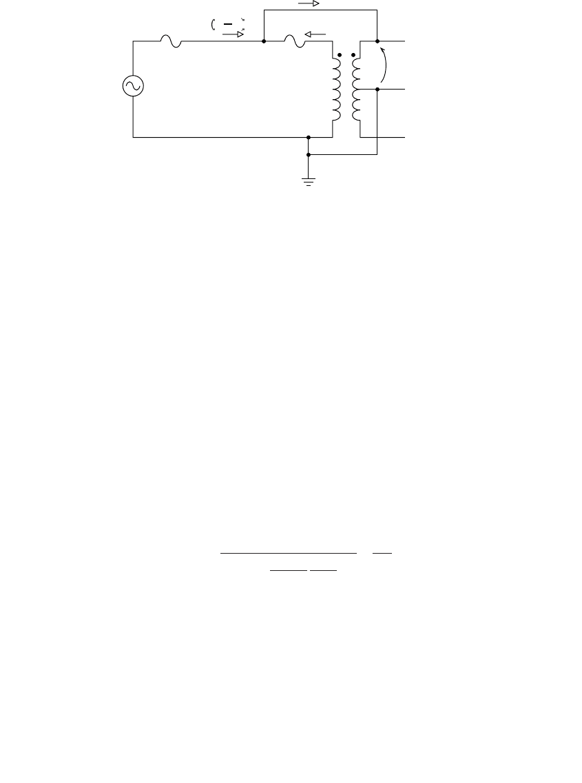
7.2.5 Primary-to-Secondary Faults
Faults from the distribution primary to the secondary can subject end-use
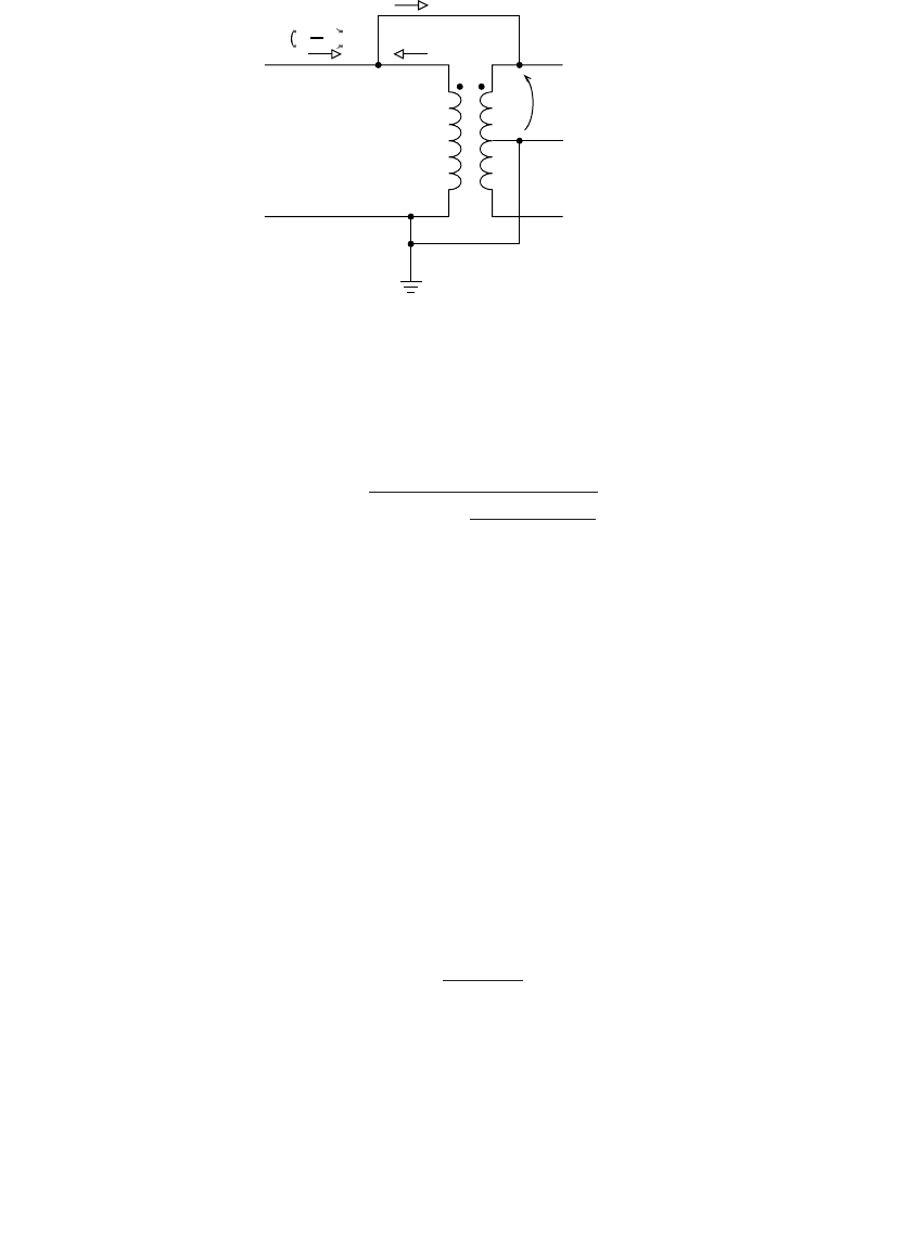
equipment to significant overvoltages. Figure 7.15 shows a circuit diagram
of a fault from the primary to a 120/240-V secondary. This type of fault can
occur several ways: a high-to-low fault within the transformer, a broken
primary wire falling into the secondary, or a broken primary jumper. As we
will discuss, the transformer helps limit the overvoltage. Having the primary
fall on the secondary does not automatically mean primary-scale voltages
in customers’ homes and facilities.
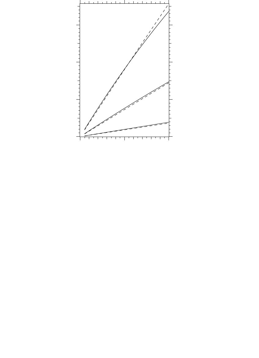
FIGURE 7.14
Fault profiles for 120/240-V secondary faults (R
T1
= 0.375R
T
, and X
T1
= 0.5X
T
). (From ABB Inc.,
Distribution Transformer Guide, 1995. With permission.)
1791_book.fm Page 331 Monday, August 4, 2003 3:20 PM
(C) 2004 by CRC Press LLC
332 Electric Power Distribution Handbook
The per-unit secondary voltage for a fault from the primary to the second-
ary (PTI, 1999) is
where
V
s
= secondary voltage, per unit at 120 V
n = transformer turns ratio from the primary voltage to the half-voltage
secondary rating (normally 120 V)
I
kA
= available primary fault current for a single line-to-ground fault, kA
S
kVA
= transformer rating, kVA
Z
%
= half winding impedance of the transformer, %
V
kV
= primary line-to-ground winding rated voltage, kV
Figure 7.16 shows the per-unit overvoltage for various transformer
sizes. Surprisingly, the primary voltage does not impact the overvoltage
significantly. The overvoltage equation in per unit reduces (PTI, 1999) to
approximately
The overvoltage increases with higher available fault current, higher
impedance transformers, and smaller transformers. For all but the smallest
transformers with the highest impedance, the overvoltage is not too hazard-
ous. But, if a fuse operates to separate the transformer from the circuit but
FIGURE 7.15
Fault from the primary to a 120/240-V secondary circuit.
Primary
Fault from the primary
to the secondary
Secondary
V
s
I
p
nI
p
n 1 I
p
V
n
n
S
V I Z
s
kVA
kV kA
%
=
+-11
10
2
()
V
.ZI
S
s
%
kA
kVA
ª
12
1791_book.fm Page 332 Monday, August 4, 2003 3:20 PM
(C) 2004 by CRC Press LLC
Faults 333
leaves the primary-to-secondary fault, the fault imposes full primary voltage
on the secondary (at least until the first failure on the secondary system).
Such a condition can occur when the fault starts on the primary side above
the transformer fuse (see Figure 7.17). If the transformer fuse blows before
the upstream line fuse, the secondary voltage rises to the primary voltage.
If the fault is below the transformer fuse, it does not matter which fuse blows
first; either clears the fault.
The example in Figure 7.15 shows a fault to the secondary leg that is in
phase with the primary (off of the X1 bushing of the transformer). A fault
to the other secondary leg (off of X3) has very similar effects; the voltages
and currents are almost the same, so the equations and graphs in this section
also apply.
Although the transformer helps hold down the overvoltage, the primary-
to-secondary fault may initiate a sizeable switching transient that could
impact end-use equipment.
With most line fuses and transformer fuses used, the line fuse will clear
before the transformer fuse and before the transformer suffers damage (good
news on both counts). Even though the upstream fuse is larger, it sees (n – 1)
FIGURE 7.16
Secondary voltage during a fault from the primary to a 120/240-V secondary circuit. The solid
lines are for a 4.8-kV circuit, and the dashed lines are for a 34.5-kV circuit. The results assume
that Z
%
= 3%.
10 kVA
25 kVA
100 kVA
0 5 10
0
1
2
3
Available primary fault current, kA
Secondary voltage, per unit
1791_book.fm Page 333 Monday, August 4, 2003 3:20 PM
(C) 2004 by CRC Press LLC
334 Electric Power Distribution Handbook
times the fault current. With the primary fault above the transformer fuse,
the transformer fuse is more likely to operate before the line fuse with
• Small transformer fuses — Another reason not to fuse transformers
too tightly; smaller, fast transformer fuses are more likely to clear
before an upstream device.
• Upstream breaker or recloser — If the upstream device is a circuit
breaker or recloser instead of a fuse, the tripping time is much longer,
especially on a time-delayed trip (but even a fast trip is relatively
long). If a circuit breaker is upstream of the transformer, the trans-
former fuse is likely to blow before the circuit breaker for locations
with high fault currents and with small transformer fuses.
A more detailed analysis of the coordination of the two devices requires
using the time-current characteristics of each of the protective devices along
with the currents. The current into the primary winding, I
p
in kA is
Again, the upstream device sees (n – 1)I
p
, which is almost the full available
current for a single line-to-ground fault, I
kA
.
A transformer with a secondary circuit breaker (as in a completely self-
protected transformer, a CSP) has another possible mode where the trans-
former separates. If the secondary circuit breaker opens before the upstream
primary device, the high-to-low fault raises the secondary voltage to the
primary voltage. The secondary circuit breaker may not be able to clear the
FIGURE 7.17
Fault from the primary to a 120/240-V secondary circuit.
Fault from the primary
to the secondary
Secondary
Line fuse
or breaker
or recloser
Transformer
fuse
V
s
I
p
nI
p
n 1 I
p
I
I
n
I
n
V
S
Z
I
n
p
kA
kA kV
kVA
%
kA
=
-+
-
ª
()
()
1
10
1
1791_book.fm Page 334 Monday, August 4, 2003 3:20 PM
(C) 2004 by CRC Press LLC
Faults 335
fault because the arc recovery voltage is much higher than the rating for the
secondary circuit breaker; this is good news in that it helps protect end-use
equipment from extreme overvoltages, but the secondary circuit breaker may
fail trying to clear the fault. If the upstream device is a fuse, the fuse will
probably clear before the secondary circuit breaker opens, but if the upstream
device is a circuit breaker, the secondary circuit breaker will probably try to
open first.
7.2.6 Underbuilt Fault to a Transmission Circuit
Faults from transmission circuits to distribution circuits are another hazard
that can subject distribution equipment and customer equipment to
extremely high voltages. Consider the example in Figure 7.18 of a fault from
a subtransmission circuit to a distribution circuit.
As is the case for primary-to-secondary faults discussed in the previous
section, overvoltages are not extremely high as long as the distribution
circuit stays connected. But if a distribution interrupter opens the circuit,
the voltage on the faulted distribution conductor jumps to the full transmis-
sion-line voltage. With voltage at several times normal, something will fail
quickly. Such a severe overvoltage is also likely to damage end-use equip-
ment. The distribution interrupter, either a circuit breaker or recloser, may
not be able to clear the fault (the recovery voltage is many times normal);
it may fail trying.
Faults further from the distribution substation cause higher voltages, with
the highest voltage at the fault location. Current flowing back towards the
circuit causes a voltage rise along the circuit.
While one can use a computer model for an exact analysis (but it is not
possible with most standard distribution short-circuit programs), a simpli-
fied single-phase analysis (assuming a wye – wye transformer) helps frame
the problem. The fault current is approximately
FIGURE 7.18
Example of a fault from a transmission conductor to a distribution conductor.
69 kV
12.5 kV
fault
1791_book.fm Page 335 Monday, August 4, 2003 3:20 PM
(C) 2004 by CRC Press LLC