Tong W. Wind Power Generation and Wind Turbine Design
Подождите немного. Документ загружается.


Design and Development of Megawatt Wind Turbines 205
To illustrate a nominal set of ICs for today’s mainstream MW turbines, the
forgoing procedure was followed with the following assumptions:
Market settings for the U.S. w/ average construction conditions 1.
Average results of value analysis using 15, 50, 100, 200 and 300 MW blocks of 2.
power (land is not a constraint)
WTG ratings in the 1 3. − 5 MW size range (note that the 4 − 5 MW rated machines
assume logistics cost is no worse than 2 − 3 MW machines), i.e. no signifi cant
increase in logistics capability or cost
Assumes 20-year project fi nancials that are levelized 4.
6 5. − 10% discount rate
8.5 m/s AMWS w/ 12% TI 6.
1.55 $c/kWh levelized PTC 7.
5.50 $c/kWh levelized PPA 8.
Examples of the ICs that result from this generalized value analysis are shown
in Table 2 [ 18 ]. The ICs are very useful for making fi rst assessments of component
technology effects on the overall MW WT design. For example, a 1 pt increase in
AEP for a particular technology enhancement results in a 0.08 or about 1/10th of
a penny reduction in LCOE and an increase in TV of $20.3K/MW of machine rat-
ing. Thus, if a 2.5 MW turbine was to be used in a given WPP specifi cation; 2.5 ×
20.3 = $50.75K/turbine of TV results.
Similarly, if there were a 1 pt increase in turbine cost, this would result in a 0.05-cent
increase in LCOE and an $8.6K/MW decrease in TV. Using the 2.5 MW turbine
example, this would result in a $21.5K/turbine reduction in TV. Taken together
with the AEP example, if one was able to introduce a component to a new WT
design that increased AEP by 1 pt with a cost increase of 1 pt, the net result would
still be a benefi t of $50.75K − $21.5K = $29.25K of TV per turbine. Clearly any
number of scenarios can result for evaluating new technologies, and careful
appraisal using ICs for well understood value analysis assumptions are very useful
for determining the merits of potential technology.
3.8 Continual cycles of re-focus; systems − components − systems
One of the most important aspects of a successful MW WT program is the organiza-
tion’s ability to continually re-focus across all aspects of the design from systems to
Table 2: ICs for assessing new component technologies.
LCOE Total value
Variable $c/k/Wh /1 pt increase k$/MW/1 pt increase
AEP -0.8, +/- 0.005 20.3, +/- 0.13
Turbine cost 0.05, +/- 0.004 -8.6, +/- 0.71
BOP cost 0.02, +/-0.002 -4.7, +/-0.55
O&M cost 0.005, +/-0.001 -0.9, +/- 0.37
Transportation 0.003, +/- 0.000 -0.7, +/-0.07
+/- 95% confi dence +/- 95% confi dence
206 Wind Power Generation and Wind Turbine Design
components and back again. This process is repeated throughout the design phases
to ensure the best of all requirements are considered and optimized, while remaining
agile to ever changing external factors; e.g. markets, emergent technologies, etc.
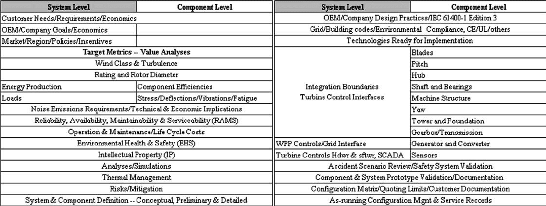
Table 3 provides a simplifi ed listing of considerations as a starting point for the
turbine designer and illustrates just how challenging this process can be. There are
additional levels of systems and sub-systems and all of these and their inter-
relationships should be thoroughly understood. Many of the items in the system
level have direct counterparts in the component level, while others must be con-
sidered in both systems and components. Without exception, truly optimized
MW WT products have component level characteristics that are performance
enablers for meeting overall system level requirements.
4 MW WT design techniques
This section pulls together all of the pieces that go into a well-organized new
turbine design. Requirements are emphasized and optional approaches presented.
The 10-turbine analysis group is used together with the value analysis methodol-
ogy to estimate turbine loads and their effect on component mass and cost. Com-
ponent and turbine results are plotted for the 10-turbine analysis group against the
backdrop of the entire industry.
4.1 Requirements
The customer’s highest priority is investing in equipment and power plant infra-
structure that is affordable to fi nance and continues to operate cost effectively for
its entire 20-year lifetime. Thus, it is imperative that new turbine designs consider
reliability, availability and maintenance from the very beginning. The ease of oper-
ating and deriving profi ts from the WPP is as important as the initial cost. The need
for specially trained personnel or specialists is another important consideration early
in the equipment selection process. The successful turbine designer accounts for all
of these and the individual signifi cant requirements of prospective customers.
4.1.1 Turbine
While there are numerous possibilities for WT system confi gurations, the major-
ity of modern equipment consists of a horizontally confi gured drivetrain with two
or three blades attached to an upstream facing rotor. The rotor is supported at the
tower top using at least one rotor bearing and a main shaft that drives a generator
system for power conversion. The drivetrain and power conversion system are
located on top of the tower within a nacelle enclosure to protect the power conver-
sion equipment from the environment. The nacelle is equipped with a yaw system
that is used under normal operating conditions to point and maintain the rotor facing
upstream into the wind.
It is beyond the scope of this article to discuss the details for why this confi gura-
tion has become the de-facto standard. Suffi ce to say that many other confi gurations
have been investigated, and in almost all cases, the reasons boil down to longevity
(through relentless unsteady operational conditions and extremes), reliability and
Design and Development of Megawatt Wind Turbines 207
Table 3: Example elements for successful MW WT design.
208 Wind Power Generation and Wind Turbine Design
costs. This again comes back to the central theme of value analysis, without which
others will continue to follow paths of whimsical or even elegant WT concepts, only
to eventually return to the same place as the rest of the industry – three-bladed
upwind WTs for reliable and economical WPP installations. This is not to say
there will not be a future breakthrough that shatters this paradigm, but a strong
value analysis must accompany any such breakthrough.
4.1.2 Reliability
Reliability is the ability of the WT to perform at expected cost levels while producing
the expected annual energy production (AEP) based on the actual wind conditions.
Poor reliability directly affects both the project’s revenue stream through increased
O&M costs and reduced availability to generate power due to turbine downtime [ 19 ].
4.1.3 Availability
If a turbine were always ready to produce electricity when the wind speed is within
the range of the power curve, it would then have 100% availability. This has been an
area of dramatic improvement in the past few years with 98% availability typical for
the most popular machines today versus 85% just 6 − 8 years ago. Proven component
technologies must be integrated into an overall system that is value-effective and
robust for high availability.
4.1.4 Maintainability
According to wind-energy-the-facts.org [ 20 ], “Typical routine maintenance time
for a modern WT is 40 hours per year.” What are the value-effective ways to reduce
O&M time and costs? Maintainability and serviceability are closely related design
goals that provide the backstop for ensuring the highest possible availability. All
machines require some amount of maintenance over their design life. However the
best machine fi nds the value-effective minimum maintenance strategy and stream-
lines the maintenance that must be done. Should a part or component fail for any
reason, cost-effective design provisions that minimize service and logistics costs
should be integrated into the design.
4.2 Systems
The overall product requirements and design features for achieving business
objectives include different system level views − continually revisit these levels
throughout the product development process to ensure optimal results.
4.2.1 New WT design
A wind turbine generator (WTG) converts the kinetic energy of the wind into
mechanical shaft power to drive a generator that in turn produces electrical energy.
A WT is composed of fi ve main elements:
Rotor made up of rotor blades that use aerodynamic lift to convert wind energy •
into mechanical energy.
A rotor bearing fi xed on a structure that causes a defi ned rotation of the rotor and •
leads to conversion of the aerodynamic wind energy into a rotational shaft torque.
Design and Development of Megawatt Wind Turbines 209
A yaw system maintains the horizontal rotor axis pointing upstream into the wind.
A power conversion system that converts the low-speed rotational energy into •
suitable shaft power to drive an electrical generator.
A tower and foundation structure to support the rotor and generator system at a •
height that harvests the most amount of energy for an acceptable capital cost.
An electrical power distribution system that supplies the energy to the consumer •
in compliance with local grid code and system requirements.
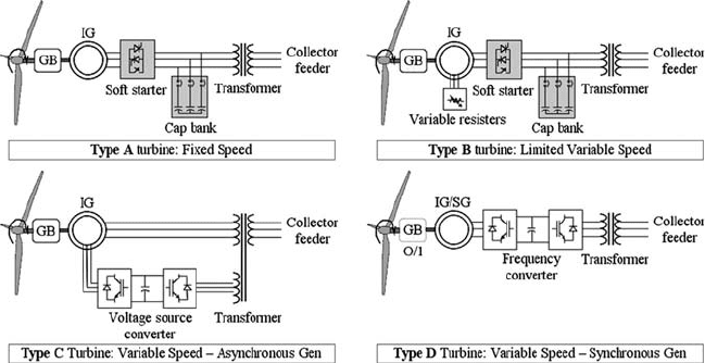
4.2.2 Mechanical − electrical power conversion architecture
Figure 9 shows the four main types of WT architecture that have been employed
according to Wojszczyk et al. [ 21 ]. Types A and B are older and less prevalent
confi gurations, while Types C and D comprises the mainstay of modern MW
WT offerings.
Type A is the oldest and utilizes a squirrel cage induction generator (SCIG)
directly coupled to the electrical grid. It may incorporate a soft starter to limit in-
rush current during start-up conditions. The rotor is connected to the generator
through a gearbox and can often run at two different (but constant) speeds. This is
achieved by changing the number of poles of the stator winding. The generator
always consumes reactive power, and therefore this has to be compensated by
capacitor banks to optimize the power factor and maintain the voltage level.
Type B introduces a variable resistor in the rotor circuit of a wound rotor induction
generator (WRIG). This can be done using slip rings or the resistors and electronics
can be mounted within the rotor. The variable resistors control the rotor currents to
maintain constant power output and allow the WT to have dynamic response during
grid disturbances. Some degree of self-protective torque control and energy capture
range is provided by ± 10% speed variation.
Type C is known as the double fed induction generator (DFIG). It improves on the
Type B design by adding variable excitation (instead of resistance) to the rotor cir-
cuit. The generator stator winding is directly connected to the grid and the rotor
Figure 9 : The four main types of WT mechanical − electrical power conversion.
210 Wind Power Generation and Wind Turbine Design
winding is fed from the grid using voltage source converters. A rotor-side converter
is connected back-to-back with a grid side converter and requires only about 1/3 of
the overall turbine power rating to accomplish a wide range of output power control.
The system permits relatively fast response to signifi cant grid disturbances and
advantages for reactive power supply to the grid, power quality and improved har-
monics. Type C is a more expensive architecture than Type A or B designs, but it is
popular for its advantages.
Type D uses a synchronous generator that can have either a wound rotor or can be
excited using permanent magnets. This is also known as “full-power conversion”
and provides design and operational fl exibility including the option of eliminating
the gearbox. Variable speed operation is achieved by connecting the synchronous
generator to the grid through the frequency converter. Type D turbines are better than
Type C turbines despite the higher cost, as they are decoupled from the grid via
power electronics, resulting in excellent capability for power quality and reactive
power. Use of permanent magnets in the generator rotor offers the advantage of
greater effi ciency and high power density, resulting in more compact generators.
4.2.3 Governing dimensional considerations
One of the most important design drivers of a WT is the closest approach of the
blade tip to the tower. The baseline axial distance from the blade tip to the tower
wall for the fully unloaded blade in the 6 o’clock position is known as the “static
clearance.” The amount of clearance remaining for the actual turbine operational
conditions is a function of the loads imparted on the rotor blade and tower, the
blade geometry, stiffness, mass, and how the blades are positioned relative to the
rotor hub and the turbine [ 22 ]. Typical minimum operational blade-tower clear-
ance is 1/3 of the static clearance or a distance of one tower radius relative to the
tower diameter at the same elevation of the passing tip [59].
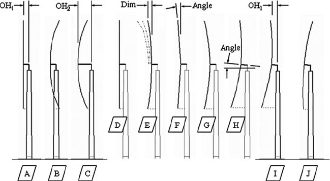
Blade-tower operational clearance considerations are shown in Fig. 10 relative
to the wind fl owing from the left to the right. Starting from the left, sketch /A/ is
Figure 10 : Blade-tower clearance for upwind facing WT.
Design and Development of Megawatt Wind Turbines 211
for the baseline condition of zero wind and rotor speed. There is a set amount of
rotor “overhang” (OH
1
) and the blades are positioned within a vertical rotor plane.
Sketch /B/ depicts an extreme load case for the swept surface of the rotor plane under
operational wind conditions. Clearly this scenario is not acceptable, as the blades
will interfere with the tower. In an attempt to gain clearance by moving the rotor
forward, sketch /C/ shows that even with signifi cant increase of the overhang dimen-
sion OH
2
, the minimum clearance is still not acceptable. Increasing overhang is very
costly as it requires signifi cantly more mass in the machine head (MH) structure to
support the rotor mass and operational loads due to the longer lever arm.
Sketch /D/ shows the same starting assumption as /A/ with the rotor in a vertical
plane. Various types and amounts of “zero wind” geometry are depicted for
sketches /E/ through /H/:
/E/ – Blade prebend, an amount of forward reaching curvature characterized by •
the axial dimension measured from the blade tip vertical plane to the rotor cen-
tre vertical plane. Typical values are 1 − 3 m (larger values are anticipated as
rotor diameters continue to increase).
/F/ – Blade cone, an amount of forward reaching cone characterized by the cone •
angle measured between the normal vector at the blade root attachment and the
rotor centre vertical plane. Typical values are 2 − 6°.
/G/ – As typically the case use a combination of blade prebend and cone. •
/H/ – Tilt the rotor and the drivetrain by a small angle relative to the horizontal •
plane. Typical values are 2 − 6°.
Using rotor /H/, sketch /I/ depicts a return of the rotor overhang to the more
economical OH
1
value. Extreme loadings for this arrangement result in sketch /J/.
Since the blade-tower minimum clearance exceeds 1/3 the static clearance, this
combination of design parameters provides a solution to the OH
1
constraint. All
new turbine concepts must go through this type of optimization process, and be
revisited throughout the structural design phases to ensure loads and defl ections
are accommodated.
4.2.4 WT system modelling for determining design loads
There are a number of WT structural calculation programs currently being used by
WT designers. These include readily available models using commercial fi nite ele-
ment analysis (FEA) programs such as ADAMS, ANSYS and NASTRAN. Some
of the most widely used programs specifi cally developed within the WT design
community are BLADED and FLEX5. FLEX5 has the advantage of wide industry
support and open source code, making it the preferred platform for many OEMs.
One drawback for FLEX5 from the conceptual design perspective (where rapid
solution times are needed to explore a large design space) is the relatively long run
times. Usually 1 − 2 h are required to run a turbine confi guration through a reduced
suite of load cases using a dual-processor workstation. This can be improved with
ever-faster hardware, but the preferred method for performing value analyses sets
up a large number of cases using the method of design of experiments (DOEs).
These results are used to populate the design space with solutions that can later be
used to interpolate conceptual designs in seconds instead of hours. This “DOE
212 Wind Power Generation and Wind Turbine Design
loads engine” makes it possible for the turbine designer to explore more options in
a shorter period of time and quickly adapt the overall value analysis program for
emergent component technology assessment.
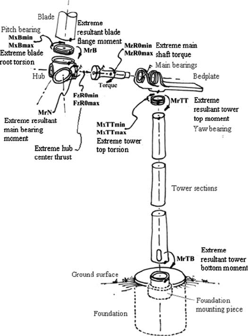
Today, FLEX5 has as many as 34 degrees of freedom modelled for the upwind
three-bladed WT. There is a great deal of data available from the normal solution
results, but there is a smaller subset of this data that has the greatest impact on the
initial sizing of turbine components. Using FLEX5 naming conventions, Fig. 11
shows these primary forces and moments and the components they are related to
and act upon.
4.2.5 Load calculations
To gain an appreciation for the level of extreme loads developed in a WT,
and how they change with turbine size, a 10-turbine analysis group of today’s
industry average technology was undertaken. These turbine design cases are
Figure 11 : Primary extreme loads nomenclature and locations.
Design and Development of Megawatt Wind Turbines 213
geometrically scaled along the industry trend projected up to 10-MW size. The
basic WT parameters were presented in Table 1 earlier in this chapter.
One of the most important features for a value analysis program is the selection
of component technologies that are used to describe the turbine confi gurations.
Some components, such as bearings and gearboxes, exhibit some degree of dis-
crete changes with increased size or loadings such as the number of main shaft
bearings or the number of stages within the gearbox. These details are important
to address in subsequent design iterations, but for illustrative purposes the value
analysis is performed using a blend of turbine component technologies to avoid
discontinuities and demonstrate smooth nominal values for loads, mass and
value metrics.
4.2.6 Load cases
There are a large number of different types of load cases that are examined through-
out the various design phases. Load cases account for every conceivable loading
situation, and all of the possible confi guration variations, operational conditions
and extremes that could be encountered over the 20-year design life for the turbine
and its installation environment. It has been found that a specifi c subset of these
cases actually affect the conceptual design of a WT, and working with this subset
greatly simplifi es this early phase in the design process. Expected extreme loads
will have an impact on the primary or fi rst-order sizing of components. Expected
dynamic loads affect the fatigue life of components and consequently, the fi nal
sizing of components. The full range of design load cases should ultimately be
examined in order to gain a complete understanding for the behaviour of the WT,
particularly for the detailed design phase. A set of specifi c load cases will eventu-
ally be required by a certifi cation agency (if applicable) such as Germanischer
Lloyd (GL), "Guideline for the Certifi cation of Wind Turbines" [ 23 ].
4.2.7 Load levels
To gain a better appreciation for the level of forces and moments for these large
machines, it is useful to make an analogy with another machine. An M1A2 Abrams
main battlefi eld tank has a mass of 63 tonnes fully loaded [ 24 ]. This can be used
as a convenient reference for the level of loads calculated throughout the WT;
e.g. 63 tonnes acting at the end of a 1-m moment arm is “one tank-meter.”
4.2.8 Impact to system design
Load calculations lead to the provisioning of strength requirements for the WT,
and fl ow down into component requirements. At the system level, the turbine must
be able to resist being pushed over by the thrust imparted on the rotor in the down-
wind direction, while at the same time carrying the low-speed shaft torque from
the rotor through to the generator. Rotor loads must be carried into the MH struc-
ture and passed into the tower top. These loads and the top head mass (THM) are
carried through to the tower bottom and foundation, with the soil bearing pressure
being the last interface to distribute these loads into the earth.
214 Wind Power Generation and Wind Turbine Design
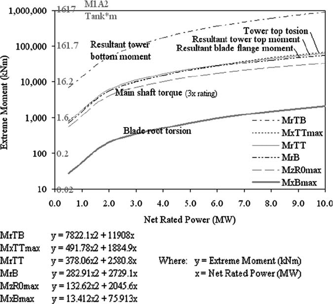
Figure 12 shows the primary extreme moment results for the 10-turbine analysis
group. The tower overturning moment is the largest value due to the thrust force
acting over the long lever arm of the tower height.
The main shaft torque dominates the loads carried by the MH structure. While
many of the load cases impart signifi cant forces and moments to this structure, the
main shaft torque drives the overall level. A 3-MW WT must resist about 7330 kNm
of moment about the shaft in the MH. This is equivalent to about 12 tank-meters.
These loads increase nearly fi vefold for a turbine rated at the 10 MW level, or
about 55 tank-meters. One quickly appreciates the level of loads that this repre-
sents by imagining 55 M1A2 Abrams tanks at the end of a 1-m moment arm trying
to twist-off the top of the turbine.
The amount of thrust absorbed by the rotor and turbine support structure is
shown in Fig. 13 . A 3 MW rated WT will have about 816 kN of axial force applied
at the main shaft location, or the equivalent weight force of about 1.3 M1A2
Abrams tanks.
The previous examples are for extreme loads, but more important to consider
are the time-varying or fatigue loads, which mechanically work the structure,
Figure 12 : Calculated extreme moments for the 10-turbine analysis group.