Tong W. Wind Power Generation and Wind Turbine Design
Подождите немного. Документ загружается.

Design and Development of Megawatt Wind Turbines 225
hub technology at 10 MW is suggested to be about 75 tonnes (and even lower
if possible).
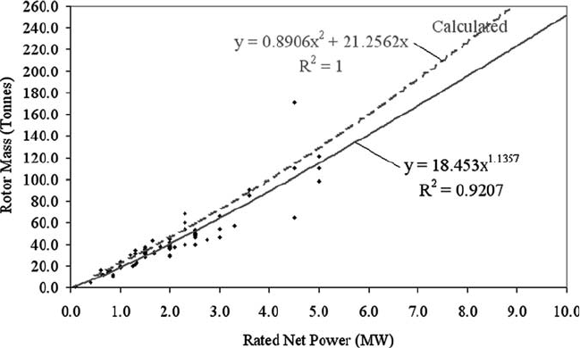
Figure 23 shows the mass for the complete rotor that includes the hub, pitch
system and blades. This complete rotor mass must be carried by the main shaft
and bearings that undergoes a wide range of torque and moment loadings. The
10-turbine analysis trend suggests a rotor mass of 300 tonnes or more for a 10
MW rated machine.
The mix of design technologies for the industry study set projects that for an
improvement in technology similar to the industry thus far; one should be able to
achieve a rotor hub with a total mass of 250 tonnes for a 10 MW turbine. A stretch
target of 150 tonnes is believed possible for improved advances in rotor hub, pitch
slew bearing and blade structural design.
With respect to attaching a hub to a main shaft, an alternative technology fea-
tures the rotor hub confi gured directly with bearings and mounted on a fi xed
axle, also known as an axle pin. This arrangement is particularly attractive for a
DD machine and is similar to the steering axle (i.e. front) wheel construction
used in motor vehicles. For this later example, the wheel is analogous to the WT
rotor blade assembly and the brake rotor disk would correspond to the DD
generator − both connected together and rotating about a fi xed axle.
4.4.4 Rotor main shaft and bearings
The main shaft is one of the primary components of the WT drivetrain system. Its
main purpose is to transfer torque from the rotor hub through to the gearbox. The
main shaft and bearings must also handle loads for the specifi ed WT design IEC
TC for a period of 20 years or more. Together with thrust, wind turbulence and
Figure 23 : Rotor mass − 10-turbine analysis compared to industry study set.
226 Wind Power Generation and Wind Turbine Design
turbine operating conditions, the main shaft must transfer the rotor plane bend-
ing moments into the tower supporting structure and ultimately into the founda-
tion (see Fig. 11 ). In addition, it must sustain transient and highly dynamic loads
caused by grid failure, over speed events, breaking, and emergency stops, as well
as loads due to extreme wind, gusting and environmental conditions.
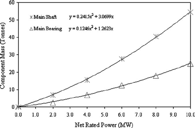
The 10-turbine analysis group mass results for the main shaft and nominal bear-
ing arrangement are shown in Fig. 24 . The main bearing trend is an average for a
single main bearing and a double main bearing type design. A single-bearing
design (e.g. GE1.5) uses one large bearing at the front of the shaft with the gearbox
and torque arms used to support the aft end of the shaft. A double-bearing design
(e.g. GE2.5) has a second independent bearing located at the aft end of the main
shaft and the main shaft supports the “fl oating” gearbox.
Figure 24 suggests a 10 MW main shaft to have a mass of nearly 55 tonnes and a
main shaft bearing or bearings of about half that amount or approximately 25 tonnes.
Using similar reasoning for technology advancement on the way to a 10 MW size
machine, it appears possible to achieve 37 and 18 tonnes for the main shaft and
bearings, respectively.
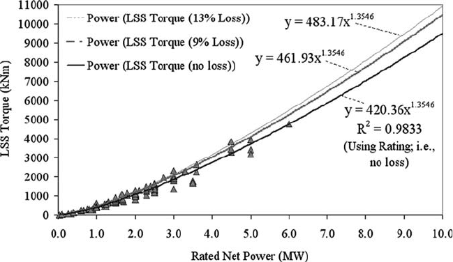
Based on the industry study set, the amount of steady-state torque being carried by
the main shaft to a generator or a combined gearbox − generator is shown in Fig. 25 .
The effect of overall mechanical and electrical losses of 9 and 13% is included to
illustrate the effect on the steady-state main shaft torque. Assuming that the losses
for advancing technology while designing for a 10 MW machine are in the 8 − 9%
range, about 10,000 kNm of torque capability is needed at the rating point. This is
equivalent to about 16.2 Abrams M1A2 tank-meters of torque. Due to grid and
Figure 24: Main shaft and bearing mass from the 10-turbine analysis group.
Design and Development of Megawatt Wind Turbines 227
transient operational considerations, max design torque of 2.5 − 3.0 times the
steady-state level is provisioned, so that the shaft and reaction confi guration would
actually be designed to accommodate 30,000 kNm or about 48.6 tank-meters.
Future large turbine main shaft and bearing technology will likely need to be
more integrated and consider cast or alternative approaches to today’s typical main
shaft forging. Taken together with the requirements for larger and heavier rotor
hubs, the fi xed axle arrangement should also be evaluated.
4.4.5 Mainframe or bedplate
The rotor and drivetrain support structure is a direct compliment and enabler to the
main shaft and bearings. The design goal is to achieve as light a structure as pos-
sible, with allowable defl ections within the overall materials and system specifi ca-
tion, yet strong and capable of resisting fatigue damage with a maintenance free
life. The amount of rotor overhang relative to the tower top centreline (see OH
1
and OH
2
in Fig. 10 ) directly affects the size and weight of the mainframe required
for a given turbine design.
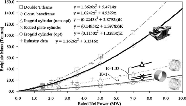
Figure 26 shows (1) today’s industry study set and (2) moving from today’s
fabricated or cast bedplate towards a canard or spaceframe structure may save
signifi cant mass [ 28 ]. Further system benefi ts should be possible for integrating
the drivetrain within these types of spaceframe structures. The heavy trend line
shown in Fig. 26 represents the conventional fabricated or cast bedplate from the
industry study set. This represents today’s technology, and is more than 20%
lighter than the double T frame used in the earliest MW WT designs. Even so,
the bedframe alone would be more than 140 tonnes at the 10-MW size if today’s
technology were to remain unchanged.
Moving towards spaceframe type designs may reduce bedplate mass on the
order of half, but this will also depend on the amount of stiffness reduction that can
Figure 25: LSS rated torque for the industry study set.
228 Wind Power Generation and Wind Turbine Design
be accommodated in the actual spaceframe design. The factor K illustrates the idea
of normalizing entitlement of the isogrid and tubular cylinder for adding mass
back into the idealized tubes to account for the main shaft bearing support, drive-
train torque and yaw deck features relative to the conventional and double T frame.
This makes it more of an apples-to-apples comparison. The 1.33 factor is purely
an estimate to make the point, and may need to be higher to yield an acceptable
design. The "optimized" isogrid cylinder would have mass strategically added to
address local high stress regions for a particular spaceframe design making it
comparable to the rolled plate cylinder.
To minimize mass to the greatest extent possible, and take full advantage of an
enveloping spaceframe type structure, large 7 − 10-MW WT designs will likely
need to incorporate some form of spaceframe-integrated drivetrain technology.
There are some OEMs starting to move in this direction.
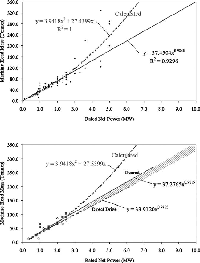
4.4.6 Machine head mass
Today’s mainframe and drivetrain components and their protective housing (i.e.
nacelle) are collectively referred to as a MH. The MH mass (MHM) is an impor-
tant consideration for larger WTs because of shipping logistics, fi eld assembly and
installation crane requirements among other things.
The solid line in Fig. 27 is an estimate of the industry study set trend for increas-
ing MHM with larger WTs. The dashed line is the trend for the 10-turbine analysis
group. Future large WTs in the 7 − 10-MW size range will need the overall MHM
targeted for the solid line or below to ensure favourable WPP economics. The
considerable divergence for the calculated trend at the larger MW ratings illus-
trates why straight scaling of existing drivetrain, bedplate and MH technologies
will not result in a cost-effective WPP.
Figure 26 : Bedplate mass – options compared to the industry study set.
Design and Development of Megawatt Wind Turbines 229
Figure 28 plots a subset of the industry data presented in Fig. 27 for MHs that
employ either a gearbox or DD. The mass of today’s DD generator technology is
nearly as much as the mass of a gearbox and high-speed generator combined.
While it appears the DD technology has a slight mass advantage over the geared
turbines, it is not signifi cant for large machines. It should be possible for a 10 MW
MH (that would otherwise be 330 − 370 tonnes) to be in the 230 − 270 tonne range
or better for new low-speed generator breakthroughs. It may also require some
Figure 27 : MHM – 10-turbine analysis compared to industry study set.
Figure 28: Geared and DD – 10-turbine analysis compared to industry study set.
230 Wind Power Generation and Wind Turbine Design
level of fi eld assembly to meet all of the logistics and crane requirements. Achieving
the lowest possible MHM while still delivering all of the functional and opera-
tional needs is a fundamental design goal, and it will require new technologies and
innovative integration approaches to develop an economical large WT MH.
4.4.7 Gearbox
A gearbox is needed to transmit torque and increase blade rotor rotational speed
to match the requirements of an electrical generator. Today’s high-speed generator
technology requires speeder gear ratio of 1:100 or more. Torque transmission must
be done with limited vibration and noise effects. Mechanical effi ciencies have to be
as good as economically feasible in order to minimize power losses in the system.
An emerging form of gearbox is a compact geared drivetrain where planetary
gearing and medium speed (speeder ratios of 1:30 to 1:40) generator technolo-
gies are combined into one mechanical − electrical system. The integrated geared
generator is lighter and more compact than conventional three-stage gearbox − generator
systems and, with fewer gears and bearings, is both more reliable and more
effi cient [ 29 ].
Future large turbine gearbox technology will likely incorporate elements of
lower overall gear ratio, reduced number of stages, or elimination of the gearbox
altogether.
4.4.8 Drivetrain dynamics
Today, WT drivetrains undergo signifi cant loading during WT operation due to
changes in environmental conditions, such as wind gusts. Future large turbine drive-
train dynamics technology will likely incorporate elements of adaptive response
and control. As speed control technology improves, loads on the drivetrain may be
reduced, improving reliability [56].
4.4.9 Rotor lock – low-speed and high-speed shafts
A rotor lock is a device that prevents shaft rotation. In the case of a main shaft or low-
speed shaft, the rotor lock is used during construction and during maintenance of the
WT. The high-speed rotor lock is used to prevent rotation of the gearbox output shaft.
Future large turbine rotor lock technology will likely be replaced with some
form of distributed system, and DDs obviate the need for a high-speed rotor lock.
4.4.10 Disk brake system and hydraulics
Future large turbine disk brake system and hydraulics technology will likely
incorporate elements of integrated generator brake design or elimination of the
disk brake system altogether due to advances in more reliable blade operation and
advanced rotor controls.
4.4.11 Flexible torque coupling
Shaft couplings are used to transmit torque from one shaft to another, as is the case
for today’s designs that incorporate a gearbox and separate generator. Flexible
couplings are used to balance radial, axial, and angular displacements. In addition,
Design and Development of Megawatt Wind Turbines 231
couplings may also provide for electrical current isolation, damping of torsional
vibrations, and absorb peak torques. Compact geared drivetrains, where the gear-
box and generator are combined into one mechanical − electrical power conversion
unit [ 29 ], as well as DD designs do not require fl exible couplings.
Future large turbine designs probably will not use fl exible torque coupling
technology.
4.4.12 Signal slip ring
A slip ring is at electro-mechanical device that allows transmission of power and
electrical signals from a stationary component to a rotating component. In the case
of a WT, the slip ring electrically connects the rotating hub to stationary equipment
in the nacelle.
Future large turbine signal slip ring technology will likely be replaced with
some form of contactless system or provide for a method of producing power
onboard the rotating frame.
4.4.13 Yaw bearing and drive system
The yaw bearing performs the function of supporting the entire THM of the WT
and permitting 360° rotation relative to the turbine tower. THM includes the MH,
hub and blades. This angular yaw positioning is required to ensure the turbine
rotor is always facing squarely into the wind. The primary considerations for the
turbine designer include:
Support THM relative all possible load inputs (i.e. forces and moments) 1.
Transmit rotor dynamic bending moments and loads 2.
Permit full 360° rotation times some number of turns (i.e. 2.5 3. × before requiring
the generator electrical cable to undergo an “untwist” operation)
Minimize the amount of motor torque required to yaw while balancing the need 4.
for bearing joint stiffness for loads transfer, particularly wind gusts
Future large turbine yaw bearing and drive system technology may incorpo-
rate elements of bearing segments and rotor assisted yaw (i.e. “fl ying” the rotor
into the wind).
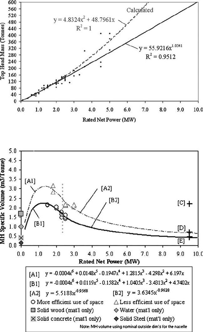
The solid line in Fig. 29 is an estimate of the industry study set trend for increasing
THM with larger WTs. The dashed line is the trend for the 10-turbine analysis group.
Future large WTs in the 7 − 10-MW size range will need THM to be targeted for the
solid line or lower to ensure favourable WPP economics. As can be seen, some of
today’s 4 − 5 MW size machines are considerably above the solid line, which is indic-
ative of excessive THM and potentially poor economic performance. Provisioning a
yaw bearing and drive system for excessively large THM only adds to the problem.
Achieving the lowest possible THM is a key design driver for the yaw bearing and
drive system, as well as for the tower support structure (among other considerations).
4.4.14 Nacelle and nose cone
Today’s nacelle and hub fairing (i.e. nose cone) are typically manufactured from
GFRP. These are generally non-structural and protect the drivetrain components
232 Wind Power Generation and Wind Turbine Design
Figure 29 : THM – 10-turbine analysis compared to industry study set.
Figure 30 : MH-specifi c volume characteristics.
Design and Development of Megawatt Wind Turbines 233
from the weather. Hub fairings are largely aesthetic, although they do enhance the
fl ow fi eld for certain turbine designs that have large nacelles (e.g. DD) and provide
anchorage for safety rails that are used to enter the hub.
Figure 30 plots the specifi c volume (m
3
/tonne) for a number of WT nacelles.
The combination of a drivetrain, bedplate and nacelle is typically referred to as the
MH and the amount of volume required to house these components are indica-
tive of material effi ciency. There appear to be two characteristic trends for the
data where the heavier line represents designs that better utilize nacelle volume.
Curve [B1] illustrates the transition from sub-MW machines to 2 − 3 MW where
personnel access and serviceability considerations peak in the 1 − 2 MW ranges.
As turbines get larger, it is projected that specifi c volumes will gradually decline.
This is due primarily to a smaller proportion of space required for personnel and
service access and the desire to minimize frontal area for better performance and
shipping logistics.
To illustrate this further, point /C/ of Fig. 30 is for a 9.5 MW turbine assuming
the same specifi c volume of around 2.2 m
3
/tonne for today’s best 1 − 2 MW
machines. Points /D/ and /E/ are for specifi c volumes of 0.7 and 0.5, respectively.
Using a MHM of 305 tonnes (representing an improved technology DD at 9.5
MW size), points /C/, /D/ and /E/ would imply MH volumes of 671, 214 and
153 m
3
, and represent cubes with side dimensions of 8.75, 5.98 and 5.34 m,
respectively.
Future large turbine nacelle and nose cone technology are likely to trend
towards their elimination. Designs using integrated drivetrain and structure will
obviate the need for a separate nacelle covering and is consistent with lower
MH-specifi c volumes for larger turbines. Elimination of a separate hub fairing
should be possible for larger turbines. Most of today’s turbine designs will not
have a measurable performance impact for eliminating the nose fairing, so
removal is further justifi ed.
4.4.15 Tower
Towers are presently constructed using steel or concrete materials. The structure is
typically tubular or lattice. Lattice towers require less material for a given strength
than tubular towers, but for labour-intensive fastener and aesthetic reasons (among
a number of others), tubular steel towers are the most prevalent. There are also
many forms of hybrid towers, which combine varying amounts of these materials
and construction types. The use of GFRP or other cost-effective materials yet to be
identifi ed may play a role in future large WT support structures.
As the industry trends towards larger power ratings and rotor diameters, towers
must also increase in height and strength. Because the tower typically comprises
over half the total mass of the WT itself (excluding the foundation), translating to
about one-fi fth of the cost, value analysis and searching for breakthrough concepts
for new tower technologies represents a signifi cant opportunity for improving
large WT economics.
The solid line in Fig. 31 is an estimate of the industry study set trend for increas-
ing tower mass with larger WTs. The dashed line is the trend for the 10-turbine
analysis group. Future large WTs in the 7 − 10-MW size range will need the overall
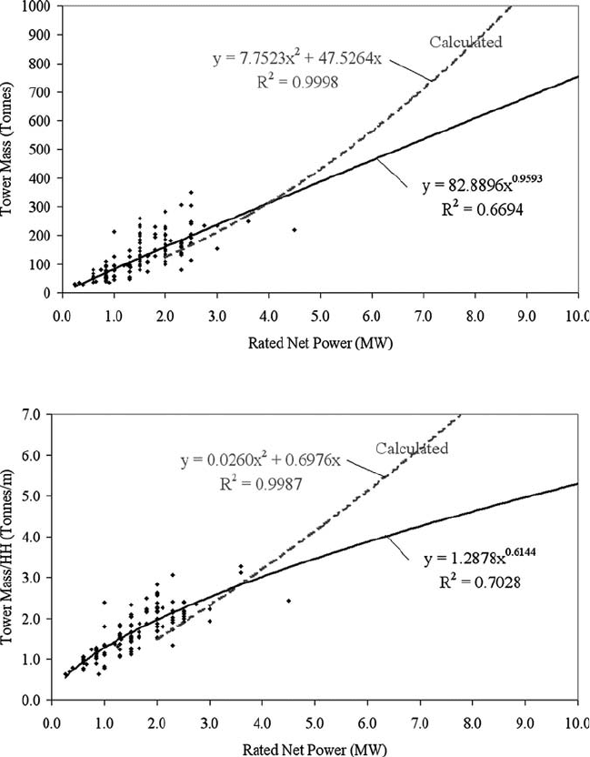
234 Wind Power Generation and Wind Turbine Design
tower mass targeted for the solid line or lower to ensure favourable WPP economics.
The considerable divergence for the calculated trend at the larger MW ratings is
particularly exasperated by the hefty tower base diameter (nearly 7 m for the 10 MW
turbine) used for the larger machines in the 10-turbine study set. Achieving the
lowest possible tower mass while still achieving all functional and operational
requirements is an important design goal.
Figure 32 is derived from Fig. 31 in terms of tower mass divided by the WT HH.
This alternative metric results in an average tower “mass per meter” of tower
height. In practice the mass per meter of the lower elevations of the tower will be
Figure 31 : Tower mass – 10-turbine analysis compared to industry study set.
Figure 32: Tower mass/HH – 10-turbine analysis compared to industry study set.