Wai-Fah Chen.The Civil Engineering Handbook
Подождите немного. Документ загружается.

46-20 The Civil Engineering Handbook, Second Edition
For plastic torsion, the sand-heap analogy has been developed, and it has similar interpretations as
those in the membrane analogy [Nadai, 1950]. Dry sand is poured onto a raised flat surface having the
shape of the cross section of the member. The surface of the sand heap so formed assumes a constant
slope. The volume of the sand heap, hence its weight, is proportional to the fully plastic torque carried
by a section.
Warpage of Thin-Walled Open Sections
For a narrow rectangular bar, no shear stresses develop along a line bisecting its thickness. This means
that no in-plane deformation can take place along the entire width and length of the bar’s middle surface.
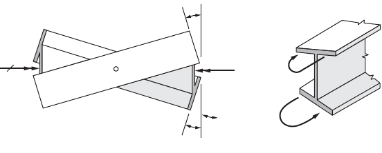
In this sense, an I section, shown in Fig. 46.19, consists of three flat bars, and during twisting, the three
middle surfaces of these bars do not develop in-plane deformations. By virtue of symmetry, this I section
twists around its centroidal axis, which in this case is also the center of twist. During twisting, as the
beam flanges displace laterally, the undeformed middle surface abcd rotates about point A, Fig. 46.19(a).
Similar behavior is exhibited by the middle surface of the other flange. In this manner, plane sections of
an I beam warp, i.e., cease to be plane, during twisting.
Cross-sectional warpage, or its restraint, may have an important effect on member strength, particu-
larly on its stiffness. Warpage of cross sections in torsion is restrained in many applications. For example,
by welding an end of a steel I beam to a rigid support, the attached cross section cannot warp. To maintain
required compatibility of deformations, in-plane flange moments M, shown in Fig. 46.19(b), must
develop. Such an enforced restraint effectively stiffens a beam and reduces its twist. This effect is local
in character and, at some distance from the support, becomes unimportant. Nevertheless, for short
beams, cutouts, etc., the warpage-restraint effect is dominant. For further details, refer to the reference
of Oden and Ripperger [1981].
Torsion of Thin-Walled Hollow Members
Unlike solid noncircular members, thin-walled tubes of any shape can be rather simply analyzed for the
magnitude of the shear stresses and the angle-of-twist caused by a torque applied to the tube. Thus,
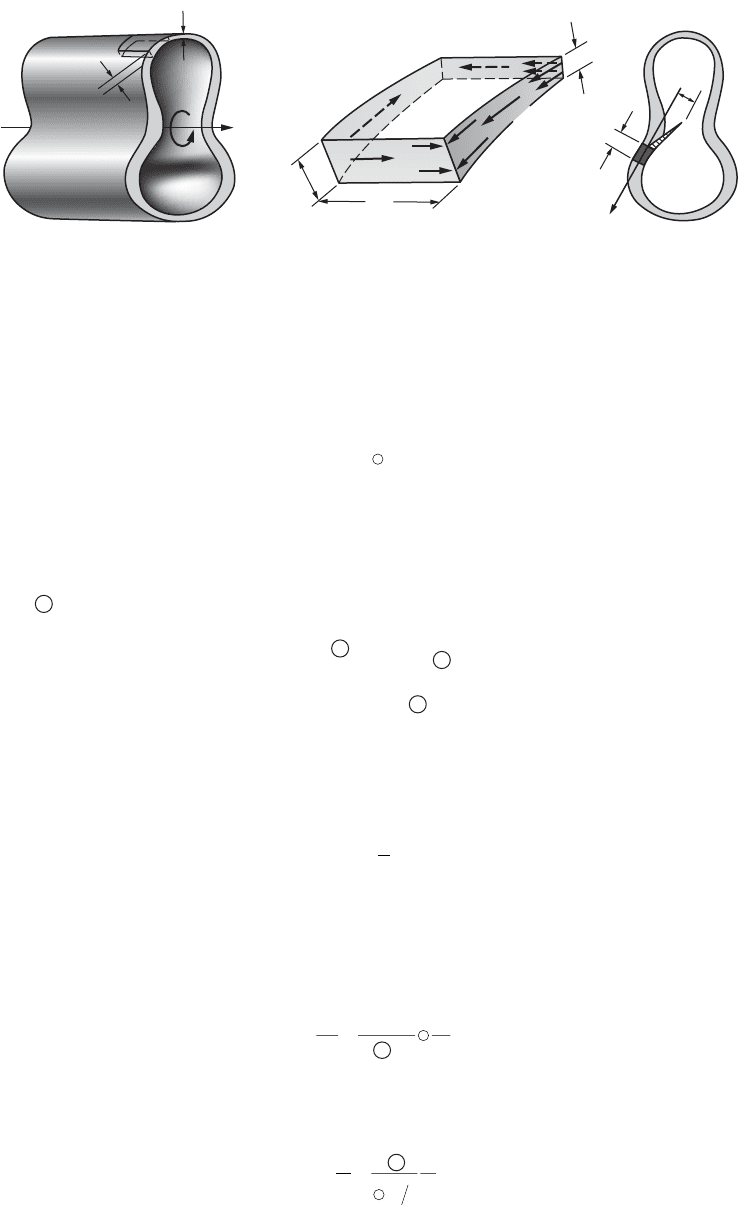
consider a tube of an arbitrary shape with varying wall thickness, such as shown in Fig. 46.20(a), subjected
to torque T. Isolate an element from this tube, as shown enlarged in Fig. 46.20(b). This element must be
in equilibrium under the action of forces F
1
, F
2
, F
3
, and F
4
. These forces are equal to the shear stresses
acting on the cut planes multiplied by the respective areas. From summation of forces, and since the
longitudinal sections were taken an arbitrary distance apart, it follows that the product of the shear stress
and the wall thickness is the same, i.e., constant, on any such planes. This constant will be denoted by
q, which is measured in the units of force per unit distance along the perimeter, since shear stresses on
mutually perpendicular planes are equal at a corner of an element. Hence, at a corner such as A in
Fig. 46.20(b), t
2
= t
3
; similarly, t
1
= t
4
. Therefore, t
4
t
1
= t
3
t
2
, or, in general, q is constant in the plane of
a section perpendicular to the axis of a member. The quantity q has been termed the shear flow. Next
consider the cross section of the tube as shown in Fig. 46.20(c). The force per unit distance of the
FIGURE 46.19 Cross-sectional warpage due to applied torque.
(a)
f
e
a
b
T
T
c
A
d
a
a
(b)
f
e
a
M
M
b
© 2003 by CRC Press LLC
Mechanics of Materials 46-21
perimeter of this tube, by virtue of the previous argument, is constant and is the shear flow q. This shear
flow multiplied by the length ds of the perimeter gives a force q ds per differential length. The product
of this infinitesimal force q ds and r around some convenient point such as 0, Fig. 46.20(c), gives the
contribution of an element to the resistance of applied torque T. Adding or integrating this,
(46.38)
where the integration process is carried around the tube along the center line of the perimeter. A simple
interpretation of the integral is available. It can be seen from Fig. 46.20(c) that rds is twice the value of
the shaded area of an infinitesimal triangle of altitude r and base ds. Hence, the complete integral is twice
the whole area bounded by the center line of the perimeter of the tube. Defining this area by the special
symbol , one obtains
T = 2 q or q = (46.39)
This equation applies only to thin-walled tubes. The area is approximately an average of the two areas
enclosed by the inside and the outside surfaces of a tube, or, as noted, it is an area enclosed by the center
line of the wall’s contour. It is not applicable at all if the tube is slit.
Since for any tube the shear flow q is constant, from the definition of shear flow, the shear stress at
any point of a tube where the wall thickness is t is
(46.40)
In the elastic range, Eqs. (46.39) and (46.40) are applicable to any shape of tube. For inelastic behavior,
Eq. (46.40) applies only if thickness t is constant. For linearly elastic materials, the angle of twist for a hollow
tube can be found by applying the principle of conservation of energy. Equating the elastic strain energy
to the external work per unit length of member, the following governing differential equation is obtained,
(46.41)
It is useful to recast this equation to express the torsional stiffness k
t
for a thin-walled hollow tube. Since
for a prismatic tube subjected to a constant torque, f = qL,
(46.42)
FIGURE 46.20 Thin-walled tubular member of variable thickness.
(a) (b) (c)
x
dx
T
t
2
t
2
t
1
t
3
t
4
t
1
F
2
r
ds
ds
O
q
F
3
F
4
A
t
2
F
1
Tqrds=
Ú
A
A
T
2 A
-------
A
t=
q
t
q
f
==
Ú
d
dx
T
AG
ds
t4
2
k
T
A
ds t
G
L
t
==
Ú
f
4
2
© 2003 by CRC Press LLC
46-22 The Civil Engineering Handbook, Second Edition
46.6 Bending
The Basic Kinematic Assumption
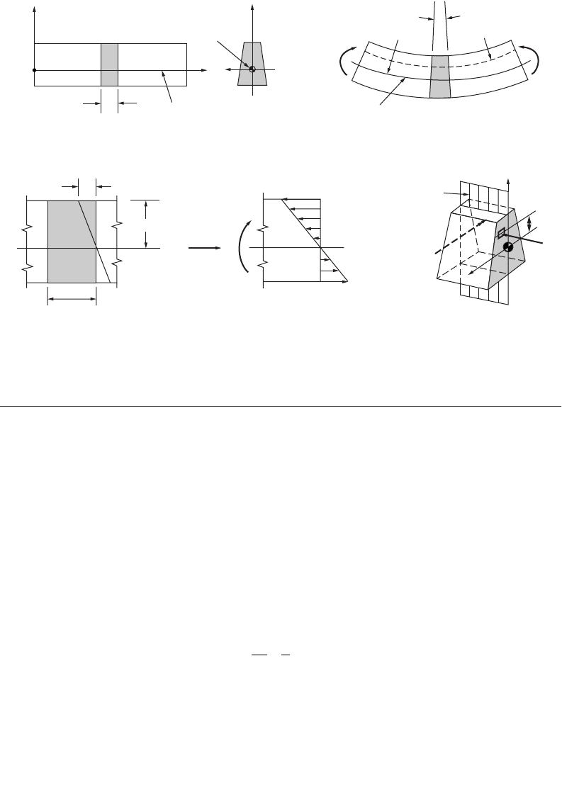
Consider a typical element of the beam between two planes perpendicular to the beam axis, as shown
in Fig. 46.21. In side view, such an element is identified in the figure as abcd. When such a beam is
subjected to equal end moments M
z
acting around the z axis, Fig. 46.21(b), this beam bends in the plane
of symmetry, and the planes initially perpendicular to the beam axis tilt slightly. Nevertheless, the lines
such as ad and bc becoming a¢d¢ and b ¢c ¢ remain straight. This observation forms the basis for the
fundamental hypothesis of the flexure theory. It may be stated thus: plane sections through a beam taken
normal to its axis remain plane after the beam is subjected to bending.
In pure bending of a prismatic beam, the beam axis deforms into a part of a circle of radius r, as
shown by Fig. 46.21(b). For an element defined by an infinitesimal angle dq, the fiber length ef of the
beam axis is given as ds = rdq. Hence,
(46.43)
where the reciprocal of r defines the axis curvature k.
The fiber length gh located on a radius (r – y) can be found similarly, and the difference between fiber
lengths gh and ef can be expressed as (–ydq), which is equal to du, since the deflection and rotations of
the beam axis are very small. Then one obtains the normal strain e
x
= du/dx, as
(46.44)
This equation establishes the expression for the basic kinematic hypothesis for the flexure theory: the
strain in a bent beam varies along the beam depth linearly with y.
FIGURE 46.21 Assumed behavior of elastic beam in bending.
(a)
(c) (d) (e)
(b)
y
y
y
y
ab
dc
O
A
dx
O
A
x
z
z
Beam axis
Bent axis
Centroid
Unit length
| e
max
|
| y |
max
=
c
s
max
s
x
s =
E
e
M
z
M
z
M
z
M
z
Plane of
symmetry
g
h
e
f
d
q
r
r
-
y
a
¢
b
¢
d
¢
c
¢
d
ds
q
r
k==
1
ek
x
y=-
© 2003 by CRC Press LLC

Mechanics of Materials 46-23
The Elastic Flexure Formula
By using Hooke’s law, the expression for the normal strain given by Eq. (46.44) can be recast into a
relation for the normal longitudinal stress:
(46.45)
To satisfy equilibrium, the sum of all forces at a section in pure bending must vanish,
which can be rewritten as
By definition, the integral
where
–
y is the distance from the origin to the centroid of an area A. Since the integral equals zero here
and area A is not zero, distance
–
y must be set equal to zero. Therefore, the z axis must pass through the
centroid of a section. In bending theory, this axis is also referred to as the neutral axis of a beam. On
this axis both the normal strain e
x
and the normal stress s
x
are zero. Based on this result, linear variation
in strain is schematically shown in Fig. 46.21(c). The corresponding elastic stress distribution in accor-
dance with Eq. (46.45) is shown in Fig. 46.21(d). Both the absolute maximum strain e
max
and the absolute
maximum stress s
max
occur at the largest value of y.
Equilibrium requires the additional condition that the sum of the externally applied and the internal
resisting moments must vanish. For the beam segment in Fig. 46.21(d), this yields
In mechanics, the last integral, depending only on the geometrical properties of a cross-sectional area,
is called the rectangular moment of inertia or the second moment of inertia of the area A and is designated
by I. Since I must always be determined with respect to a particular axis, it is often meaningful to identify
it with a subscript corresponding to such an axis. For the case considered, this subscript is z, that is,
(46.46)
With this notation, the basic relation giving the curvature of an elastic beam subjected to a specified
moment is expressed as
(46.47)
se k
xx
EEy==-
s
x
A
dA
Ú
= 0
-=
Ú
E ydA
A
k 0
ydA yA
A
Ú
=
MEydA
z
A
=
Ú
k
2
IydA
z
A
=
Ú
2
k=
M
EI
z
z
© 2003 by CRC Press LLC
46-24 The Civil Engineering Handbook, Second Edition
By substituting Eq. (46.47) into Eq. (46.45), the elastic flexure formula for beams is obtained:
(46.48)
It is customary to recast the flexure formula to give the maximum normal stress s
max
directly and to
designate the value |y|
max
by c, as in Fig. 46.21(c). It is also common practice to dispense with the sign,
as in Eq. (46.48), as well as with the subscripts on M and I. Since the normal stresses must develop a
couple statically equivalent to the internal bending moment, their sense can be determined by inspection.
On this basis, the flexure formula becomes
(46.49)
Elastic Strain Energy in Pure Bending
Using the section “Elastic Strain Energy for Uniaxial Stress” as the basis, the elastic strain energy for
beams in pure bending can be found. By substituting the flexure formula into Eq. (46.18) and integrating
over the volume, V, of the beam, the expression for the elastic strain energy, U, in a beam in pure bending
is obtained:
(46.50)
Unsymmetric Bending and Bending with Axial Loads
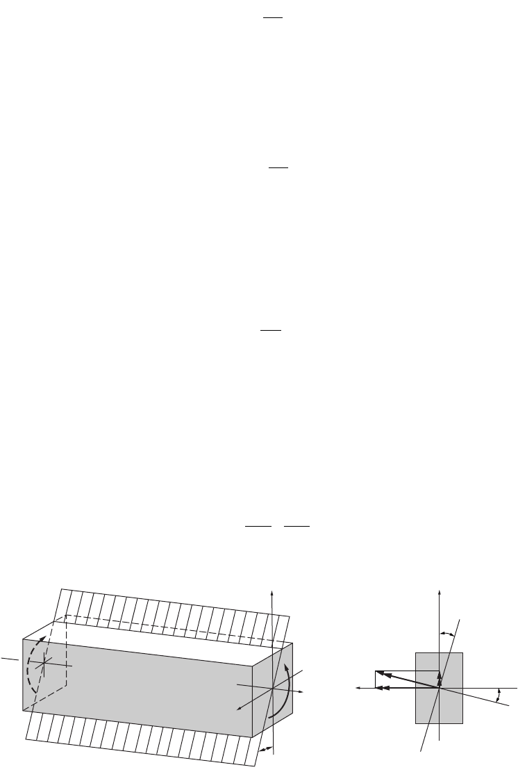
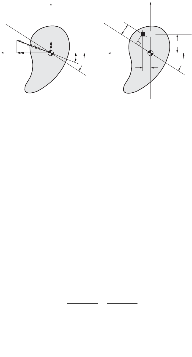
Consider the rectangular beam shown in Fig. 46.22, where the applied moments M act in the plane abcd.
By using the vector representation for M shown in Fig. 46.22(b), this vector forms an angle a with the
z axis and can be resolved into the two components, M
y
and M
z
. Since the cross section for this beam
has symmetry about both axes, Eqs. (46.45) to (46.49) are directly applicable. By assuming elastic behavior
of the material, a superposition of the stresses caused by M
y
and M
z
is the solution to the problem. Hence,
using Eq. (46.48),
(46.51)
FIGURE 46.22 Unsymmetrical bending of a beam with doubly symmetric cross section.
s
x
z
z
M
I
y=-
s
max
=
Mc
I
U
M
EI
dx
L
=
Ú
2
0
2
s
x
z
z
y
y
My
I
Mz
I
=- +
b
y
y
M
M
a
d
d
c
c
x
z
z
M
z
M
y
a
a
a
© 2003 by CRC Press LLC
Mechanics of Materials 46-25
A line of zero stress, i.e., a neutral axis, forms at an angle with the z axis and can be determined from
the following equation:
(46.52)
In general, the neutral axis does not coincide with the normal of the plane in which the applied moment
acts.
Superposition can again be employed to include the effect of axial loads, leading Eq. (46.51) to be
generalized into
(46.53)
where P is taken positive for axial tensile forces and bending takes place around the two principal y and
z axes. Further, if an applied axial force causes compression, a member must be stocky, lest a buckling
problem of the type considered in a later section arises.
Bending of Beams with Unsymmetric Cross Section
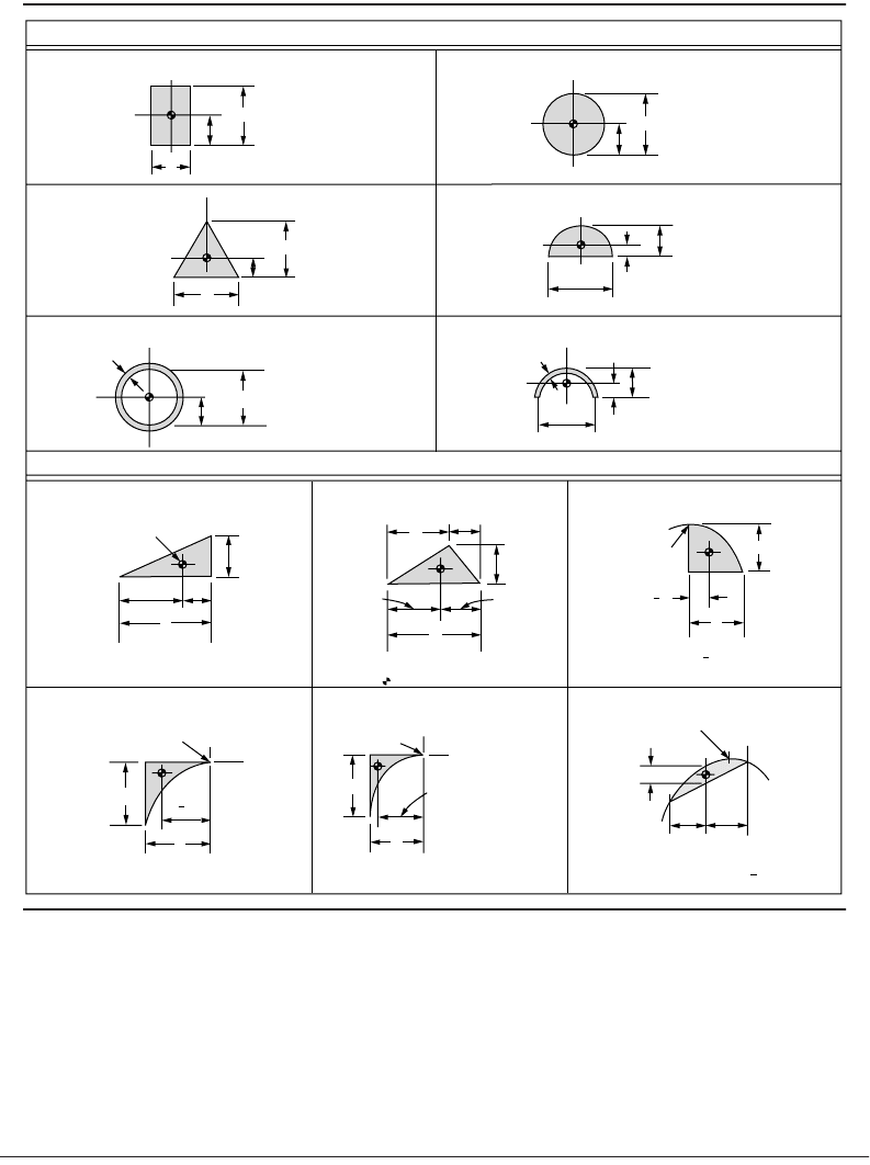
A general equation for pure bending of elastic members of an arbitrary cross section (Fig. 46.23), whose
reference axes are not the principal axes, can be formulated using the same approach as for the symmet-
rical cross sections. This generalized flexure formula is
(46.54)
By setting this equation equal to zero, the angle b for locating the neutral axis in the arbitrary coordinate
system is obtained, giving
(46.55)
FIGURE 46.23 Bending of unsymmetric cross section.
M
dA
C
C
a
b
b
M
z
M
y
y
y
y
z
z
z
r
NA NA
(a) (b)
tan tanba=
I
I
z
y
s
x
z
z
y
y
P
A
My
I
Mz
I
=- +
s
x
zy yyz
yz yz
yz zyz
yz yz
MI MI
II I
y
MI MI
II I
z=-
+
-
+
+
-
22
tanb= =
+
+
y
z
MI MI
MI MI
yz zyz
zy yyz
© 2003 by CRC Press LLC

46-26 The Civil Engineering Handbook, Second Edition
Area Moments of Inertia
The concept of moments of inertia is generalized here for two orthogonal axes for any cross-sectional
shape (Fig. 46.24). With the yz coordinates chosen as shown, by definition, the moments and product
of inertia of an area are given as
(46.56)
Note that these axes are chosen to pass through the centroid C of the area, and the product of the inertia
vanishes for either doubly or singly symmetric areas.
If the orthogonal axes are rotated by q, forming a new set of y ¢z ¢ coordinates, it can be shown that
the moments and product of inertia are transformed to the following quantities:
(46.57)
Note that the sum of the moments of inertia around two mutually perpendicular axes is invariant, that
is, I
y ¢
+ I
z ¢
= I
y
+ I
z
.
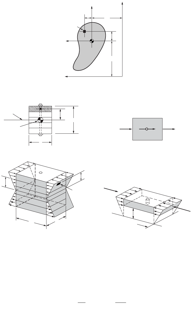
Table 46.3 provides formulas for the areas, centroids, and moments of inertia of some simple shapes.
Most cross-sectional areas used may be divided into a combination of these simple shapes. To find I for
an area composed of several simple shapes, the parallel-axis theorem (sometimes called the transfer
formula) is necessary. It can be stated as follows: the moment of inertia of an area around any axis is
equal to the moment of inertia of the same area around a parallel axis passing through the area’s centroid,
plus the product of the same area and the square of the distance between the two axes. Hence,
(46.58a)
FIGURE 46.24 Rotation of coordinate axes.
y
R
S
q
q
q
N
P
C
z
z'
Q
dA
y'
IydAIzdAIyzdA
zyyz
== =
ÚÚÚ
22
I
II II
I
I
II II
I
I
II
I
z
zy zy
yz
y
zy zy
yz
zy
zy
yz
¢
¢
¢¢
=
+
+
-
+
=
+
-
-
-
=-
-
+
22
22
22
22
2
22
cos sin
cos sin
sin cos
qq
qq
qq
II Ad
zzc z
=+
2
© 2003 by CRC Press LLC
Mechanics of Materials 46-27
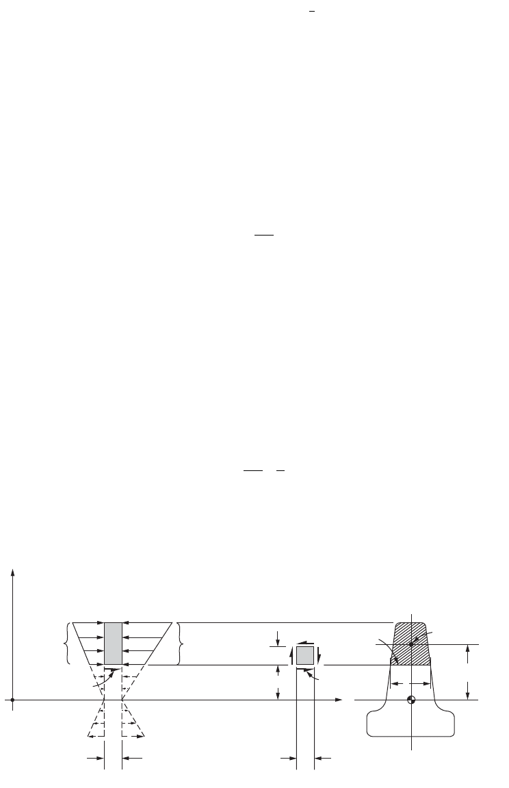
where d
z
is the distance from the centroid of the subarea to the centroid of the whole area, as shown in
Fig. 46.25. In calculation, Eq. (46.58a) must be applied to each subarea for which a cross-sectional area
has been divided and the results summed to obtain I
z
for the whole section:
(46.58b)
46.7 Shear Stresses in Beams
Shear Flow
Consider an elastic beam made from several continuous longitudinal planks whose cross section is shown
in Fig. 46.26. To make this beam act as an integral member, it is assumed that the planks are fastened at
intervals by vertical bolts. If an element of this beam, Fig. 46.26(b), is subjected to a bending moment
TA BLE 46.3 Some Properties of Areas
RECTANGLE
CIRCLE
SEMICIRCLE
HALF OF THIN TUBE
PARABOLA
TRIANGLE
PARABOLA
TRIANGLE
THIN TUBE
TRIANGLE
PARABOLA:
y
= −
ax
2
Areas and Centroids of areas
0
0
0
0
0
0
0
0
00
0
0
h
/2
h
b
A
=
bh
I
o
=
bh
3
/12
R
d
A
=
π
R
2
I
o
=
J
/2 = π
R
4
/4
2
R
4
R
/(3π)
R
A
=
π
R
2
/2
I
o
= 0.110R
4
t
2
R
av
b
h
h
/3
I
o
=
bh
3
/36
A
=
bh
/2
(2/π)
R
av
R
av
A
=
π
R
av
t
I
o
≈
0.095π
R
3
av
t
Vertex
3
8
b
b
h
A
=
2
3
bh
Vertex
h
l
/2
l
/2
The area for any segment
of a parabola is
A
=
2
3
hl
t
R
av
d
av
A
=
2π
R
av
t
I
o
=
J
/
2
≈
π
R
3
t
av
Centroid
h
b
b
/3
2b
/3
A
=
bh
/2
a
b
L
h
(
b
+
L
)/3(
a
+
L
)/3
A = hL
/2
Vertex
h
b
b
3
4
A
=
bh
/3
y
= −
ax
n
Vertex
h
b
A
=
bh
/(
n
+
1)
[(
n
+ 1)/(
n
+ 2)]
b
Areas and moments of inertia of areas around centroidal axes
IIAd
zzcz
whole section
()
=+
()
Â
2
© 2003 by CRC Press LLC
46-28 The Civil Engineering Handbook, Second Edition
+M
A
at end A and +M
B
at end B, bending stresses that act normal to the sections are developed. These
bending stresses vary linearly from the neutral axis in accordance with the flexure formula My/I. The
top plank of the beam element is isolated, as shown in Fig. 46.26(c). The forces acting perpendicular to
the ends A and B of this plank may be determined by summing the bending stresses over their respective
areas. Denoting the total force acting normal to the area fghj by F
B
, and remembering that, at section B,
M
B
and I are constants, one obtains the following relation:
(46.59)
FIGURE 46.25 Area for deriving the parallel-axis theorem.
FIGURE 46.26 Elements for deriving shear flow in a beam.
0
z
d
z
y
c
d
y
y
c
z
c
dA
z
c
y
C
Neutral axis
Centroid
(a)
b
p
n
k
h
g
m
h
y
−
j
f
(d)
A
R
B
F
A
jb
a
h
F
B
Neutral axis
(c)(b)
B
h
a
A
b
e
j
f
d
F
A
y
1
F
B
dA
y
B
A
dx
b
y
1
g
F
M
I
ydA
MQ
I
B
B
area fghj
B
=- =-
=
Ú
© 2003 by CRC Press LLC
Mechanics of Materials 46-29
where
(46.60)
The integral defining Q is the first, or statical, moment of area fghj around the neutral axis. By definition, y
is the distance from the neutral axis to the centroid of A
fghi
. Similarly, one can express the total force acting
normal to the area abcd as F
A
= –M
A
Q/I. If M
A
is not equal to M
B
, which is always the case when shears are
present at the adjoining sections, F
A
is not equal to F
B
. Equilibrium of the horizontal forces in Fig. 46.26(c)
may be attained only by developing a horizontal resisting force in the bolt R, as in Fig. 46.26(d). Taking a
differential beam element of length dx, M
B
= M
A
+ dM and dF = |F
B
| – |F
A
|, and substituting these relations
into the expression for F
A
and F
B
found above, one obtains dF = dM Q/I. It is more significant to obtain
the force per unit length of beam length, dF/dx, which will be designated by q and referred to as the shear
flow. Then, noting that dM/dx = V, one obtains the following expression for the shear flow in beams:
(46.61)
In this equation, I is the moment of inertia of the entire cross-sectional area around the neutral axis,
and Q extends only over the cross-sectional area of the beam to one side, at which q is investigated.
Shear-Stress Formula for Beams
The shear-stress formula for beams may be obtained by modifying the shear flow formula. In a solid beam,
the force resisting dF may be developed only in the plane of the longitudinal cut taken parallel to the axis
of the beam, as shown in Fig. 46.27. Therefore, assuming that the shear stress t is uniformly distributed
across the section of width t, the shear stress in the longitudinal plane may be obtained by dividing dF by
the area t dx. This yields the horizontal shear stress t, which for an infinitesimal element is numerically
equal to the shear stress acting on the vertical plane (see Fig. 46.27(b)). Since q = dF/dx, one obtains
(46.62)
where t is the width of the imaginary longitudinal cut, which is usually equal to the thickness or width
of the member. The shear stress at different longitudinal cuts through the beam assumes different values
as the values of Q and t for such sections differ.
FIGURE 46.27 Derivation of shear stress in a beam.
QydAAy
area fghj
fghj
==
=
Ú
q
VQ
I
=
t= =
VQ
It
q
t
Centroid of
fghj
y
A
B
dF
=
q dx
dx
F
A
F
B
=
F
A
+
dF
dy
x
dx
f
t
g
h
j
t
t
y
1
NA
Cross section
(c)(b)
(a)
Imaginary cut
y
−
© 2003 by CRC Press LLC
