Wai-Fah Chen.The Civil Engineering Handbook
Подождите немного. Документ загружается.

46-30 The Civil Engineering Handbook, Second Edition
Since the shear-stress formula for beams is based on the flexure formula, all the limitations imposed
on the flexure formula apply. The material is assumed to be elastic with the same elastic modulus in
tension as in compression. The theory developed applies only to straight beams. Moreover, in certain
cases such as a wide flange section, the shear-stress formula may not satisfy the requirement of a stress-
free boundary condition. However, no appreciable error is involved by using Eq. (46.62) for thin-walled
members, and the majority of beams belong to this group.
Shear Stresses in a Rectangular Beam
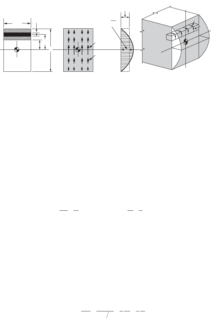
The cross-sectional area of a rectangular beam is shown in Fig. 46.28(a). A longitudinal cut through the
beam at a distance y
1
from the neutral axis isolates the partial area fghj of the cross section. Here t = b
and the infinitesimal area of the cross section may be conveniently expressed as b dy. By applying
Eq. (46.62), the horizontal shear stress is found at level y
1
of the beam. At the same cut, numerically
equal vertical shear stresses act in the plane of the cross section (t
xy
= t
yx
):
(46.63)
This equation shows that in a beam of rectangular cross section, both the horizontal and the vertical
shear stresses vary parabolically. The maximum value of the shear stress is obtained when y
1
is equal to
zero. In the plane of the cross section, Fig. 46.28(b), this is diagrammatically represented by t
max
at the
neutral axis of the beam. At increasing distances from the neutral axis, the shear stresses gradually
diminish. At the upper and lower boundaries of the beam, the shear stresses cease to exist as y
1
= ±h/2.
These values of the shear stresses at the various levels of the beam may be represented by the parabola
shown in Fig. 46.28(c). An isometric view of the beam with horizontal and vertical shear stresses is shown
in Fig. 46.28(d).
The maximum shear stress in a rectangular beam occurs at the neutral axis, and for this case, the
general expression for t
max
may be simplified by setting y
1
= 0.
(46.64)
where V is the total shear and A is the entire cross-sectional area. Since beams of rectangular cross-
sectional area are used frequently in practice, this equation is very useful. It is widely used in the design
of wooden beams, since the shear strength of wood on planes parallel to the grain is small. Thus, although
equal shear stresses exist on mutually perpendicular planes, wooden beams have a tendency to split
FIGURE 46.28 Shear stresses in a rectangular beam.
t
t
t
av
=
V
A
−
t
max
=
3
V
2
A
t
max
NA
t
dy
t
=
b
j
f
g
h
y
h
y
1
(a) (b) (c) (d)
t= = = =
Ê
Ë
Á
ˆ
¯
˜
-
È
Î
Í
Í
˘
˚
˙
˙
ÚÚ
VQ
It
V
It
ydA bydy
V
I
h
c
y
area
fghj
y
h
1
2
2
1
2
2
/
t
max
== = =
Vh
I
Vh
bh
V
bh
V
A
22
3
8812
3
2
3
2
© 2003 by CRC Press LLC
Mechanics of Materials 46-31
longitudinally along the neutral axis. Note that the maximum shear stress is 1½ times as great as the
average shear stress V/A. Nevertheless, in the analysis of bolts and rivets, it is customary to determine
their shear strengths by dividing the shear force V by the cross-sectional area A. Such practice is considered
justified since the allowable and ultimate strengths are initially determined in this manner from tests.
Warpage of Plane Sections Due to Shear
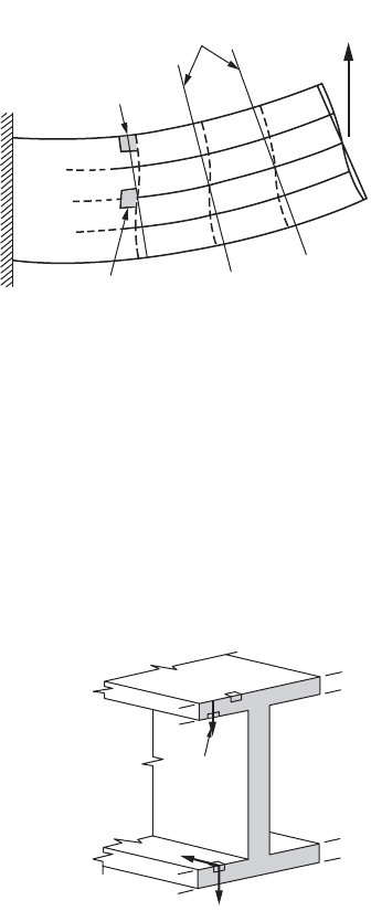
A solution based on the mathematical theory of elasticity
for a rectangular beam subjected simultaneously to
bending and shear shows that plane sections perpendic-
ular to the beam axis warp, i.e., they do not remain plane.
This can also be concluded from Eq. (46.63). According
to Hooke’s law, shear strains must be associated with
shear stresses. Therefore, the shear stresses given by
Eq. (46.63) give rise to shear strains. According to this
equation, the maximum shear stress, hence, maximum
shear strain, occurs at y = 0; conversely, no shear strain
takes place at y = ±h/2. This behavior warps the initially
plane sections through a beam, as shown qualitatively in
Fig. 46.29, and contradicts the fundamental assumption
of the simplified bending theory for pure flexure. How-
ever, based on rigorous analysis, warpage of the sections
is known to be important only for very short members
and is negligibly small for slender members. An examination of analytical results, as well as experimental
measurements on beams, suggests that the assumption of “plane sections” is reasonable. It should also
be noted that if shear force V along a beam is constant and the boundaries provide no restraint, the
warping of all cross sections is the same. Therefore, the strain distribution caused by bending remains
the same as in pure bending. Based on these considerations, a far-reaching conclusion can be made that
the presence of shear at a section does not invalidate the expressions for bending stresses derived earlier.
Shear Stresses in Beam Flanges
The shear-stress formula for beams is based on the flexure formula.
Hence, all of the limitations imposed on the flexure formula apply.
The material is assumed to be elastic with the same elastic modulus
in tension as in compression. The theory developed applies only
to straight beams. Moreover, there are additional limitations that
are not present in the flexure formula.
Consider a section through the I beam shown in Fig. 46.30. The
shear stresses computed for level 1-1 apply to the infinitesimal
element a. The vertical shear stress is zero for this element. Like-
wise, no shear stresses exist on the top plane of the beam. This is
as it should be, since the top surface of the beam is a free surface.
In mathematical phraseology, this means that the conditions at
the boundary are satisfied. For beams of rectangular cross section,
the situation at the boundaries is correct. A different condition is
found when the shear stresses determined for the I beam at level 2-2 are scrutinized. The shear stresses
were found to be 570 psi for the elements, such as b or c shown in the figure. This requires matching
horizontal shear stresses on the inner surfaces of the flanges. However, the latter surfaces must be free
of the shear stresses because they are free boundaries of the beam. This leads to a contradiction that
cannot be resolved by the methods of engineering mechanics of solids. The more advanced techniques
FIGURE 46.29 Shear distortions in a beam.
Maximum
distortion at
neutral axis
No
distortion
Plane
sections
P
FIGURE 46.30 Boundary conditions
are not satisfied at level 2-2.
1
2
2
1
2
2
1
1
570 psi
570 psi
b
a
c
© 2003 by CRC Press LLC
46-32 The Civil Engineering Handbook, Second Edition
of the mathematical theory of elasticity or three-dimensional finite-element analysis must be used to
obtain an accurate solution.
Fortunately, the above defect of the shear-stress formula for beams is not serious. The vertical shear
stresses in the flanges are small. The large shear stresses occur in the web and, for all practical purposes,
are correctly given by Eq. (46.62). No appreciable error is involved by using the relations derived in this
section for thin-walled members, and the majority of beams belong to this group. Moreover, as stated
earlier, the solution for the shear stresses of a beam with a rectangular cross section is correct.
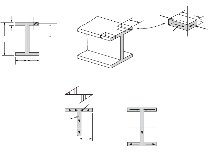
In an I beam, the shear stresses acting in a vertical longitudinal cut, as c-c in Fig. 46.31(a), act
perpendicular to the plane of the paper. Their magnitude may be found by applying Eq. (46.62), and
their sense follows by considering the bending moments at the adjoining sections through the beam. For
example, if for the beam shown in Fig. 46.31(b) positive bending moments increase toward the reader,
larger normal forces act on the near section. For the elements shown, tt dx or q dx must aid the smaller
force acting on the partial area of the cross section. This fixes the sense of the shear stresses in the
longitudinal cuts. However, numerically equal shear stresses act on the mutually perpendicular planes
of an infinitesimal element, and the shear stresses on such planes either meet or part with their directional
arrowheads at a corner. Hence, the sense of the shear stresses in the plane of the section also becomes
known.
The magnitude of the shear stresses varies for the different vertical cuts. For example, if cut c-c in
Fig. 46.31(a) is at the edge of the beam, the hatched area of the beam’s cross section is zero. However, if
the thickness of the flange is constant, and cut c-c is made progressively closer to the web, this area
increases from zero at a linear rate. Moreover, as y remains constant for any such area, Q also increases
linearly from zero toward the web. Therefore, since V and I are constant at any section through the beam,
shear flow q
c
= VQ/I follows the same variation. If the thickness of the flange remains the same, the shear
stress t
c
= VQ/It varies similarly. The same variation of q
c
and t
c
applies on both sides of the axis of
symmetry of the cross section. However, as may be seen from Fig. 46.31(b), these quantities in the plane
of the cross section act in opposite directions on the two sides. The variation of these shear stresses or
FIGURE 46.31 Shear forces in the flanges of an I beam.
F
+
dF
y
−
≈
h
/
2
b
/
2b
/
2
c
a
c
a
t
h
c
c
dx
F
dx
t
t dx
c
c
t
b
/
2
F
1
F
1
F
1
F
1
V
q
c
- max
2
q
c
- max
t
c
- max
or
q
c
- max
(c)
(d)
(b)
(a)
© 2003 by CRC Press LLC
Mechanics of Materials 46-33
shear flows is represented in Fig. 46.31(c), where for simplicity, it is assumed that the web has zero
thickness.
In common with all stresses, the shear stresses shown in Fig. 46.31(c), when integrated over the area
on which they act, are equivalent to a force. The magnitude of the horizontal force F
1
for one half of the
flange, Fig. 46.31(d), is equal to the average shear stress multiplied by one half of the whole area of the
flange, i.e.,
(46.65)
If an I beam transmits a vertical shear, these horizontal forces act in the upper and lower flanges. However,
because of the symmetry of the cross section, these equal forces occur in pairs and oppose each other,
and cause no apparent external effect.
To determine the shear flow at the juncture of the flange and the web, cut a-a in Fig. 46.31(a), the
whole area of the flange times y must be used in computing the value of Q. However, since in finding
q
c-max
, one half the flange area times the same y has already been used, the sum of the two horizontal
shear flows coming in from opposite sides gives the vertical shear flow at cut a-a. Hence, figuratively
speaking, the horizontal shear flows “turn through 90° and merge to become the vertical shear flow.”
Thus, the shear flows at the various horizontal cuts through the web may be determined in the manner
explained in the preceding sections. Moreover, the resistance to the vertical shear V in thin-walled I beams
is developed mainly in the web, as shown in Fig. 46.31(d). The sense of the shear stresses and shear flows
in the web coincides with the direction of the shear V. Note that the vertical shear flow “splits” upon
reaching the lower flange. This is represented in Fig. 46.31(d) by the two forces F
1
that are the result of
the horizontal shear flows in the flanges.
The shear forces that act at a section of an I beam are shown in Fig. 46.31(d), and for equilibrium,
the applied vertical forces must act through the centroid of the cross-sectional area to be coincident with
V. If the forces are so applied, no torsion of the member will occur. This is true for all sections having
cross-sectional areas with an axis of symmetry. To avoid torsion of such members, the applied forces
must act in the plane of symmetry of the cross section and the axis of the beam. A beam with an
unsymmetrical section will be discussed next.
Shear Center
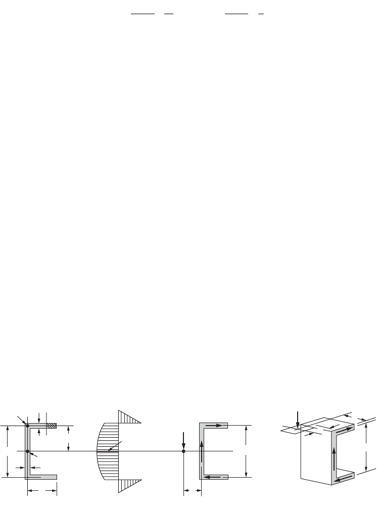
The channel section shown in Fig. 46.32 does not have a vertical axis of symmetry. Thus with bending
around the horizontal axis, there is a tendency for the channel to twist around some longitudinal axis.
To prevent twisting and thus maintain the applicability of the flexure formula, the externally applied
force P shown in Fig. 46.32(c) must be applied in such a manner as to balance the internal couple F
1
h.
This location is called the shear center or center of twist and is designated by the letter S. The shear center
for any cross section lies on a longitudinal line parallel to the axis of the beam. Any transverse force
FIGURE 46.32 Deriving location of shear center for a channel.
F
bt
F
q
b
cc
11
22 22
=
Ê
Ë
Á
ˆ
¯
˜
Ê
Ë
Á
ˆ
¯
˜
=
Ê
Ë
Á
ˆ
¯
˜
Ê
Ë
Á
ˆ
¯
˜
--
t
max max
or
P
e
V
L
h
F
1
F
1
F
1
F
1
h
e
V
=
P
P
S
t
a
or
q
a
t
a
t
f
or
q
f
t
c
c
a
f
t
b
h
-
y
(a) (b)
(c) (d)
© 2003 by CRC Press LLC
46-34 The Civil Engineering Handbook, Second Edition
applied through the shear center causes no torsion of the beam. For a channel section, the shear center
location measured by e from the center of the web is equal to b
2
h
2
t/4I. For a symmetrical angle, the shear
center is located at the intersection of the centerlines of its legs.
46.8 Transformation of Stress and Strain
Transformation of Stress
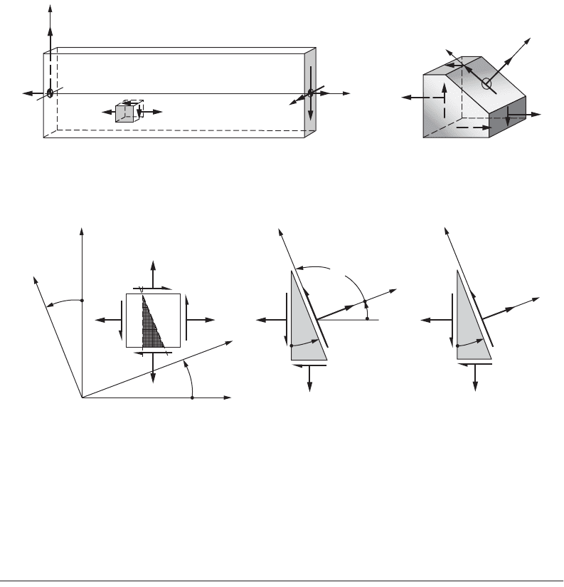
In stress analysis, a more general problem often arises, as illustrated in Fig. 46.33, in which element A is
subjected to a normal stress s
x
, due to axial pull and bending, and simultaneously experiences a direct
shear stress t
xy
. The combined normal stress with the shear stress requires a consideration of stresses on
an inclined plane, such as shown by Fig. 46.33(b). Since an inclined plane may be chosen arbitrarily, the
state of stress at a point can be described in an infinite number of ways, all of which are equivalent. The
planes on which the normal or shear stresses reach their maximum intensity have a particularly significant
effect on materials.
An infinitesimal element of unit thickness, as shown in Fig. 46.34(a), is used to describe the state of
two-dimensional stress. To determine stresses on any inclined plane, the fundamental procedure involves
isolating a wedge and using the equations of the equilibrium of forces. By multiplying the stresses shown
in Fig. 46.34(b) by their respective areas, a diagram with the forces acting on the wedge is constructed,
as in Fig. 46.34(c). Then, by applying the equations of static equilibrium to the forces acting on the
wedge, the stresses s
x¢
, s
y ¢
, and t
x¢y ¢
are obtained:
FIGURE 46.33 State of stress at a point on different planes.
FIGURE 46.34 Derivation of stress transformation on an inclined plane.
s
x
P
1
P
2
y
A
s
x
M
P
V
x
s
x
A
x
′
s
x
′
t
xy
t
yx
t
x
′
y
′
y
′
(a) (b)
y
′
x
′
y
+q
s
x
s
y
+q
s
x
s
x
t
xy
t
yx
s
y
x
′
t
xy
A
B
C
E
x
s
y
t
xy
A
B
C
D
s
x
′
q
q
90
o
t
x
′
y
′
q
s
x
dA
cosq
t
xy
dA
cosq
AB
C
t
y
dA
sinq
t
xy
dA
sinq
s
x
′
dA
t
x
′
y
′
dA
(a)
(b)
(c)
y
′
x
′
y
′
© 2003 by CRC Press LLC

Mechanics of Materials 46-35
(46.66)
(46.67)
(46.68)
These equations are the equations of transformation of stress from one set of coordinates to another.
The sign conventions assumed for positive stress and positive angle are depicted in Fig. 46.34(a).
By adding Eqs. (46.66) and (46.67), s
x¢
+ s
y¢
= s
x
+ s
y
, meaning that the sum of the normal stresses
on any two mutually perpendicular planes remain the same, that is, invariant, regardless of the angle q.
Principal Stresses
Interest often centers on the determination of the largest possible stress, as given by Eqs. (46.66) to
(46.68), and the planes on which such stresses occur. To find the plane for a maximum or a minimum
normal stress, Eq. (46.66) is differentiated with respect to q and the derivative is set equal to zero. Hence,
(46.69)
where the subscript of the angle is used to designate the angle that defines the plane of the maximum
or minimum normal stress. If the location of planes on which no shear stresses act is wanted, Eq. (46.68)
must be set equal to zero. This yields the same relation as that in Eq. (46.69). Therefore, an important
conclusion is reached: on planes on which maximum or minimum normal stresses occur there are no
shear stresses. These planes are called the principal planes of stress, and the stresses acting on these
planes — the maximum and minimum normal stresses — are called the principal stresses.
Equation (46.69) has two roots that are 90°
apart. One of these roots locates a plane on which the
maximum normal stress acts; the other root locates the corresponding plane for the minimum normal
stress. The magnitude of the principal stresses is obtained by substituting the values of the double angle
given by Eq. (46.69) into Eq. (46.66). The expression for the maximum normal stress (denoted by s
1
)
and the minimum normal stress (denoted by II
s
) becomes
(46.70)
where the positive sign in front of the square root must be used to obtain s
1
and the negative sign to
obtain s
2
.
Maximum Shear Stress
Similarly, to locate the planes on which the maximum or the minimum shear stresses act, Eq. (46.68)
must be differentiated with respect to and the derivative set equal to zero. Hence,
(46.71)
s
ss ss
qt q
¢
=
+
+
-
+
x
xy xy
xy
22
22cos sin
s
ss ss
qt q
¢
=
+
-
-
-
y
xy zy
xy
22
22cos sin
t
ss
qt q
¢¢
=-
-
+
xy
xy
xy
2
22sin cos
tan2
2
1
q
t
ss
=
-
()
xy
xy
s
ss ss
t
1
2
2
22
or 2
=
+
±
-
Ê
Ë
Á
ˆ
¯
˜
+
xy xy
xy
tan2
2
2
q
ss
t
=-
-
()
xy
xy
© 2003 by CRC Press LLC
46-36 The Civil Engineering Handbook, Second Edition
where the subscript 2 designates the plane on which the shear stress is a maximum or minimum. Again,
the two planes defined by this equation are mutually perpendicular. Moreover, Eq. (46.71) is a negative
reciprocal of Eq. (46.69). This means that the angles that locate the planes of maximum or minimum
shear stress form angles of 45° with the planes of principal stresses. A substitution of the results of
Eq. (46.71) into Eq. (46.68) gives the maximum and the minimum values of the shear stresses:
(46.72)
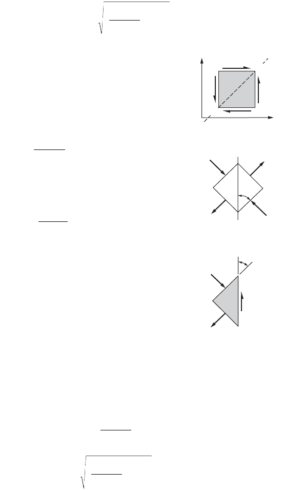
Thus, the maximum shear stress differs from the minimum shear
stress only in sign. From the physical point of view, these signs have
no meaning, and for this reason, the largest shear stress regardless of
sign will often be called the maximum shear stress. By substituting q
2
into Eq. (46.66), the normal stresses s¢ that act on the planes of the
maximum shear stresses are
(46.73)
If s
x
and s
y
in Eq. (46.73) are the principal stresses, t
xy
is zero and
Eq. (46.72) simplifies to
(46.74)
For pure shear, with the absence of normal stresses, the principal stresses
are numerically equal to the shear stress, as displayed by Fig. 46.35.
Mohr’s Circle of Stress
The equations of stress transformation given by Eqs. (46.66), (46.67),
and (46.68) may be presented graphically. They can be shown to
represent a circle written in parametric form,
(46.75)
where the center of the circle C is at (a, 0) and the circle radius is
equal to b:
(46.76)
(46.77)
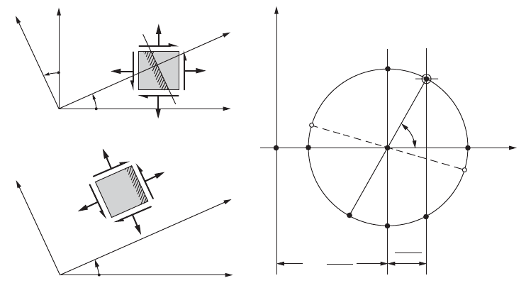
In a given problem, s
x
, s
y
, and t
xy
are the three known stresses of the element. Hence, if a circle satisfying
Eq. (46.75) is plotted, as shown in Fig. 46.36, the simultaneous values of a point (x, y) on this circle
correspond to s
x¢
and t
x¢y¢
for a particular orientation of an inclined plane. The circle so constructed is
called the circle of stress or Mohr’s circle of stress.
t
ss
t
max or min
=±
-
Ê
Ë
Á
ˆ
¯
˜
+
xy
xy
2
2
2
FIGURE 46.35 Equivalent repre-
sentations for pure shear stress.
s
2
= | t
xy
|
s
1
= | t
xy
|
y
| t
xy
|
| t
xy
|
t
xy
45°
45°
(b)
(c)
D
F
x
D
F
t
xy
(a)
¢
=
+
s
ss
xy
2
t
ss
max
=
-
12
2
st
¢¢¢
-
()
+=
xxy
ab
2
22
a
xy
=
+ss
2
b
xy
xy
=
-
Ê
Ë
Á
ˆ
¯
˜
+
ss
t
2
2
2
Mechanics of Materials 46-37
The coordinates for point A on the circle correspond to the stresses in Fig. 46.36(a) on the right face
of the element. The coordinates for the conjugate point B correspond to the stresses on the upper face
of the element. For any other orientation q of an element, such as shown in Fig. 46.36(b), a pair of
conjugate points J and K can always be found on the circle to give the corresponding stresses, as in
Fig. 46.36(c). This may be easily accomplished by rotating the AB axis by a corresponding 2q. The
following important observations regarding the state of stress at a point can be made based on the Mohr’s
circle:
1. The largest possible normal stress is s
1
, and the smallest is s
2
. No shear stresses exist with these
principal stresses.
2. The largest shear stress t
max
is numerically equal to the radius of the circle. A normal stress equal
to (s
1
+ s
2
)/2 acts on each of the planes of maximum shear stress.
3. If s
1
= s
2
, Mohr’s circle degenerates into a point, and no shear stresses develop in the xy plane.
4. If s
x
+ s
y
= 0, the center of Mohr’s circle coincides with the origin of the s – t coordinates, and
the state of pure shear exists.
5. The sum of the normal stresses on any two mutually perpendicular planes is invariant, that is,
s
x
+ s
y
= s
1
+ s
2
= s
x¢
+ s
y ¢
= constant.
Principal Stresses for a General State of Stress
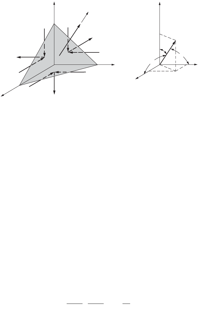
Consider a general state of stress and define an infinitesimal tetrahedron, as shown in Fig. 46.37. The
unknown stresses are sought on an arbitrary oblique plane ABC in the three-dimensional xyz coordinate
system. A set of known stresses on the other three faces of the mutually perpendicular planes of the
tetrahedron is given. These stresses are the same as those shown earlier in Fig. 46.2. A unit normal n to
the oblique plane defines its orientation. This unit vector is identified by its direction cosines l, m, and
n, as illustrated by Fig. 46.37(b). Further, if the infinitesimal area ABC is defined as dA, then the three
areas of the tetrahedron along the coordinate axes are dA l, dA m, and dA n. Force equilibrium for the
tetrahedron can now be written by multiplying the stresses given in Fig. 46.37 by the respective areas
established. It will be assumed that only a normal stress s
n
(i.e., a principal stress) is acting on face ABC;
then a system of linear homogeneous equations is obtained that has nontrivial solution if and only if the
determinant of the coefficients of l, m, and n vanishes. Expansion of this determinant gives
FIGURE 46.36 Mohr’s circle of stress.
y
′
J
(s
x
′
, t
x
′
y
′
)
q
q
q
(a)
(b) (c)
y
+s
x
+s
y
x
′
+t
xy
x
+s
y
′
+s
x
′
+t
x
′
y
′
K
O
t
max
A
(s
x
,
t
xy
)
C
D
2q
1
s
2
s
s
1
t
s
x
− s
y
2
s
x
+ s
y
2
t
min
B
(s
y
′
−t
xy
)
a
=
y
′
x
′
x
© 2003 by CRC Press LLC
46-38 The Civil Engineering Handbook, Second Edition
(46.78)
where
The constants I
s
, II
s
, and III
s
are invariant, since if the initial coordinate system is changed, thereby
changing the three mutually perpendicular planes of the tetrahedron, the s
n
on the inclined plane must
remain the same. In general, Eq. (46.78) has three real roots. These roots are the eigenvalues of the
determinant and are the principal stresses of the problem.
Transformation of Strain
The transformation of normal and shear strain from one set of rotated axes to another (Fig. 46.38) is
completely analogous to the transformation of normal and shear stresses presented earlier.
Fundamentally, this is because both stresses and strains are second-rank tensors and mathematically
obey the same laws of transformation. One may then obtain equations of strain transformation from
the equations of stress transformation by simply substituting the normal stress s with the normal strain
e and the shear stress t with shear strain g. Hence, the basic expressions for strain transformation in a
plane in an arbitrary direction defined by the x¢ axis are
(46.79)
(46.80)
The sign convention adopted corresponds to the element distortions shown in Fig. 46.38(a) for positive
strain. Likewise, Mohr’s circle of strain can be constructed where every point on the circle gives two
values: one for the normal strain, and the other for the shear strain divided by 2.
FIGURE 46.37 Tetrahedron for deriving a principal stress on an oblique plane.
(a)
(b)
A
O
z
B
z
x
y
y
Unit
vector
n
n
m
a
b
l
a
g
C
x
t
xz
s
z
s
n
t
yz
t
xy
s
x
t
xz
t
yz
s
y
t
yx
= t
xy
ss s
ss snn n
IIIIII
32
0-+ -=
I
II
III
xyz
xy yz zx xy yz zx
xyz xyyzxz xyz y xz z xy
s
s
s
sss
ss ss ss t t t
sss t t t st st st
=++
=++
()
-++
()
=+ -++
222
222
2
e
ee ee
q
g
q
¢
=
+
+
-
+
x
xy xy xy
22
2
2
2cos sin
geeqgq
¢¢
=- -
()
+
xy x y xy
sin cos22
© 2003 by CRC Press LLC
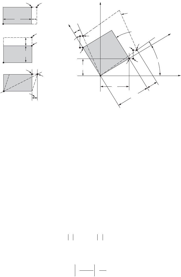
Mechanics of Materials 46-39
Yield and Fracture Criteria
Thus far the idealized mathematical procedures for determining the states of stress and strain, as well as
their transformation to different coordinates, have been presented. However, it must be pointed out that
the precise response of real materials to such stresses and strains defies accurate formulations. As yet, no
comprehensive theory can provide accurate predictions of material behavior under the multitude of
static, dynamic, impact, and cyclic loading, as well as temperature effects. Only the classical idealizations
of yield and fracture criteria for materials are discussed in this section.
The maximum shear-stress theory, or simply the maximum shear theory, results from the observation
that in a ductile material slip occurs during yielding along critically oriented planes. This suggests that the
maximum shear stress plays the key role, and it is assumed that yielding of the material depends only on
the maximum shear stress that is attained within an element. Therefore, whenever a certain critical value
s
n
is reached, yielding in an element commences. For a given material, this value usually is set equal to
the shear stress at yield s
yp
in simple tension or compression. Hence, according to Eq. (46.72), t
max
=
t
cr
= s
yp
/2. In applying this criterion to a biaxial plane stress problem, two different cases arise. In one
case, if the signs of the principal stresses
s
1
and s
2
are the same, the maximum shear stress is of the same
magnitude, as would occur in a simple uniaxial stress. Therefore, the criteria corresponding to this case are
(46.81)
In the second case, the signs of s
1
and s
2
are opposite, and the maximum shear stress t
max
= (|s
1
| + |s
2
|)/2.
Hence,
(46.82)
A plot of Eqs. (46.81) and (46.82) is shown in Fig. 46.39. If a point defined by s
2
/s
yp
and s
1
/s
yp
falls
on the hexagon shown, a material begins and continues to yield. No such stress points can lie outside
FIGURE 46.38 Exaggerated deformations of elements for deriving strains along new axes.
Deformed element
Original element
C
y
A
dx
x
dy
A
dx
dy
O
O
B
′
B
B
′′
B
′′′
A
′
A
′′
A
′′′
dx
′
a
q
b
y
′
e
x
′
dx
′
g
xy
dy
A
′′
A
′′′
e
y
dy
A
′
A
′′
e
x
dx
A
′
x
′
(b)(a)
O
O
ss ss
12
££
yp yp
and
±
-
£
ss
s
12
22
yp
© 2003 by CRC Press LLC
