Wai-Fah Chen.The Civil Engineering Handbook
Подождите немного. Документ загружается.

Physical Water and Wastewater Treatment Processes 9-19
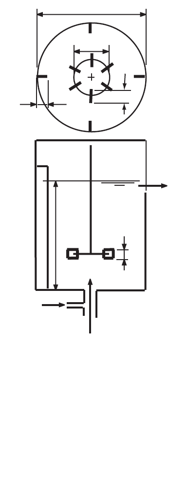
disc, as shown, or they may be curved or pitched at an angle to the disc. The number of blades varies,
but a common choice is six. Almost always, there are several baffles mounted along the tank wall to
prevent vortexing of the liquid. The number of baffles and their width are design choices, but most
commonly, there are four baffles.
The power dissipated by the turbulence in a tank is related to the geometry of the tank and mixer and
the rotational speed of the mixer. Dimensional analysis suggests an equation of the following form
(Rushton, Costich, and Everett, 1950):
(9.42)
where d
i
= the impeller diameter (m or ft)
d
t
= the tank diameter (m or ft)
Fr = the Froude number of the impeller (dimensionless)
= w
2
d
i
/g
g = the acceleration due to gravity (m/s
2
or ft/sec
2
)
h
l
= the depth of liquid in the tank (m or ft)
h
i
= the height of the impeller above the tank bottom (m or ft)
l
i
= the impeller blade length (m or ft)
FIGURE 9.3 Turbine definition sketch.
d
t
d
i
w
b
l
i
Q
h
l
w
i
coagulant
raw water, Q
Ru Re Fr=
()
fddhhlN Nnn pw w
itili b ibi i b i
,,,,,,, , , ,,, ,
© 2003 by CRC Press LLC
9-20 The Civil Engineering Handbook, Second Edition
N
b
= the baffle reference number, i.e., the number of baffles in some arbitrarily chosen “stan-
dard” tank (dimensionless)
n
b
= the number of baffles in the tank (dimensionless)
N
i
= the impeller reference number, i.e., the number of impeller blades on some arbitrarily
chosen “standard” impeller (dimensionless)
n
i
= the number of impeller blades (dimensionless)
P = the power dissipated by the turbulence (watts or ft·lbf/sec)
p
i
= the impeller blade pitch (m or ft)
Re = the impeller Reynolds number (dimensionless)
= wd
i
2
/n
Ru = the Rushton power number (dimensionless)
= P/rw
3
d
i
5
w
b
= the width of the baffles (m or ft)
w
i
= the impeller blade width (m or ft)
n = the kinematic viscosity of the liquid (m
2
/sec or ft
2
/sec)
r = the mass density of the liquid (kg/m
3
or slugs/ft
3
)
w = the rotational speed of the impeller (Hz, revolutions per sec)
The geometry of turbine/tank systems has been more or less standardized against the tank diameter
(Holland and Chapman, 1966; Tatterson, 1994):
(9.43)
(9.44)
(9.45)
(9.46)
(9.47)
(9.48)
(9.49)
Turbines usually have six blades, and tanks usually have four baffles extending from the tank bottom
to somewhat above the highest liquid operating level.
For any given tank, all the geometric ratios are constants, so the power number is a function of only
the Reynolds number and the Froude number. Numerous examples of such relationships are given by
Holland and Chapman (1966).
For impeller Reynolds numbers below 10, the hydraulic regime is laminar, and Eq. (9.42) is found
experimentally to be,
h
d
l
t
= 1
1
6
1
2
££
h
d
d
i
t
i
; usually
1
4
1
2
13££
d
d
i
t
; usually
1
6
1
4
15££
w
d
i
i
; usually
l
d
i
i
=
1
4
; for hub-mounted blades
l
d
i
i
=
1
8
; for disk-mounted blades
1
12
1
10
110££
w
d
b
t
; usually
© 2003 by CRC Press LLC

Physical Water and Wastewater Treatment Processes 9-21
(9.50)
The value of the constant is typically about 300, but it varies between 20 and 4000 (Tatterson, 1994).
Equation (9.50) indicates that the power dissipation is proportional to the viscosity, the square of the
impeller rotational speed and the cube of the impeller diameter:
(9.51)
For impeller Reynolds numbers above 10,000, the hydraulic regime is turbulent, and the experimental
relationship for baffled tanks is,
(9.52)
Typical values of the constant are (Tatterson, 1994):
•Hub-mounted flat blades, 4
•Disk-mounted flat blades, 5
• Pitched blades, 1.27
•Propellers, 0.6
The power number for any class of impeller varies significantly with the details of the design. Impeller
design and performance are discussed by Oldshue and Trussell (1991).
Equation (9.52) indicates that the power dissipation is proportional to the liquid density, the cube of
the impeller rotational speed, and the fifth power of the impeller diameter:
(9.53)
The typical turbine installation operates in the turbulent region. Operation in the transition region
between the laminar and turbulent zones is not recommended, because mass transfer rates in the
transition region tend to be lower and less predictable than in the other regions (Tatterson, 1994).
Paddle Wheel Flocculators
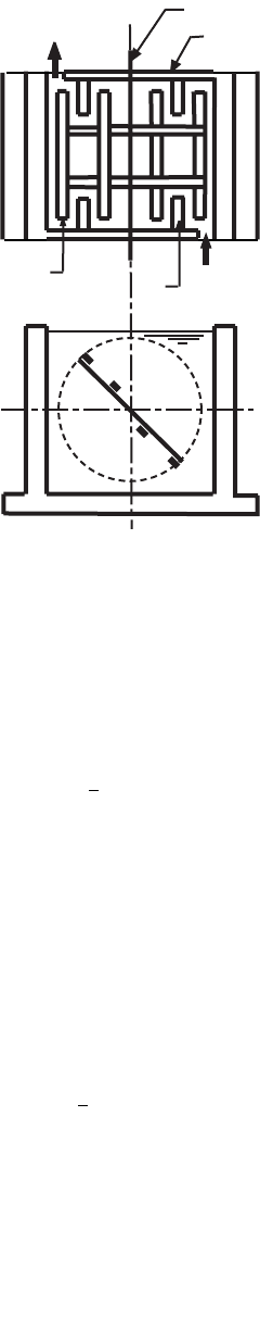
A typical flocculation tank compartment is depicted in Fig. 9.4. Paddle flocculators similar to this design,
but without the stators and baffles and with the axles transverse to the flow, were first introduced by
Smith (1932). A set of flocculation paddles is mounted on a drive axle, which runs along the length of
the compartment parallel to the flow. The axle may be continuous throughout the whole tank, or it may
serve only one or two compartments. Alternatively, the axle may be mounted vertically in the compart-
ment or horizontally but transverse to the flow. In these cases, each compartment has its own axle. The
paddles are mounted parallel to the drive axle. The number of paddles may be the same in each
compartment or may vary. The compartments in the flocculator are separated from each other by cross
walls called “baffles.” The baffles are not continuous across the tank; there are openings between the
baffles and tank walls so that water can flow from one compartment to the next. In Fig. 9.4, an opening
is shown at one end of each baffle, and the openings alternate from one side of the tank to the other, so
they do not line up. This arrangement minimizes short-circuiting. The spaces are sometimes put at the
top or bottom of the baffles so as to force an over-and-under flow pattern. The compartments also
contain stators. These are boards fixed to the baffle walls. They are intended to prevent the setup of a
vortex in the compartment.
Although flocculator performance is usually correlated with tank-average parameters like
—
G and HRT,
it should be remembered that the actual flocculation process occurs in the immediate vicinity of the
paddles and their structural supports. The flow around the paddles and supports is sensitive to their
exact geometry and their rotational speed. This means that precise prediction of flocculator performance
Re Ru◊ = a constant
Pd
i
µmw
23
Ru = a constant
Pd
i
µrw
35
© 2003 by CRC Press LLC
9-22 The Civil Engineering Handbook, Second Edition
requires the testing of full-scale units. Facilities may require redesign and reconstruction of the paddle
system in the light of operating experience. Some engineers will prefer to specify commercially available
paddle systems, which have demonstrated satisfactory performance on similar waters. Contracts with
vendors should include performance specifications and guarantees.
Paddle geometry can be connected to power input by Camp’s (1955) method. The drag force on the
paddle is given by:
(9.54)
where F
D
= the drag force on the paddle (N or lbf)
C
D
= the drag coefficient (dimensionless)
A = the area of the paddle normal to the direction of movement (m
2
or ft
2
)
n
p
= the velocity of the paddle relative to the tank (m/s or ft/sec)
n = the velocity of the water relative to the tank (m/s or ft/sec)
r = the density of the water (kg/m
3
or slug/ft
3
)
The power dissipated by the paddle is simply the drag force multiplied by the velocity of the paddle
relative to the tank (not relative to the water, as is often incorrectly stated):
(9.55)
where P
p
= the power dissipated by the paddle (W or ft·lb/sec).
Once steady state mixing is established, the water velocity will be some constant fraction of the paddle
velocity, i.e., v = kv
p
. The paddle speed is taken to be the speed of its centroid around the axle, which is
related to its radial distance from the axle. Making these substitutions yields:
(9.56)
FIGURE 9.4 Flocculation tank plan and cross section.
Stator
Paddle
Drive Axle
Baffle
wsl
Flow
Flow
FCAvv
DDp
=-
()
1
2
2
r
PCAvvv
pDpp
=-
()
1
2
2
r
PCkAr
pD
=-
()
41
3
2
33
pr w
© 2003 by CRC Press LLC

Physical Water and Wastewater Treatment Processes 9-23
where k = the ratio of the water velocity to the paddle velocity (dimensionless)
r = the radial distance of the centroid of the paddle to the axle (m or ft)
w = the rotational velocity of the paddle (revolutions/sec)
If the paddle is wide, the area should be weighted by the cube of its distance from the axle (Fair, Geyer,
and Okun, 1968).
(9.57)
where B = the width of the paddle (m or ft)
L = the length of the paddle (m or ft)
r
1
= the distance of the outer edge of the paddle from the axle (m or ft)
r
0
= the distance of the inner edge of the paddle from the axle (m or ft)
This refinement changes Eq. (9.56) to:
(9.58)
Equation (9.56) or Eq. (9.58) should be applied to each paddle and support in the tank, and the results
should be summed to obtain the total power dissipation:
(9.59)
(9.60)
Equations (9.59) and (9.60) provide the needed connection to the volume-averaged characteristic
strain rate:
(9.61)
It is generally recommended that the strain rate be tapering downwards from the inlet chamber to the
outlet chamber, say from 100/sec to 50/sec. The tapering of
—
G that is required can be achieved by reducing,
from inlet to outlet, either the rotational speed of the paddle assemblies or the paddle area.
Another criterion sometimes encountered is the “Bean Number” (Bean, 1953).
This is defined as the
volume swept out by the elements of the paddle assembly per unit time — called the “displacement” —
divided by the flow through the flocculation tank:
(9.62)
where Be = the Bean number (dimensionless).
Bean’s recommendation, based on a survey of actual plants, is that Be should be kept between 30 and
40, if it is calculated using all the paddle assemblies in the flocculation tank (Bean, 1953). For a given
facility, the Bean number is proportional to the spatially averaged characteristic strain rate and the total
water power. However, the ratio varies as the square of the rotational speed.
rA rLdB r r L
r
r
o
o
33
1
4
1
4
1
==-
()
Ú
PC krrL
pD o
=-
()
-
()
pr w
3
2
1
4
3
1
PC k Ar
Dii
i
n
=-
()
=
Â
41
3
2
33
1
pr w
PC k rrL
Dioii
i
n
=-
()
-
()
=
Â
pr w
3
2
3
1
4
1
1
,,
G
2
==
e
nm
P
V
Be =
=
Â
2
1
pw rA
Q
ii
i
n
© 2003 by CRC Press LLC

9-24 The Civil Engineering Handbook, Second Edition
The mixing conditions inside a tank compartment are usually turbulent, so the drag coefficient is a
constant.
Camp reports that the value of k for paddle flocculators with stators varies between 0.32 and 0.24 as
the rotational speed increases (Camp, 1955).
The peripheral speed of the paddle assembly is usually kept below 2 ft/sec, and speeds of less than
1 ft/sec are recommended for the final compartment (Bean, 1953; Hopkins and Bean, 1966). In older
plants, peripheral speeds were generally below 1.8 ft/sec (Bean, 1953). This practice appears to have been
based on laboratory data that was developed using 1 gal jars without stators. The laboratory data indicated
impaired flocculation at peripheral speeds above 1.8 ft/sec, but the results may have been caused by
vortexing, which would actually reduce the velocity gradients in the liquid (Leipold, 1934).
Paddles are usually between 4 and 8 in. wide, and the spacing between paddles should be greater than
this (Bean, 1953). The total paddle area should be less than 25% of the plan area of the compartment.
Jets
The power expended by a jet is simply the kinetic energy of the mass of liquid injected into the tank:
(9.63)
where
•
m is the mass flow rate in the jet at its inlet (kg/s or slug/sec). The mass flow rate is determined
by the mixing requirements.
Static In-Line Mixers
The energy dissipated by static mixers is determined by the pressure drop through the unit:
(9.64)
where Dp = the pressure drop (N/m
2
or lbf/ft
2
)
Q = the volumetric flow rate (m
3
/s or ft
3
/sec).
The pressure drop depends on the details of the mixer design.
Gas Sparging
The power dissipated by gas bubbles is,
(9.65)
where g = the acceleration due to gravity (9.80665 m/s
2
or 32.174 ft/sec
2
)
H = the depth of bubble injection (m or ft)
Q = the gas flow rate (m
3
/s or ft
3
/sec)
r = the liquid density (kg/m
3
or slug/ft
3
)
Blending
The principal purpose of all mixing is blending two or more different liquid streams.
Batch Mixing Times
The time required to blend two or more liquids to some acceptable level of macroscopic homogeneity
is determined by batch blending tests. The test results are usually reported in terms of a homogenization
number that is defined to be the number of impeller revolutions required to achieve homogenization
(Tatterson, 1994):
(9.66)
Pmv=
1
2
2
˙
PQ p= ◊ D
P gQH=r
Ho =wt
m
© 2003 by CRC Press LLC
Physical Water and Wastewater Treatment Processes 9-25
where Ho = the homogenization number (dimensionless)
t
m
= the blending time (sec)
w = the rotational speed of the impeller (Hz, revolutions per sec)
The degree of mixing is often determined from tracer data by calculating the “fractional unmixedness,”
which is defined in terms of measured concentration fluctuations (Godfrey and Amirtharajah, 1991;
Tatterson, 1994):
(9.67)
where C
0
= the initial tracer concentration the tank, if any, prior to tracer addition and mixing (kg/m
3
or lb/ft
3
)
C
t
= the maximum tracer concentration at any point in the tank at time t (kg/m
3
or lb/ft
3
)
C
•
= the calculated tracer concentration for perfect mixing (kg/m
3
or lb/ft
3
)
X
t
= the fractional unmixedness (dimensionless)
Blending is considered to be complete when X
t
falls to 0.05, meaning that the observed concentration
fluctuations are within 5% of the perfectly mixed condition.
Tu rbines
The Prochazka-Landau correlation (Tatterson, 1994) for a turbine with six flat, disk-mounted blades in
a baffled tank is,
(9.68)
For a turbine with four pitched blades, their correlation is,
(9.69)
And for a three-bladed marine propeller, it is,
(9.70)
where d
i
= the impeller diameter (m or ft)
d
t
= the tank diameter (m or ft)
X
0
= the initial fractional unmixedness, typically between 2 and 3 in the cited report (dimensionless)
X
f
= the final fractional unmixedness, typically 0.05
t
m
= the required batch mixing time (sec)
w = the impeller rotational speed (Hz, revolutions per sec)
Note that impeller diameter is more important than impeller speed, because the mixing time is inversely
proportional to the impeller diameter raised to a power greater than 2, whereas it is inversely proportional
to the speed to the first power.
Equations (9.68) through (9.70) demonstrate that for any particular design, the homogenization
number is a constant. The equations are best used to convert data from one impeller size to another.
X
CC
CC
t
t
o
=
-
-
•
•
wt
m
t
i
o
f
d
d
X
X
=
Ê
Ë
Á
ˆ
¯
˜
Ê
Ë
Á
ˆ
¯
˜
0 905
257
. log
.
wt
m
t
i
o
f
d
d
X
X
=
Ê
Ë
Á
ˆ
¯
˜
Ê
Ë
Á
ˆ
¯
˜
202
220
. log
.
wt
m
t
i
o
f
d
d
X
X
=
Ê
Ë
Á
ˆ
¯
˜
Ê
Ë
Á
ˆ
¯
˜
348
205
. log
.
© 2003 by CRC Press LLC

9-26 The Civil Engineering Handbook, Second Edition
The homogenization number is also a constant in the laminar region, but the constant is independent
of impeller size. Turbines are seldom used in laminar conditions, but propellers mounted in draft tubes
are. Reported homogenization numbers for propeller/tube mixers range from 16 to 130 (Tatterson, 1994).
Static In-Line Mixers
A wide variety of proprietary static in-line mixers is available. Some designs are specialized to laminar
or turbulent flow conditions, and other designs are general purpose mixers. Static mixers are liable to
clog with large suspended solids and require filtered or screened feed streams.
The usual specification is that the coefficient of variation of concentration measurements in the mixer
outlet be equal to less than 0.05 (Godfrey and Amirtharajah, 1991; Tatterson, 1994). Mixer unit lengths
are typically 5 to 50 times the pipe diameter, depending on the design.
The standard deviation of concentration measurements over any mixer cross section declines expo-
nentially with mixer length and may be correlated by (Godfrey and Amirtharajah, 1991),
(9.71)
where D = the mixer’s diameter
f = the mixer’s Darcy-Weisbach friction factor (dimensionless)
L = the mixer’s length (m or ft)
s = the standard deviation of the concentration measurements over the outlet cross section
(kg/m
3
or lb/ft
3
)
s
0
= the standard deviation of the concentration measurements over the inlet cross section
(kg/m
3
or lb/ft
3
)
Jets
Jet mixers have relatively high power requirements, but they are low-maintenance devices. They are
restricted to turbulent, medium- to low-viscosity liquid mixing, and the jet Reynolds number at the inlet
should be above 2100 (Tatterson, 1994). The required pump may be inside or outside the tank, depending
on equipment design.
Jets may enter the tank axially on the tank bottom or radially along the tank side. Axial entry can be
used for deep tanks in which the liquid depth to tank diameter ratio is between 0.75 and 3, and radial
entry can be used for shallow tanks in which the depth–diameter ratio is between 0.25 and 1.25 (Godfrey
and Amirtharajah, 1991). If the depth–diameter ratio exceeds 3, multiple jets are required at different
levels. Radial inlets are frequently angled upwards.
Mixing of the jet and surrounding fluid does not begin until the jet has traveled at least 10 inlet
diameters, and effective mixing occurs out to about 100 inlet diameters. Oldshue and Trussell (1991)
recommend that the tank diameter to jet inlet diameter ratio be between 50 and 500.
If the initial jet Reynolds number is 5000 or more, the batch mixing time is given by (Godfrey and
Amirtharajah, 1991),
(9.72)
For initial jet Reynold’s numbers below 5000, the mixing time is given by,
(9.73)
s
s
fL
D
o
=-
Ê
Ë
Á
ˆ
¯
˜
2
154
05
exp
.
.
t
mj
j
t
j
l
j
v
d
d
d
d
d
=
Ê
Ë
Á
ˆ
¯
˜
Ê
Ë
Á
ˆ
¯
˜
6
32 12
t
mj
j
t
j
l
j
v
d
d
d
d
d
=
Ê
Ë
Á
ˆ
¯
˜
Ê
Ë
Á
ˆ
¯
˜
30 000
Re
32 12
© 2003 by CRC Press LLC

Physical Water and Wastewater Treatment Processes 9-27
where d
j
= the jet’s inlet diameter (m or ft)
d
l
= the liquid depth (m or ft)
d
t
= the tank diameter (m or ft)
Re = the jet’s inlet Reynold’s number (dimensionless)
= n
j
d
j
/n
n
j
= the jet’s inlet velocity (m/s of ft/sec)
t
m
= the required mixing time (sec)
Other correlations are given by Tatterson (1994).
Continuous Flow
In order to account for their exponential residence time distributions, the required hydraulic retention
time in continuous flow tanks ranges from 50 to 200 times the batch mixing time, and is typically about
100 times t
m
(Tatterson, 1994):
(9.74)
Particle Suspension
Settleable Solids
Settleable solids are usually put into suspension using downwards-directed axial flow turbines, sometimes
with draft tubes. Tank bottoms should be dished, and the turbine should be placed relatively close to the
bottom, say between 1/6 and 1/4 of the tank diameter (Godfrey and Amirtharajah, 1991). Antivortex
baffles are required. Sloping side walls, bottom baffles, flat bottoms, radial flow turbines, and large tank
diameter to impeller diameter ratios should be avoided, as they permit solids accumulation on the tank
floor (Godfrey and Amirtharajah, 1991; Tatterson, 1994).
The impeller speed required for the suspension of settleable solids is given by the Zweitering (1958)
correlation:
(9.75)
where d
p
= the particle diameter (m or ft)
d
i
= the turbine diameter (m or ft)
g = the acceleration due to gravity (9.80665 m/s
2
or 32.174 ft/sec
2
)
S = the impeller/tank geometry factor (dimensionless)
X
p
= the weight fraction of solids in the suspension (dimensionless)
w
js
= the impeller rotational speed required to just suspend the particles (Hz, revolutions per sec)
r = the liquid density (kg/m
3
or slug/ft
3
)
r
p
= the particle density (kg/m
3
or slug/ft
3
)
Equation (9.75) is the “just suspended” criterion. Lower impeller speeds will allow solids to deposit
on the tank floor. The impeller/tank geometry factor varies significantly. Typical values for many different
configurations are given by Zweitering (1958).
The Zweitering correlation leads to a prediction for power scale-up that may not be correct. In the
standard geometry, the liquid depth, tank diameter, and impeller diameter are proportional. Combining
this geometry with the power correlation for the turbulent regime [Eq. (9.57)], one gets,
(9.76)
tt
hm
ª 100
w
n
rr
r
js
p
p
p
i
Sd
g
X
d
=
-
()
È
Î
Í
Í
˘
˚
˙
˙
01 02
045
013
085
..
.
.
.
P
V
d
dd
dd
dd
d
i
lt
ii
lt
t
µµ µ
-
-
w
35
2
255 5
2
055
.
.
© 2003 by CRC Press LLC

9-28 The Civil Engineering Handbook, Second Edition
Some manufactures prefer to scale power per unit volume as d
t
–0.28
and others prefer to keep the power
per unit volume constant.
If solids are to be distributed throughout the whole depth of the liquid, then the modified Froude
number must be greater than 20 (Tatterson, 1994):
(9.77)
The concentration profile can be estimated from (Tatterson, 1994):
(9.78)
(9.79)
where d
i
= the impeller’s diameter (m or ft)
d
l
= the total liquid depth (m or ft)
d
p
= the particle’s diameter (m or ft)
Pe = the solid’s Peclet number (dimensionless)
= n
ps
d
l
/d
p
n
p
= the particle’s free settling velocity in still liquid (m/s or ft/sec)
n
ps
= the particle’s free settling velocity in stirred liquid (m/s or ft/sec)
—
X
p
= the mean particle mass fraction in the tank (dimensionless)
X
p
(z) = the particle mass fraction at elevation z above the tank bottom (dimensionless)
z = the elevation above the tank bottom (m or ft)
e = the power per unit mass (W/kg or ft·lbf/slug·sec)
r = the density of the liquid (kg/m
3
or slug/ft
3
)
r
p
= the density of the particle (kg/m
3
or slug/ft
3
)
n = the kinematic viscosity (m
2
/s or ft
2
/sec)
w = the rotational speed of the impeller (Hz, revolutions per sec)
Floatable Solids
The submergence of low-density, floating solids requires the development of a vortex, so only one
antivortex baffle or narrow baffles (w
b
= d
t
/50) should be installed (Godfrey and Amirtharajah, 1991).
The axial flow turbine should be installed close to the tank bottom and perhaps off-center. The tank
bottom should be dished. The minimum Froude number for uniform mixing is given by,
(9.80)
where Fr
min
= the required minimum value of the Froude number (dimensionless)
Fr = the impeller Froude number (dimensionless)
= w
2
d
i
/g
Fr =
-
()
Ê
Ë
Á
ˆ
¯
˜
>
rw
rr
22
045
20
d
gd
d
d
i
pp
p
i
.
Xz
X
z
d
p
p
l
()
=
◊ -
◊
Ê
Ë
Á
ˆ
¯
˜
--
()
Pe
Pe
Pe
exp
exp1
Pe =
Ê
Ë
Á
ˆ
¯
˜
Ê
Ë
Á
ˆ
¯
˜
-
-
330
117
4
3
0 095
w
e
n
d
v
d
i
p
p
.
.
Fr
min
.
.
.=
Ê
Ë
Á
ˆ
¯
˜
-
Ê
Ë
Á
ˆ
¯
˜
-
0 036
365
042
d
d
i
t
p
rr
r
© 2003 by CRC Press LLC