Woodyard D. (ed.) Pounders Marine diesel engines and Gas Turbines
Подождите немного. Документ загружается.

The concept was already proven in the field, having been offered as an optional
feature for the larger ABB TPL-C turbochargers for a number of years.
The A100 turbocharger casings reflect the much higher mechanical
demands imposed on them. In designing the casings, ABB worked closely
with enginebuilders to secure the same compactness as the TPS units as well
as optimum mounting of the turbocharger on the engine console. The safety
of the containment concept—vital in view of the significantly increased power
density—was confirmed both numerically and experimentally on the test rig.
A stronger shaft (required because of the higher power transmission) was
also a factor in designing the A100 bearing assembly, which was based on
TPS turbocharger bearing technology. On the turbine side, the casing cen-
tring concept which had proved successful with the TPS-F turbocharger was
retained.
Three completely new compressor stages, each with different wheel blad-
ing, allow the compressor volume flow range of the TPS-F turbochargers to
be covered by the A100-M/H models with significantly higher pressure ratios.
New high-pressure diffusers and compressor blading were developed in addi-
tion to innovative wheel cooling to facilitate the full-load pressure ratios of
around 5.8 with a single-piece aluminium compressor wheel.
A range of compressor stages is available for every turbocharger frame
size, allowing optimum matching in every application. The compressor map
shows high efficiencies, excellent map widths and more than adequate over-
speed margins. An 80 per cent compressor efficiency is attained on a typical
generator line for a full-load pressure ratio of 5.8.
A new generation of mixed-flow turbines was developed for the A100 tur-
bochargers in addition to the existing TPS mixed-flow turbine stage. A char-
acteristic of the new turbine family is the larger operating range, allowing the
high pressure ratio potential of the new compressor stage to be exploited over
an even wider range of application. The turbine design is optimized in each
specific volume flow range so that the individual stages exhibit higher turbine
efficiencies than the current TPS turbine stages. Further development of the
sealing technologies has reduced the bypass flows so that flow losses are also
lower. In particular, this has allowed a substantial improvement in turbocharg-
ing performance at higher boost pressures.
ABB designed the A100-L programme for advanced two-stroke engine
generations planned or under development, taking special account of the mar-
ket’s increasing focus on reducing emissions. The A100-L series was headed
in 2008 by the A175-L model for boosting medium bore low-speed two-stroke
engines designed to benefit from compressor pressure ratios of up to 4.7 at the
highest turbocharger efficiencies. (ABB continues to supply its TPL-B family
for engines requiring pressure ratios of up to 4.2.)
New compressor stages with further optimized impeller blading, new dif-
fusers and new air casings are incorporated. Turbines and gas chambers are
also new, along with an integrated emergency lube oil tank originally devel-
oped for larger TPL-B turbochargers. VTG is available as an option.
a100 series 209
210 Pressure Charging
naPier TurBoChargers
UK-based Napier Turbochargers, which was acquired from the Siemens group
in 2008 by Primary Capital, offers its Napier 7-series and 8-series designs for
application to two- and four-stroke engines developing up to 10 500 kW per
turbocharger.
Based on the designer’s original cartridge construction, Napier 7-series tur-
bochargers are suitable for engines with outputs from 2000 kW to 6500 kW per
turbocharger. Developed from the company’s earlier generation, these NA297,
NA307, NA357 and NA397 models achieve pressure ratios of up to 5:1 and
an overall efficiency exceeding 70 per cent. Optimization for different applica-
tions and fuels is facilitated by alternative compressor options, and an innova-
tive lip seal secures effective turbine end sealing at all operating loads.
Cost and complexity is reduced by the air-cooled operation, while the car-
tridge construction enhances on-site maintenance and cuts downtime. Service
life is extended and through-life costs reduced by a squeeze film bearing
system.
Proven features from the 7-series, including cartridge construction and
lip seal turbine sealing, were retained for the new generation 8-series, whose
development was stimulated by the need to offer turbochargers capable of
yielding pressure ratios in excess of 5:1 and serving engines with outputs of
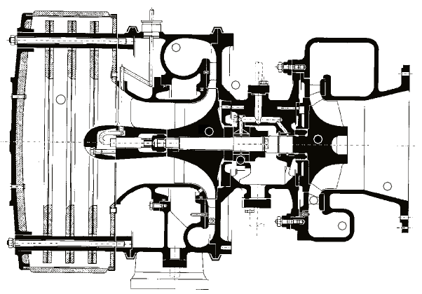
up to 10 500 kW per turbocharger. Exploiting aerodynamic and mechanical
advances, the new axial-turbine series (Figure 7.21) comprises NA298, NA358,
NA398 and NA498 models. A pressure ratio of 5.5:1 can be achieved in con-
tinuous operation with an overall efficiency of up to 70 per cent, while report-
edly maintaining a service life similar to the 7-series products.
Enhanced levels of component durability are also claimed, while the air-
cooled design contributes to a reduced overall weight. Inboard bearings were
Figure 7.21 Cross-section of napier 458 turbocharger for medium-speed engines
applied for the first time on a Napier turbocharger of this size, the hydrody-
namic units securing stable rotor dynamic performance and underwriting a long
life. The new bearing arrangement facilitates the use of axial and radial exhaust
gas flow into the turbocharger, extending the options for the enginebuilder.
Two separate compressor wheel designs are offered to provide differing
characteristics for optimized efficiency in diverse applications. Other features
include a circular exhaust flange (eliminating the need for transition pieces)
and a mounting flange incorporating both the lube oil inlet and outlet. Another
concept pioneered by Napier—cartridge construction—benefits serviceability
of the 7-series and 8-series, this configuration allowing operators to remove
and repair the rotor and bearings through a simple procedure without disturb-
ing the exhaust connections. Good access is also provided to key functional
areas such as the nozzle ring.
Titanium compressors, offering enhanced aerodynamic potential and
mechanical properties, were initially planned to replace the aluminium compo-
nents, but design refinements enabled the required performance to be attained
with aluminium.
Smaller engine requirements are addressed by the Napier 047, 057 and
067 all-radial air-cooled turbochargers in the 7-series, which are suitable for
engines developing outputs from 500 kW to around 1700 kW and yield pres-
sure ratios of up to 5. Typical applications include the Wärtsilä 20 engine and
other circa-200 mm bore genset engines. The 047 model features inboard bear-
ings and is uncooled. In common with other turbochargers in the series, the
bearings are designed to run on the engine’s lube oil system and to yield an
extremely long life, even when operating on contaminated lube oil. The 047
model incorporates 50 per cent fewer parts than its predecessor, the Napier
CO45. Cost savings result from using a reduced number of components, and
maintenance is simplified, with no special tooling required or clearances to set.
Simple clamps are used to hold the casings together and provide total index-
ability of connecting flange positions.
Earlier axial-flow turbine Napier 457 and 557 models, which serve engines
from 4000 kW to 10 000 kW output, featured long-life outboard plain hydrody-
namic bearings fed directly from the engine lube oil system and water-cooled
casings.
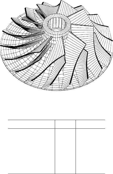
High efficiency at all pressure ratios was sought from the 5- and 7-series
through advanced compressor and turbine aerodynamic designs. The com-
pressor stage features a one-piece aluminium alloy wheel manufactured on
five-axes milling machines (Figure 7.22). Vanes with sweepback and rake are
specified to secure high performance, and a divergent circular arc (DCA) dif-
fuser design yields maximum pressure recovery from a compact configuration.
A high-efficiency fabricated nozzle with profiled blades serves the turbine sec-
tion of the small and large axial-flow turbochargers.
Napier turbochargers exploit the heavy fuel bearing design to secure a long
service life, even when operating with the poorest quality engine lubricating
oil: a bearing life exceeding 20 000 h is reportedly common.
napier turbochargers 211
212 Pressure Charging
napier turbocharger series performance data
7-Series 8-Series
Pressure ratio capability 5:1 5.5:1
eciency at 5:1 65% 70%
design point pressure
ratio
4:1 4.5:1
design point eciency 70% 75%
eciency at 2.5:1 65% 70%
Man diesel
A full range of turbochargers for two- and four-stroke engines is offered by
MAN Diesel of Germany, its PBS Turbo subsidiary in the Czech Republic and
overseas licensees. The current programme embraces the older NR/R series, the
NR/S series and the NA/S/T9 series, and the new generation TCR radial series
and TCA axial series; in addition, the PT/ PTG power turbine series is avail-
able for turbo compound systems.
na and nr series
The NA/S and NR/S series turbochargers were progressively introduced to the
market in the 1990s, their uncooled casings and inboard plain bearing features
subsequently being adopted by other turbocharger manufacturers.
The radial-flow turbine NR/S series was designed for safe control of the
charge air pressure ratio of up to 4.5, adequate extension of the application
Figure 7.22 a 3d Cad visualization of the napier 457 turbocharger impeller, show-
ing the one-piece intervaned swept-back design with tip rake
range, a higher efficiency level, improved reliability in all operating ranges,
unrestricted heavy fuel capability and reduced maintenance demands. Seven
models—the NR12/S, NR14/S, NR17/S, NR20/S, NR24/S, NR29/S and
NR34/S—formed the programme, which overlapped with the smallest of
the established axial-flow turbine NA/S series. The totally water-free series
(Figure 7.23) was a further development of the established NR/R turbo-
charger, featuring a revised compressor and turbine wheel. MAN Diesel’s
proven system of internal plain bearings was retained, the axial thrust now
being absorbed by a separate thrust bearing. The five models in the radial-flow
turbine NR/R series serve engine outputs from around 400 kW to 4400 kW
per turbocharger.
The development targets for the axial-flow turbine NA/S and NA/T9 series
turbochargers listed the following performance criteria:
l Medium-speed four-stroke engines: a compressor ratio in excess of 4,
and a turbocharger efficiency in excess of 60 per cent
l Low-speed two-stroke engines: a compressor ratio in excess of 3.6, a
turbocharger efficiency of at least 64 per cent (without an associated
power turbine system) and a turbocharger efficiency of at least 69 per
cent (with a power turbine system)
l A pressure ratio of up to 4.5 for the NA/S and 4 for the NA/T9
Man diesel 213
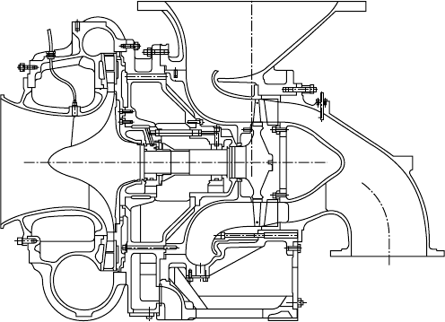
1 Turbine rotor with shaft
2 Compressor wheel
3 Bearing casing
4 Bearing bush
5 Gas inlet casing
6 Nozzle ring
7 Outlet diffuser
8 Compressor casing
9 Diffuser
10 Silencer
10
8
3
5
6
7
2
4
1
Figure 7.23 Man diesel nr/s radial-ow turbocharger
214 Pressure Charging
MAN Diesel carried out extensive theoretical and experimental investiga-
tions on the key individual turbocharger components: the compressor, turbine
and bearings. Apart from higher efficiencies from the turbine and compressor,
the goals included the attainment of high vibratory stability for the bladings
and a smooth running performance at low bearing temperatures.
A one-piece radial compressor wheel with continuously backswept blades
was selected to secure an uprated pressure ratio and flow rate, and improved
vibratory stability. The wheel carries 10 main blades and 10 splitter blades.
The introduction of splitter blades reportedly yielded a marked increase in effi-
ciency for pressure ratios 3.5, and an adequate safety margin against surging
in the part-load range was maintained. Various coatings, such as Keplacoat and
Alumite, have been investigated to protect the compressor wheels against cor-
rosive attack undermining the fatigue strength under reversed bending stresses.
A few percentage points improvement in efficiency was also gained by
the development of a new turbine blade and by optimizing the outlet diffuser.
The investment-cast turbine blade offers a significant cost reduction over a
forged blade, while retaining the material properties and the fatigue strength
under reversed bending stresses. The resistance of the blading to vibrations and
‘exceptionally smooth’ running at pressure ratios of up to 4.5 were promoted
by the incorporation of a floating bush in the turbine bearing system.
The S-type turbochargers are characterized by uncooled turbine casings
and bearing housings, dispensing with the previous double-walled heavy cas-
ings and cooling connections. The water-cooled bearing casing was retained,
however, for the NA/T9 turbocharger. Tests with an NA57/T9 turbocharger
serving a MAN B&W 6L60MC low-speed engine achieved an efficiency of
around 67.5 per cent at the 100 per cent load point; the charge air pressure
ratio was around 3.6. The maximum efficiency measured at near-70 per cent
engine load was around 69 per cent. A high efficiency level over the remaining
load range was also logged.
Axial-turbine NA series and radial-turbine NR series turbochargers are still
manufactured by MAN Diesel and its licensees to serve appropriate engines
that remain in production. The NA series now embraces six models cover-
ing maximum supercharged engine outputs per turbocharger from 3600 kW
to 24 500 kW. The seven-model NR series covers an engine power range from
670 kW to 5400 kW per turbocharger.
TCa series
In 1999/2000 MAN Diesel decided to develop a completely new turbocharger
generation to replace the NA series, resulting in the launch in 2002 of the TCA
series with radial-flow compressor wheel and axial-flow turbine blading. The
designers pursued the following goals: high specific flow rates, high efficien-
cies, low noise emissions, ease of maintenance and reduced servicing times,
ease of engine mounting and high reliability with a long service life.
The six-model TCA series addresses two- and four-stroke engines requir-
ing from around 3000 kW to 30 000 kW output per turbocharger. All elements
of the design were optimized with regard to flow control and stress reduction
using 3D CFD and FEM calculations.
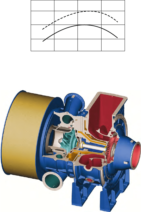
The TCA series was headed into production by the TCA77 model (Figure
7.24) with additional frame sizes from the TCA33 to the TCA99 planned to fol-
low progressively and cover the requirements of the highest powered two- and
four-stroke engines. The largest projected model was subsequently deemed
unnecessary, thanks to the performance of the TCA88-25 model, which can serve
two-stroke engines with 27 300 kW output per turbocharger (Figure 7.25).
Fewer turbochargers to boost a given low-speed engine are thus enabled.
An 8-cylinder MAN B&W K98MC/ME or MC-C/ME-C engine, for example,
can be specified with two TCA88-25 turbochargers instead of the previous out-
fit of three, and 12-cylinder engines of the same type can be boosted by three
such turbochargers instead of the previous four.
Man diesel 215
TCA77
NA57/TO10
1 2 3 4 5
Compressor pressure ratio
1.1
1.0
0.9
Reference efficiency
Figure 7.24 eciency map of the prototype Man diesel TCa77 turbocharger plot-
ted against the maximum eciency of the earlier na57 design
Figure 7.25 Man diesel’s axial-ow TCa series turbocharger
216 Pressure Charging
Most TCA models are available in three versions:
1. Two-stroke version—pressure ratio of up to 4.2, primarily for two-
stroke engines
2. Four-stroke version—pressure ratio of up to 4.7, for both four- and two-
stroke engines
3. High-pressure version—pressure ratio of up to 5.2, for future four-
stroke engines with very high mean effective pressures.
Increased efficiency was secured by newly developed wide-chord turbine
blades, which are very stiff and highly wear resistant, and supported in the tur-
bine disc with fir-tree feet. A damping wire thus became unnecessary, easing
maintenance work. Efficiency was also raised by a new optimized turbine out-
let diffuser and turbine inlet casing, while a new turbine nozzle ring extended
durability.
Running on two internal radial bearings with floating bushes and a sepa-
rate thrust bearing, the advanced rotor design achieves higher safety margins.
Bearing points with small diameters were realized by optimizing both the
rotor dynamics and the shaft/hub connection of the compressor wheel and
turbine shaft. The resulting low circumferential speeds of the bearing bushes
and minimization of friction losses contribute to a higher total efficiency. Very
quiet running and minimal bearing wear are cited for the floating journal bear-
ing bushes, which optimize damping behaviour, and the bearing body has an
expected service life of up to 50 000 h.
Mechanical losses are minimized by a reduced shaft diameter and high-
performance thrust bearings. Easy handling and short maintenance times were
sought from the support design; neither the compressor casing nor the turbine
rotor, for example, has to be disassembled when removing the thrust bearing.
Very high centrifugal forces result from a compressor wheel operating
at a circumferential speed of well over 500 m/s. A standard aluminium alloy
design and a specially adapted machining process ensure a long service life for
a component subjected to high-pressure conditions. An optimized geometry is
said to secure high efficiency at a safe surge margin over the whole operating
range, and noise is considerably reduced. A new type of force and form lock-
ing compressor wheel attachment on the turbine shaft enables assembly and
disassembly of the wheel without the need for an unwieldy hydraulic tool. The
new MAN Diesel-patented shaft/hub connection substantially reduces replace-
ment times and eases maintenance.
Efficiency is enhanced by the newly developed compressor volute and com-
pressor diffuser vanes, while optional internal recirculation (IRC) increases the
surge margin, and optional jet assistance provides fast rotor acceleration.
TCA nozzle rings are manufactured from high-resistance materials to
secure a long service life. Optimum matching of the turbocharger to the spe-
cific engine is smoothed by individually adapting nozzle rings. A new vari-
able turbine area (VTA) option, however—detailed in the section Variable
Turbine Area Technology—enables the flow cross-section to be adapted to the
corresponding load condition of the engine, thereby reducing fuel consumption
and emissions, especially in part-load operation.
Optimized mounting to the engines is facilitated by enabling all casings to
be installed and turned in 15° steps, and newly developed one- and two-socket
compressor spirals and diffusers foster optimum matching of the turbocharger
to the engine.
A modular design allows the turbocharger to cover as broad a range of
applications as possible. Air is sucked in either via an intake air silencer, a
90° intake casing or an intake manifold; exhaust gas flows into the turbine via
either an axial- or radial-flow casing. The design features the separate casing-
base concept proven in the NA series. The compressor volute is available with
either one or two opposing thrust pieces: the single-piece variant has advan-
tages for two- and four-stroke in-line cylinder engines, while the two-piece
volute offers advantages when attaching a single turbocharger to V-type four-
stroke engines.
Both the compressor wheel and the turbine can be adjusted to engine
requirements by choosing from a range of meridians and blading configura-
tions. Diffusers and nozzle rings that are very finely stepped in their mass-flow
areas allow the turbochargers to be fine-tuned to the engine. A nozzle ring
capable of adjustment during operation is available optionally for maximum
variability.
A minimal number of external connections were sought. On the engine side
and in the plant system itself the only additional connections—apart from the
air and exhaust gas connections—are an oil inlet and drain pipe, together with
a breather connection for the bracket. No cooling water, or lock-air connec-
tions, additional oil overflow piping or external lube oil supply are required. A
special emergency operation facility is integrated into the turbocharger to allow
continued operation under emergency conditions. All the hot casing compo-
nents are equipped with a new temperature- and noise-reducing casing with
a sheet metal cover, significantly reducing the risk of engineroom personnel
coming into contact with excessively hot surfaces.
Uncooled casings are designed in accordance with the ‘pipeless engine’
principle, all supply pipes being fully integrated within the casing. Only one
oil supply and discharge pipe and a venting pipe have to be connected exter-
nally. A robust structure and the material thickness of the casing walls means
that additional burst protection is not required. Safety is further enhanced by
the rigid connection of the turbine outlet, bearing and compressor casing using
tie rods.
In order to limit bearing losses, the shaft diameter of the rotating assem-
bly was reduced, paying special attention to rotor dynamics so that, despite
the reduction, it was possible to increase rotor stability compared with the NA
series turbochargers. The rotating assembly is mounted in the bearing casing
on two floating-sleeve radial bearings. Since the floating-sleeve design signifi-
cantly reduces the rate of shear in the bearing gaps, in comparison with the
fixed-sleeve type, both bearing losses and bearing wear are reduced.
Man diesel 217
218 Pressure Charging
The thrust bearing is equipped with a floating centre plate which acts in the
same way as the floating-sleeve radial bearings. The thrust bearing is located
outside the radial bearing on the compressor side, facilitating removal with-
out having to dismantle the radial bearing and rotating assembly. MAN Diesel
notes that the fact that the thrust bearing is subject to far greater stresses than
radial bearings (because of the axial thrust of the turbine and compressor)
makes this a significant feature for ease of maintenance.
Bearing points are supplied with oil by a ring channel arranged in the
inside of the bearing casing. Oil feed, either from the right or left side of the
turbocharger, lube oil distribution to all the bearing points and the supply from
the emergency lube oil service tank are via this ring channel.
No bearing case is water cooled. The heat input from the compressor and
turbine is dissipated in the lube oil flung off the shaft of the rotating assembly.
The oil mist thus generated can drop down the walls of the generously dimen-
sioned interior of the bearing casing, thereby evenly absorbing the heat to be
dissipated. The bearing casing has its own air vent, ensuring that the leakage air,
which the compressor inevitably forces into the casing through the shaft seal of
the rotating assembly, does not increase crankcase pressure in the engine but
dissipates it directly.
All airflow components were optimized with regard to flow configuration
and stress reduction using 3D CFD and FEM analyses. The result was a turbine
with wide-chord blades arranged in a fir-tree root in the turbine disc. A charac-
teristic feature of such blades is their very high chord-to-height ratio, this cre-
ating a compact, very stiff and hard-wearing blade. The turbine blades can be
of varying angles and lengths. With the aid of advanced design tools, it is now
possible to dispense with lacing wire to dampen exhaust-generated vibrations,
even in four-stroke engine applications. MAN Diesel explains that apart from
improving the blade profile, this has significantly boosted efficiency.
As in the NA series, the turbine shaft is friction-welded to the turbine disc.
The disc (which in the case of the TCA77 turbocharger must absorb a centrifu-
gal force per blade equivalent to the weight of a fully loaded truck and trailer)
is made from a forged steel alloy. The nozzle rings, with a new blade profile
design, and a carefully matched turbine outlet diffuser, also contribute to effi-
ciency gains. A key element of the development work was designing the pat-
ented turbine outlet diffuser, which effectively converts kinetic energy remaining
downstream of the turbine wheel into pressure. Simultaneously, the outlet dif-
fuser acts as an integrated burst protection within the turbine (see later).
The compressor wheel is operated at circumferential speeds well in excess
of 500 m/s, generating considerable centrifugal forces. To withstand these
forces, the wheel is made of a high-strength aluminium alloy. For applications
where the components will come into contact with corrosive media, a special
corrosion-resistant coating can be applied to the compressor wheel.
A new design of compressor volute and new nozzle ring designs contribute
to optimized turbocharger matching and high efficiency, while a new compres-
sor mounting system was developed to ease removal. The compressor wheel is