Woodyard D. (ed.) Pounders Marine diesel engines and Gas Turbines
Подождите немного. Документ загружается.

Turbo Compound systems
The high efficiency of some modern large turbochargers is comfortably in
excess of that required to pressure charge engines, allowing some of the
exhaust gas to be diverted to drive a power turbine. A number of these turbo
compound installations have entered service, mainly in conjunction with MAN
B&W and Wärtsilä (Sulzer) low-speed engines, the investment particularly
worthwhile in an era of high fuel prices.
The power gas turbine is arranged either to supplement directly the propul-
sive effort of the engine via power take-in (PTI) gearing to the crankshaft or to
drive a generator via power take-out/power take-in (PTO/PTI) gearing. Sulzer’s
efficiency booster system—based on a concept of ABB Turbo Systems—prom-
ised fuel savings of up to 5.5 g/kW h, raising the maximum engine efficiency to
kBB turbochargers 229
P
25 50 75 % 100
b
e
T
bT
T
aC
3.5
bar
3.0
1.5
550
°C
500
450
400
350
300
2.5
2.0
1.0
110
%
105
100
p
Rec
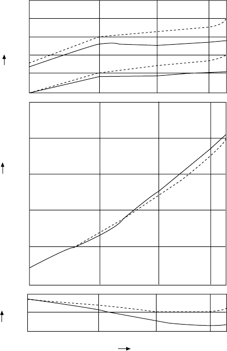
Figure 7.30 Turbocharger retrot benets exhaust-gas temperatures and specic
fuel consumption of an aBB VTr..1 turbocharger exhibiting low eciency (dashed
lines) compared with a replacement VTr..4 turbocharger operating with a markedly
higher eciency (continuous lines)
230 Pressure Charging
54 per cent with virtually no effect on the exhaust gas energy available for con-
ventional waste heat recovery (Figure 7.31).
Apart from yielding worthwhile fuel savings throughout the engine load
range, the efficiency booster system can be an attractive alternative to engine
derating for an equivalent brake specific fuel consumption. Compared with a
derated engine, the system may allow the saving of one cylinder (depending on
the type of engine and its power/speed rating), with consequent benefits in both
a lower first cost and a shorter engineroom.
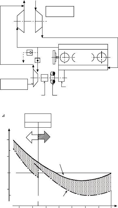
The efficiency booster is described as a straightforward on/off system,
which can be exploited above 40–50 per cent engine load without undermining
engine reliability. Exhaust energy is recovered simply by diverting a proportion
Emergency
bypass
line with
orifice
Schematic arrangement
of the Sulzer Efficiency-
Booster system
Flap
Power take-off gear
Hydraulic coupling
BBC Epicyclic gear
Reduction in brake
specific fuel
consumption using
the Sulzer Efficiency-
Booster system
- Booster
Off on
BSFC
(g/kWh)
(g/bhph)
BSFC of engine without-Booster
BSFC of engine with-Booster
30 40 50 60 70 80 90 100
Power [%]
Turbocharger
BBC VTR-4A
Exhaust gas receiver
BBC NTC-4
Power turbine
Engine
Exhaust Air
gas
Scavenge air receiver
–5
0
5
10
0
5
–5
Figure 7.31 sulzer eciency booster system layout and performance
of the exhaust gas from the exhaust manifold to a standard ABB turbocharger-
type power turbine arranged in parallel with the engine turbochargers. The
power turbine—forming a compact module with its integrated epicyclic gear—
is mechanically coupled to the Wärtsilä (Sulzer) RTA low-speed engine’s
integral PTO gear. The recovered energy is thus directly fed to the engine
crankshaft, allowing the engine to run at a correspondingly reduced load to
deliver the same total power to the propeller shaft—but with a correspondingly
lower fuel consumption. The result depends on the engine’s contract-maximum
continuous rating since fuel savings increase with bmep.
The simple mechanical arrangement, based on standard components, under-
writes a low first cost and offers a high transmission efficiency. It also allows
the efficiency booster to be shut off at engine part load and when manoeuvring.
Similar benefits are reported for MAN Diesel’s turbo compound system/
power take-in (TCS/PTI) arrangement, which can be fitted to its MC low-speed
engines with bore sizes from 600 mm to 900 mm (Figure 7.32). The system is
not applicable to smaller models because of their size and the lower efficiency
of the smaller turbochargers used. MAN Diesel and ABB power turbines are
used, respectively, in association with the MAN Diesel and ABB turbochargers
serving the engine. At engine loads above 50 per cent of the optimized power,
the power turbine is connected to the crankshaft via a hydraulic clutch and
flexible coupling.
kBB turbochargers 231
Power turbine
Epicyclic gear
Hydraulic
coupling
Bevel gear
Crankshaft
Flexible coupling
Toothed coupling
Crankshaft gear
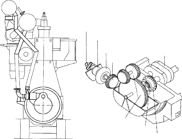
Figure 7.32 arrangement of Man TCs/PTi system on the main engine and the
power turbine drive to the crankshaft
232 Pressure Charging
The amounts of exhaust gas actually available for the TCS depends on the
turbocharger efficiency and turbocharger matching chosen for the individual
case. TCS power falls off at lower loads owing to the smaller gas amounts:
at 50 per cent of the optimized engine power the output of the TCS/PTI
unit is around 25 per cent, returning negligible savings in the specific fuel
consumption of the engine. The maximum power turbine output obtainable is
4.2 per cent of the engine’s optimized power, the yield depending on the tur-
bocharger selected.
MAN Diesel’s PTO/PTI system combines a PTO serving a generator and
a TCS/PTI unit (power turbine coupled to the crankshaft gear). The combined
benefits of both systems are achieved without incurring the full first cost asso-
ciated with each as some of the most costly elements (e.g., the crankshaft gear)
are common.
Engines equipped with high-efficiency turbochargers can operate without
auxiliary blowers at lower loads (down to around 25 per cent) than engines
with standard turbochargers (around 35 per cent).
Based on its MET-MA turbocharger’s turbine design, Mitsubishi has devel-
oped the MPT-A series power turbine for application in advanced waste heat
recovery turbo compound systems.
Turbocharger generator/Motors
Advances in high-speed generator technology as well as in high-capacity elec-
tronic switching devices have fostered the practical development of compact,
high-output generators and frequency converters suitable for use in combination
with turbochargers. Such so-called hybrid turbochargers—in which a high-
speed generator is attached directly to the turbocharger rotor shaft—offer these
advantages over conventional turbo compound systems based on a power gas
turbine, according to Mitsubishi:
l Elimination of piping and valves associated with feeding exhaust gas to
a power turbine
l Control of turbocharger performance by raising and lowering generator
output
l Use of the generator as a motor as a substitute for the auxiliary blower
of two-stroke engines; motor mode can also be applied to accelerate the
turbocharger rotor and improve turbocharger performance, particularly
at the low load range of the engine
l High efficiency due to energy conversion by the turbocharger turbine.
Working in conjunction with a specialist generator manufacturer, Mitsubishi
has developed a suitable high-speed/high-capacity generator for use with hybrid
turbochargers. The four-pole permanent magnet synchronous machine has a rated
speed of 18 700 rev/min and a maximum permissible speed of 22 300 rev/min,
with a maximum output rating of 252 kW.
Mitsubishi summarizes that hybrid turbochargers incorporating a genera-
tor/motor enable the combustion air to be adjusted optimally in response to
engine operating conditions by raising and lowering the amount of output
power generated, or—in motor mode—the amount of electrical power used
to assist the turbocharger (representing a possible new mode of controlling
diesel engines).
See also Chapter 30 for sequential turbocharging (MTU and SEMT-Pielstick)
and two-stage turbocharging systems (Niigata and Paxman); Chapter 27 for
Wärtsilä SPEX system and Chapter 11 for Mitsubishi two-stage turbocharging
system.
kBB turbochargers 233
235
C h a p t e r | e i g h t
Fuel Injection
The emphasis in this chapter is on four-stroke medium- and high-speed engines
with camshaft-actuated individual jerk pumps for each cylinder or common
rail (CR) fuel injection systems and does not apply, except in a general way,
to low-speed two-stroke engines whose fuel injection systems are discussed in
later chapters under individual designs.
InjeCtIon and CombustIon
The essence of a diesel engine is the introduction of finely atomized fuel into
the air compressed in the cylinder during the piston’s inward stroke. It is, of
course, the heat generated by this compression, which is normally nearly adi-
abatic, that is crucial in achieving ignition. Although the pressure in the cylin-
der at this point is likely to be anything up to 230 bar, the fuel pressure at the
atomizer will be of the order of 1300–1800 bar.
High injection pressures at full load are beneficial in terms of fuel econ-
omy, emissions and the ability to accept inferior fuel. Most modern medium-
speed engines attain 1200–1800 bar in the high-pressure (HP) injection pipe,
although some recent engine designs achieve as much as 2300 bar when pump-
ing heavy fuel. For reasons of available technology, the earliest diesel engines
had to use compressed air to achieve atomization of the fuel as it entered the
cylinder (air blast injection), and while airless (or solid) injection delivered a
significant reduction in parasitic loads, it also presented considerable problems
in the need for high precision manufacture, and the containment of very high
and complex stresses.
The very high standard of reliability and lifetime now attained by modern
fuel injection systems is the result of considerable investment in R&D and pro-
duction technology by designers and equipment manufacturers. Ultra-high pre-
cision machining facilities for flat and curved surfaces are dictated for injection
systems operating at pressures of up to 2000 bar and beyond, calling for mini-
mal manufacturing tolerances down to 0.001 mm and the highest cleanliness
in all processes. A particularly challenging component is the injector needle,
236 Fuel Injection
which, in some systems, requires microscopic helical grooves to be machined
into the pin shaft to hydraulically absorb lateral forces with the aid of the fuel.
In the early days of airless injection, many ingenious varieties of combus-
tion chamber were used, sometimes mainly to reduce noise or smoke, or to
ease starting, but often in part to reduce or to use modest injection and com-
bustion pressures. A growing emphasis on economy and specific output, cou-
pled with materials development and advances in calculation methods allowing
greater loads to be carried safely, has left the direct injection principle domi-
nant in modern medium- and high-speed engine practice.
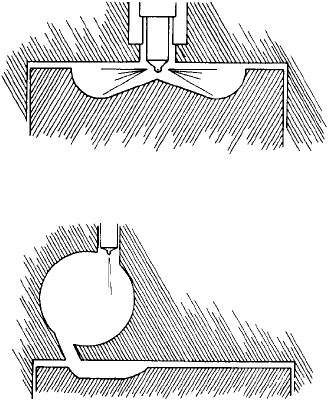
In direct injection systems the fuel is delivered directly into a single com-
bustion chamber formed in the cylinder space (Figure 8.1), atomization being
achieved as the fuel issues from small drillings in the nozzle tip.
For complete combustion of the fuel to take place, every droplet of fuel must
be exposed to the correct proportion of air to achieve complete oxidation, or to
an excess of air. In the direct injection engine, the fuel/air mixing is achieved
by the energy in the fuel spray propelling the droplets into the hot, dense air.
Additional mixing may be achieved by the orderly movement of the air in the
combustion chamber, which is called ‘air swirl’. Naturally aspirated engines usu-
ally have a degree of swirl and an injection pressure of around 800 bar. Highly
turbocharged engines with four-valve heads have virtually no swirl, but typically
have an injection pressure of 1200–1800 bar to provide the mixing energy.
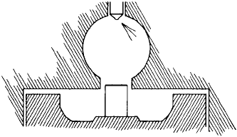
Where indirect injection is exploited, some high-speed engines retain a pre-
chamber in the cylinder head into which fuel is injected as a relatively coarse
spray at low pressure, sometimes using a single hole. Combustion is initiated
in the pre-chamber, the burning gases issuing through the throat of the chamber
to act on the piston (Figure 8.2).
FIgure 8.1 Cross-section of direct injection combustion chamber
FIgure 8.2 Indirect injection: the ricardo pre-chamber
Fuel/air mixing is achieved by a very high air velocity in the chamber, the
air movement scouring the walls of the chamber and promoting good heat
transfer. Thus the wall can be very hot—requiring heat-resistant materials—
but it can also absorb too much heat from the air in the initial compression
strokes during starting and prevent ignition. It is these heat losses that lead to
poor starting and inferior economy. Further forms of assistance, such as glow
plugs, have therefore sometimes been necessary to achieve starting when ambi-
ent pressures are low. The throttling loss entailed by the restricting throat also
imposes an additional fuel consumption penalty.
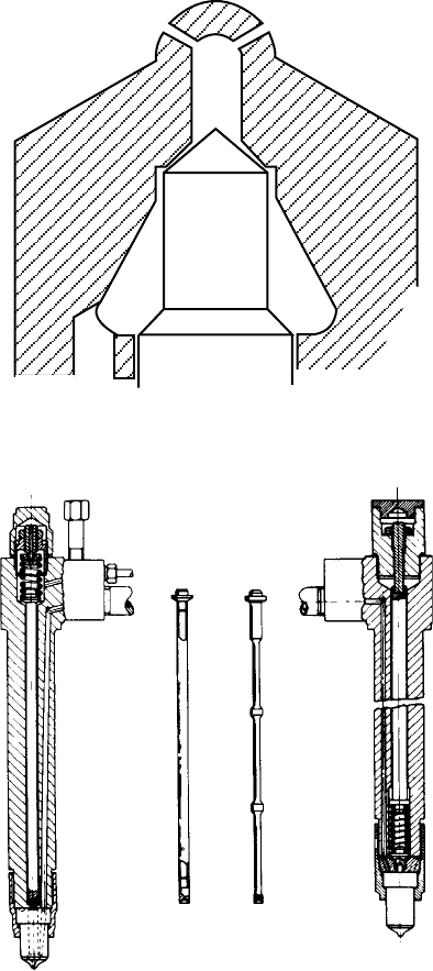
One engine designer, SEMT-Pielstick, achieved an ingenious combination
of the two systems by dividing the pre-chamber between cylinder head and
piston crown. At top dead centre a stud on the piston enters the pre-chamber
to provide a restricted outlet. On the expansion stroke, the restriction is auto-
matically removed and fuel economy comparable with normal direct injection
engines is attainable (Figure 8.3).
Direct injection, too, has variants, which reflect the fact that, despite
considerable expenditure on research into its mechanism, the detail of how
combustion develops after ignition is achieved is still largely empirical. The
essentials are as follows:
1. At least some of the fuel injected is atomized sufficiently finely to initi-
ate combustion. Ignition cannot take place until a droplet of fuel has
reached the temperature for spontaneous ignition. Since heat is taken
up as a function of surface area (proportional to the square of the dia-
meter) and the quantity of heat needed to achieve a temperature rise is
a function of volume (varying as the cube of the diameter), only a small
number of fine droplets are needed to initiate combustion. High-speed
photography of combustion does indeed show that ignition takes place
in a random manner near the injector tip and usually outside the main
core of the spray.
2. The fuel should mix with the air in order to burn. Since most of the
air in a roughly cylindrical space is, for geometrical reasons, near the
periphery, most of the fuel must penetrate there, and this is easier with
large droplets; hence, also, the use of wide core angles and multiple
spray holes.
Injection and combustion 237
FIgure 8.3 the variable geometry combustion chamber of semt-Pielstick
238 Fuel Injection
3. Under no circumstances must fuel reach the liner walls, or it will con-
taminate the lubricating oil. An advantage of combustion spaces formed
in piston crowns is that the walls of the chamber form a safe target at
which spray may be directed. This type of combustion chamber in the
piston has the further advantage that, during the piston descent, air
above the piston periphery is drawn into the combustion process in a
progressive manner.
4. The injection period should be reasonably short and must end sharply.
Dribble and secondary injection are frequent causes of smoke, and also
of lubricating oil becoming diluted with fuel or loaded with insoluble
residues. Dribble is the condition where fuel continues to emerge from
the nozzle at pressures too low to atomize properly; it is caused by bad
seating faces or slow closure.
Secondary injection is what happens when the pressure wave caused by the
end of the main injection is reflected back to the pump and then again to the
injector, reaching it with sufficient pressure to reopen the injector at a relatively
late stage in combustion. Any unburned or partly burned fuel may find its way
onto the cylinder walls and be drawn down by the piston rings to the sump.
InjeCtor
Working backwards from the desired result to the means to achieve it, the
injector has to snap open when the timed HP wave from the pump travelling
along the HP pipe has reached the injector needle valve. Needle lift is limited
by the gap between its upper shoulder and the main body of the holder. Needle
lift is opposed by a spring, set to keep the needle seated until the ‘blow-off
pressure’ or ‘release pressure’ of the injector is reached by the fuel as the pres-
sure wave arrives from the pump. This pressure is chosen by the enginebuilder
to ensure that there is no tendency for the needle to reopen as the closing pres-
sure waves are reflected back and forth along the HP pipe from the pump. The
setting also has some effect on injection delay and the quality of injection; it is
usually chosen to be between 200 bar and 300 bar.
The needle valve is invariably provided with an outer diameter on which
the fuel pressure acts to overcome the spring pressure and cause the initial lift.
This brings into play the central diameter of the needle so that it snaps open to
the lift permitted.
The needle and the seat cones are usually ground to a differential angle
so that contact is made at the larger diameter (Figure 8.4). When the needle is
only slightly open, the greater restriction to flow is at the outer rather than the
inner diameter of the seat. This ensures that as the needle lifts, there is a sud-
den change of pressurized area and the needle force against the spring changes
correspondingly, giving a very rapid lift to fully open; and conversely when
closing. (This is why it is bad practice to lap the needle to its seat.)
Control of the temperature of the injector, particularly of the sensitive
region round the needle seat and the sac, is very important. This is especially so
when heavy fuels are used, both because the fuels themselves have to be heated
and because they tend to burn with a more luminous flame that increases the
heat input to all the metal surfaces. If the tip temperature rises too high, the fuel
remaining in the sac after injection boils and spits from the spray holes: it is
not properly burned and forms a carbon deposit around each spray hole. Such
Injector 239
FIgure 8.4 detail of needle and seat showing dierential angle (exaggerated)
(a) (b) (c) (d)
FIgure 8.5 Comparison of traditional and low inertia injectors: (a) conventional
injector, (b) and (c) lightweight spindles, (d) low-inertia injector (delphi bryce)