Woodyard D. (ed.) Pounders Marine diesel engines and Gas Turbines
Подождите немного. Документ загружается.


MAN B&W low-speed engines 291
Table 10.1 Milestones in evolving MAN Diesel’s MAN B&W MC programme
Year Development Mark Mean Eective
Pressure (bar)
Mean Piston
Speed (m/s)
P
max
(bar)
1981 L35MC introduced
1982 Full L-MC programme 1 15.0 7.2
1984 L-MC upgraded 2 16.2
1985 L42MC introduced 2 16.2 7.2
1986 K-MC introduced
S-MC introduced
L-MC upgraded
3
3
3
16.2
17.0
16.2
7.6
7.8
7.6
130
130
130
1987 S26MC introduced 16.8 8.2
1988 K-MC-C introduced 3 16.2 8.0 130
1991 MC programme updated 8.0
K and L-MC
S-MC
5
6
18.0
18.0
8.0 140
1992 S26MC and L35MC
updated
18.5 8.2
1993 S35MC and S90MC-T
introduced
K90MC/MC-C updated
6 18.0 8.0
1994 S42MC introduced
K98MC-C introduced
6
6
18.5
18.2
8.0
8.3
140
1995 K80MC-C upgraded 6 18.0 8.0
1996 L70MC upgraded
S70MC-C, S60MC-C,
S50MC-C introduced
S46MC-C introduced
6
7
7
18.0
19.0
19.0
8.2
8.5
8.3
150
150
1997 L80MC upgraded
K98MC introduced
6
6
18.0
18.2
8.0
8.3
140
1998 S80MC-C, S90MC-C,
L90MC-C introduced
S35MC upgraded
7
7
19.0
19.1
8.1
8.1
150
145
1999 S42MC upgraded 7 19.5
8.0
2001 L70MC-C introduced
L60MC-C introduced
7
7
19.0
19.0
8.5
8.3
150
150
292 MAN B&W Low-Speed Engines
rating (mcr). Based on the propulsion and the engine running points, the layout
diagram of a relevant main engine can be drawn in. The specified mcr point
(M) must be inside or on the limitation lines of the layout diagram; if not,
the propeller speed has to be changed or another main engine model must be
chosen. It is only in special cases that point M may be located to the right of
line L1–L2.
The specified mcr is the maximum rating required by the yard or owner for
continuous operation of the chosen engine. Point M can be any point within the
layout diagram. Once the specified mcr point has been selected, and provided
that the shaftline and auxiliary equipment are dimensioned accordingly, that
point is now the maximum rating at which an overload of 10 per cent is per-
missible for 1 h in 12 h. The continuous service rating (S) is the power at which
the engine is normally assumed to operate; point S is identical to the service
propulsion point (SP) unless a main engine-driven shaft generator is installed.
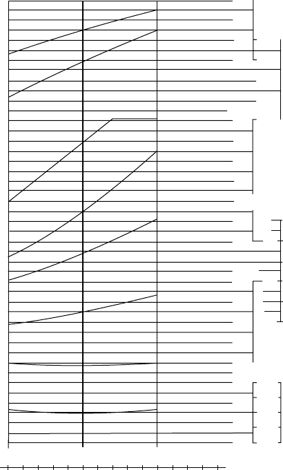
50% 75% 100% LOAD
1390 2085 2780 BHP/CYL
110
100
90
80
bar
17
15
13
11
9
MEP
P
Comp
P
Max
bar (abs)
140
130
120
110
100
90
80
bar
(abs)
P
Scav.
3.
2.
1.
dg. C
450
400
350
300
250
g/BHPh g/kWh
140
130
120
110
190
180
170
160
150
Engine speed
Mean effective
pressure
Maximum combustion
pressure
Compression pressure
Scavenge air pressure
Exhaust gas temperature
inlet to turbocharger
Exhaust gas temperature
outlet from turbocharger
Specific fuel oil
consumption
T-Exhaust gas
FigurE 10.2 Performance curves for S60MC engine
All MC engines can be delivered to comply with the IMO speed-dependent
NOx emission limits for the exhaust gas, measured according to the ISO
8178 test cycles E2/E3 for heavy duty diesel engines. NOx emissions from a
given engine will vary according to the engine load and the optimizing power.
Specific fuel consumption (sfc) and NOx emission levels are interrelated
parameters, and an engine offered with both a guaranteed sfc and the IMO
NOx limitation will be subject to a tolerance of 5 per cent on the fuel con-
sumption (see also Chapter 3).
MC ENgiNE DESigN FEATurES
All MC series engine models are based on the same design principles and aim
for simplicity and reliability, the key elements comprising the following:
Bedplate. The rigid bedplate for the large bore engines is built up of longi-
tudinal side girders and welded crossgirders with cast steel bearing supports.
For the smaller bore engine types, the bedplate is of cast iron. It is designed for
long, elastic holding-down bolts arranged in a single row and tightened with
hydraulic tools. The main bearings are lined with white metal, and the thrust
bearing is incorporated in the aft end of the bedplate. The aft-most crossgirder
is therefore designed with ample stiffness to transmit the variable thrust from
the thrust collar to the engine seating.
MC engine design features 293
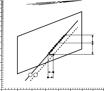
Engine margin
SP = 90% of MP
Sea margin
15% of PD
70% 75% 80% 85% 90% 95% 100% 105% 110%
Engine speed, % of L
1
MP
SP
L
1
L
2
L
3
L
4
α
= 0, 15
α = 0, 20
α = 0, 25 α = 0, 30
Power, % of L
1
110%
40%
50%
60%
70%
80%
90%
100%
2
PD
HR
LR
6
Line 2 Propulsion curve, fouled hull and heavy weather (heavy running)
Line 6 Propulsion curve, clean hull and calm weather (light running)
MP Specified MCR for propulsion
SP Continuous service rating for propulsion
PD Propeller design point
HR Heavy running
LR Light running
FigurE 10.3 Ship propulsion running points and engine layout for S60MC model.
Line 2, propulsion curve, fouled hull and heavy weather (heavy running); Line 6,
propulsion curve, clean hull and calm weather (light running); MP, specied MCr for
propulsion; SP, continuous service rating for propulsion; PD, propeller design point;
Hr, heavy running; Lr, light running
294 MAN B&W Low-Speed Engines
Framebox. This is a single welded unit for the large bore models and a cast
iron unit for the smaller types, the design contributing to a very rigid engine
structure. The framebox is equipped on the exhaust side with a relief valve and
on the camshaft side with a large door for each cylinder providing access to the
crankcase components.
Cylinder frame. The cast iron cylinder frames on the top of the framebox
make another significant contribution to the rigidity of the overall engine struc-
ture. The frames include the scavenge boxes, which are dimensioned to ensure
that scavenge air is admitted uniformly to the cylinders. Staybolts are tightened
hydraulically to connect the bedplate, the framebox and cylinder frames, and
form a very rigid unit.
Crankshaft. The conventional semi-built, shrink-fitted type crankshaft is
provided with a thrust collar. The sprocket rim for the camshaft chain drive
is fitted on the outer circumference of the thrust collar in order to reduce
the overall length of the engine—except for the high cylinder numbers of the
800-mm bore model and upwards in the programme for which the chain drive
is located between two cylinders. An axial vibration damper is integrated on
the free end of the crankshaft.
Connecting rod. In order to limit the height of the engines, a relatively
short connecting rod, comprising few principal parts, is specified. The large
area of the lower half of the crosshead bearing allows the use of white metal
or tin–aluminium on the small bore engine models. Floating guide shoes mean
that most of the alignment work formerly required with crosshead engine
pistons can be eliminated. The crankpin bearing for all engine models features
thin shells lined with white metal.
Cylinder liner. A simple symmetrical design fosters low lubricating oil
consumption and low wear rates. The liner is bore cooled on the larger engine
models and available in two different configurations—with or without insula-
tion of the cooling water jet pipes—so as to match the cooling intensity closely
to the different engine ratings. The joint between liner and cover is located
relatively low. This arrangement means that a larger part of the heat-exposed
combustion chamber is contained in the steel cylinder cover rather than in the
cast iron cylinder liner. Smaller bore engines feature a simple slim-type liner
without cooling bores. For both types of liner, adequate temperature control of
the liner surfaces safeguards against cold corrosion caused by the condensation
of sulphuric acid (originating from the sulphur content of heavy fuel) and, at
the same time, ensures stable lubrication conditions by preventing excessive
temperatures (Figure 10.4).
Cylinder cover. This is a solid steel component provided with bored pas-
sages for cooling water, a central bore for the exhaust valve and bores for fuel
valves, safety valve, starting valve and indicator valve.
Piston. An oil-cooled piston crown of heat-resistant chrome–molybdenum
steel is rigidly bolted to the piston rod to allow distortion-free transmission of
the firing pressure. The piston has four ring grooves, which are hard chrome
plated on both upper and lower surfaces of the grooves. A cast iron piston skirt
(with bronze sliding bands on the large bore engines) is bolted to the underside
of the piston crown (Figures 10.5 and 10.6).
Piston rod. The rod is surface treated to minimize friction in the stuffing
box and to allow a higher sealing ring contact pressure. The piston rod stuffing
box, providing effective sealing between the clean crankcase and the ‘combus-
tion area’, has a proven record of very low amounts of drainage oil.
Camshaft. The fuel injection pumps and the hydraulic exhaust valve actua-
tors are driven by the camshaft. Cams are shrink-fitted to the shaft and can be
individually adjusted by the high-pressure oil method. Like its predecessors,
the MC engine uses a chain drive to operate the camshaft and thus secures high
reliability since a chain is virtually immune to foreign particles. It also enables
the camshaft to be positioned higher, shortening the hydraulic connections to
the fuel valves and the exhaust valves and, in turn, minimizing timing errors
due to elasticity and pressure fluctuations in the pipe system.
Exhaust valve. Hydraulic oil supplied from the actuator opens the exhaust
valve, and the closing force is delivered by a ‘pneumatic spring’, which leaves
the valve spindle free to rotate. The closing of the valve is damped by an oil
cushion on top of the spindle. The rotation force is provided by exhaust gas
acting on vanes fitted to the valve stem. Extended service life from the valve
is underwritten by Nimonic valve spindles and hardened steel bottom pieces,
MC engine design features 295
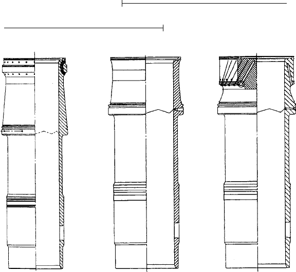
Cast-in cooling pipes ‘Slim liner’
Bore-cooled
26–50MC
2nd generationMC
60–90MC
1st generationMC
60–90MC
60–70MCE
FigurE 10.4 Cylinder liner designs
296 MAN B&W Low-Speed Engines
S-MC-Mk 5 S50/60/70MC-C and L70MC Mk 6
with high topland
FigurE 10.5 Piston/ring pack assembly MC vs. MC-C engines
Inconel layer for TCS and K-MC-C plants
Relief groove
Hardened
New standard on 90–60MC
Piston skirt with lead–
bronze bands
Surface of O-ring
groove etc. N7 (smooth)
FigurE 10.6 Piston assembly
specified as standard on the large bore engines. The bottom piece features pat-
ented ‘chamber-in-seat’ geometry.
Fuel pump. Larger engine models incorporate pumps with variable
injection timing for optimizing fuel economy at part load; the start of fuel
injection is controlled by altering the pump barrel position via a toothed
rack and a servo unit. Individual adjustment can be made on each cylinder.
Additionally, collective adjustment of the maximum pressure level of the
engine can be carried out to compensate for varying fuel qualities, wear and
other factors. Both adjustments can be effected while the engine is running.
The pump is provided with a puncture valve, which prevents fuel injection dur-
ing normal stopping and shutdown.
Fuel oil system. The engine is served by a closed pressurized fuel oil
system, with the fuel preheated to a maximum of 150°C to ensure a suitable
injection viscosity. The fuel injection valves are uncooled. The fuel system is
kept warm by the circulation of heated fuel oil, thus allowing pier-to-pier oper-
ation on heavy fuel oil.
Reversing mechanism. The engine is reversed by a simple and reliable
mechanism, which incorporates an angularly displaceable roller in the fuel
pump drive of each cylinder. The link connecting the roller guide and the roller
is self-locking in the ahead and astern positions. The link is activated by com-
pressed air, which has proved to be a very reliable method, since each cylinder
is reversed individually. The engine remains manoeuvrable even if one cylinder
fails: in such a case the relevant fuel pump is set to the zero index position.
Shaft generators. All MC engines can be arranged to drive shaft genera-
tors. The power take-off/Renk constant frequency (PTO/RCF) system is MAN
Diesel’s standard configuration for PTOs from 420-mm bore models and
upwards coupled to a fixed pitch propeller. The system is mounted on brack-
ets along the bedplate on the exhaust side of the engine. The generator and its
drive are isolated from torsional and axial vibrations in the engine by an elas-
tic coupling and a tooth coupling mounted on a flange on the free end of the
crankshaft. The drive comprises a three-wheel gear train. To ensure a constant
frequency, the planetary gear incorporates a hydraulic speed control arrange-
ment, which varies the gearing ratio. The frequency is kept constant down to
70 per cent of the main engine’s specified mcr speed, corresponding to 30 per
cent of the engine’s specified mcr power, making the system suitable for fixed
pitch propeller installations.
The PTO/gear constant ratio (GCR) system is MAN Diesel’s standard
solution for PTO in plants featuring controllable pitch propellers. The system
comprises a compact unit with a step-up gear coupled directly to the generator,
which is located above the elastic coupling.
Power turbines. Larger MC engines (from 600-mm bore upwards) can be
specified with a turbo compound system (TCS), which exploits exhaust energy
surplus to the requirements of a high-efficiency turbocharger to drive a power
gas turbine (see Chapter 7). For engine loads above 50 per cent of the opti-
mized power, the gas turbine is mechanically or hydraulically connected to the
MC engine design features 297
298 MAN B&W Low-Speed Engines
crankshaft. Power is fed back to the main engine, thus reducing the total fuel
consumption. The standard system, designated TCS/power take-in (PTI)), is
delivered as a complete unit built on the engine. A combined PTO/PTI unit
embracing a PTO with associated generator and a TCS/PTI unit with a power
turbine coupled to the crankshaft gear is also offered.
ProgrAMME ExPANSioN
New models have entered the MC programme since its launch in response
to propulsion market trends at both ends of the power spectrum. A notable
addition in 1986—the S26MC series—took the low-speed engine deep into
small-ship propulsion territory, offering an output per cylinder of 365 kW at
250 rev/min. The nominal power of the 260-mm-bore/980-mm-stroke design
has since been raised to 400 kW at 250 rev/min and the 4- to 12-cylinder pro-
gramme covers an output range from 1100 kW to 4800 kW. With a stroke–bore
ratio of 3.77:1, this rating corresponds to a mean piston speed of 8.2 m/s and a
mean effective pressure of 18.5 bar. A firing pressure of around 170 bar yields
an sfc of 179 g/kW h at the mcr. Reliable operation on poor quality heavy fuel
oil with a viscosity of up to 700 cSt/50°C is promised.
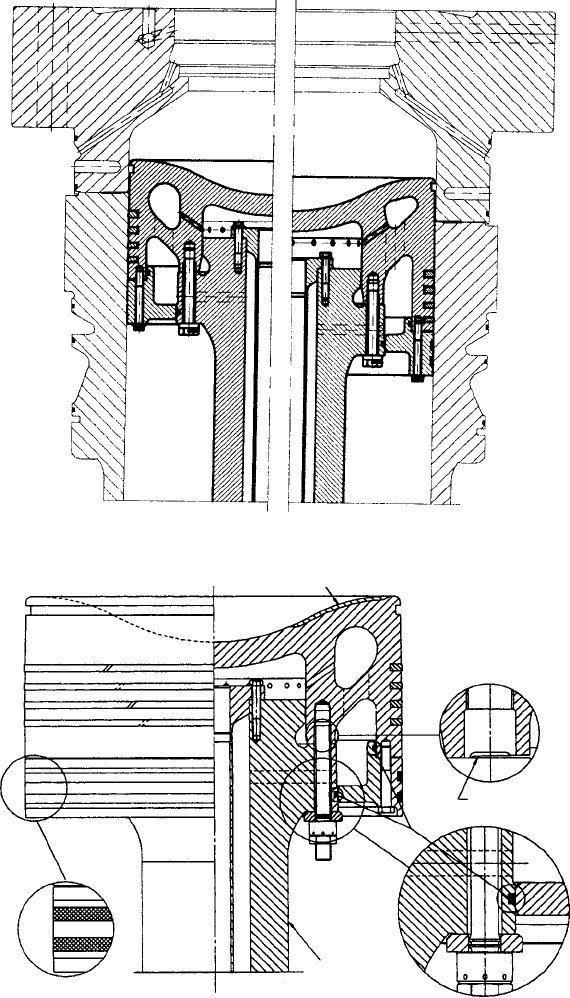
The key components of the S26MC engine (Figure 10.7) are based on those
well proven in the established larger bore models but with modifications to
suit the intended small-ship market. Design amendments since its introduction
include an improved axial vibration damper and refinements to the crankshaft.
The cylinder cover and fuel injection system have also been upgraded, the auxi-
liary blower arrangement simplified and the exhaust valve provided with a new
closing system with built-in damping.
Similar refinements have benefited the L35MC engine, which pioneered
the MC programme. An upgrading in 1992 sought improved performance and
reduced maintenance costs, the new maximum power rating of 650 kW/cylin-
der at 210 rev/min, mean effective pressure of 18.4 bar and mean piston speed
of 7.35 m/s calling for increased diameters of the main and crankpin journals,
and reinforcement of the main bearing housing and bedplate. The crosshead
bearing, thrust bearing and piston and piston rod were also reinforced, and
the cylinder frame, camshaft arrangement and auxiliary blower arrangement
simplified.
A longer stroke S-version of the 350-mm bore design was introduced in
1993, this S35MC model delivering 700 kW/cylinder at 170 rev/min (since
increased to 740 kW/cylinder at 173 rev/min). A number of components were
modified in line with the longer stroke (1400 mm compared with 1050 mm),
but the main design features were unchanged.
The strong and rigid main structure of the S35MC is essentially the same as
the L35MC, but the bedplate and framebox are wider and higher due to the longer
stroke of the semi-built crankshaft. The connecting and piston rods are necessarily
longer, but the cylinder frame is identical. The main bearings are wider in order
to keep the bearing load inside the area ensuring good service results. Most of the
components in the S35MC combustion chamber are also similar to those of the
L-version. The exhaust valve design was unchanged but an improved sealing sys-
tem was introduced to further reduce the wear of the valve stem. The cylinder
cover is slightly higher to allow for the increased combustion space.
Multi-level cylinder lubrication was adopted to ensure sufficient lubrication
of the liner. A modified piston pack comprises two high rings in grooves 1 and
2, and two rings of normal height in grooves 3 and 4. All of the rings are made
from an improved material. The fuel pump plunger diameter was increased
to satisfy the larger injection volume per stroke; and improved sealing was
introduced to prevent any fuel from leaking into the main lube oil, which is
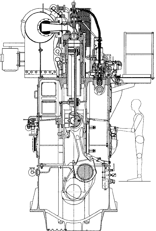
Programme expansion 299
FigurE 10.7 S26MC engine cross-section

300 MAN B&W Low-Speed Engines
common to the crankcase and camshaft. The camshaft diameter was increased
to accept the larger torque from the fuel pumps.
The S35MC and the 1994-launched S42MC series were conceived to
improve the propulsive efficiency of plants for small-to-medium-sized ships
by lowering the engine speed, these 350-mm bore and 420-mm bore models,
respectively, distinguished by stroke–bore ratios of 4:1 and 4.2:1. The later
introduction of the S46MC-C model (also exploiting a 4.2:1 stroke–bore ratio,
then the highest of any production engine in the world) addressed the needs
of smaller tankers and bulk carriers, which can also be served by the S42MC
and L or S50MC engines. The 460-mm bore model extended the number of
ideal combinations of power, speed and number of cylinders for a given project
(Table 10.2 and Figure 10.8).
Choice in the mid-bore range (500 mm, 600 mm and 700 mm models) was
widened from 1996 by uprated versions supplementing the existing S50MC,
S60MC and S70MC engines. These new S50MC-C, S60MC-C and S70MC-C
models, which share the same design features as the S46MC-C, are more com-
pact (hence the C-designation) and offer higher outputs than their established
equivalents (an L70MC engine is shown in Figure 10.9). Stroke–bore ratios
were raised from 3.82 to 4:1, and the increased power ratings correspond to a
rise in the mean effective pressure to 19 bar.
Supporting the higher ratings are modified turbocharging and scavenge
air systems as well as modifications of the combustion chamber configuration
and bearings. Installation space savings were achieved by reducing the overall
length of the C-engines (by around 1000 mm in the case of the six-cylinder
S50MC-C engine) and the overhauling height requirement compared with the
original designs. The masses are also lower (by 25 tonnes or 13 per cent for the
6S50MC-C), which yields benefits in reduced vibration excitations. The MC-C
engines can be 100 per cent balanced.
Table 10.2 S46MC-C engine
Bore 460 mm
Stroke 1932 mm
Stroke–bore ratio 4.2:1
Speed 129 rev/min
Mean eective pressure
19 bar
output/cylinder 1310 kW
Mean piston speed 8.3 m/s
Cylinders 4–8
Specic fuel consumption (mcr)
174 g/kW h