Woodyard D. (ed.) Pounders Marine diesel engines and Gas Turbines
Подождите немного. Документ загружается.

more than half and insoluble deposits in the oil reduced dramatically, signifi-
cantly extending oil filter life. Carbon-cutting rings can be retrofitted to deliver
their benefits to engines in service. Removal prior to piston withdrawal is sim-
ply effected with a special tool.
Designers now also favour a ‘hot box’ arrangement for the fuel injection
system to secure cleaner engine lines and improve the working environment
in the machinery room thanks to reduced temperatures; additionally, any fuel
leakage from the injection system components is retained within the box.
The major medium-speed enginebuilders have long offered 500-mm-
bore-plus designs in their portfolios. MAN Diesel still fields its L58/64 series
but MaK’s 580-mm bore M601 and the Sulzer ZA50S engines have been
phased out, as was Stork-Wärtsilä’s TM620 engine in the mid-1990s. In the
1970s MAN and Sulzer jointly developed a V-cylinder 650-mm bore/stroke
design (developing 1325 kW/cylinder at 400 rev/min) that did not proceed
beyond prototype testing.
Wärtsilä’s 64 series, launched in 1996, took the medium-speed engine
into a higher power and efficiency territory, the 640-mm bore/900-mm stroke
design now offering an output of 2010 kW/cylinder at 333 rev/min. A V12-
cylinder model delivers 23 280 kW at 400 rev/min. The range can therefore
meet the propulsive power demands of virtually all merchant ship tonnage
types with either single- or multi-engine installations. The key introductory
parameters were 10 m/s mean piston speed, 25 bar mean effective pressure,
and 190 bar maximum cylinder pressure. The Finnish designers claimed the
64 series to be the first medium-speed engine to exceed the 50 per cent ther-
mal efficiency barrier, and suggested that overall plant efficiencies of 57–58
per cent are possible from a combi-cycle exploiting waste heat to generate
steam for a turbo-alternator.
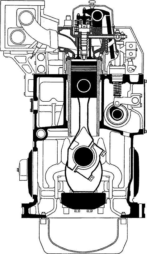
At the other end of the medium-speed engine power spectrum, the early
1990s saw the introduction of a number of 200-mm bore long stroke designs
from leading builders such as Daihatsu, MaK and Wärtsilä Diesel, contesting
a sector already targeted by Sulzer’s S20 model. These heavy fuel-burning
engines (typically with a 1.5:1 stroke–bore ratio) were evolved for small-ship
propulsion and genset drive duties, the development goals addressing over-
all operating economy, reliability, component durability, simplicity of main-
tenance and reduced production costs. Low and short overall configurations
gave more freedom to naval architects in planning machinery room layouts and
eased installation procedures (Figure 16.4).
The ~320-mm bore sector is fiercely contested by designers serving a high-
volume market created by propulsion and genset drive demands. A number of
new designs—including Caterpillar/MaK’s M32 and MAN Diesel’s L32/40—
emerged to challenge upgraded established models such as the Wärtsilä 32.
A Japanese challenger in a medium-speed arena traditionally dominated by
European designer/licensors arrived in the mid-1990s after several years’ R&D by
the Tokyo-based Advanced Diesel Engine Development Company. The joint ven-
ture embraced Hitachi Zosen, Kawasaki Heavy Industries and Mitsui Engineering
Medium-speed engines—introduction 513
514 Medium-Speed Engines—Introduction
and Shipbuilding. The 300-mm bore/480-mm stroke ADD30V design, in a V50-
degree configuration, developed up to 735 kW/cylinder at 750 rev/min, signifi-
cantly more powerful than contemporary medium-speed engines of equivalent
bore size. A mean effective pressure of around 25 bar and a mean piston speed of
11.5 m/s were exploited in tests with a six-cylinder prototype, although an mep
approaching 35 bar and a mean piston speed of 12 m/s are reportedly possible.
In addition to a high specific output, the developers sought a design,
which was also over 30 per cent lighter in weight, 10–15 per cent more fuel
economical and with a better part-load performance than established engines.
Underwriting these advances in mep and mean piston speed ratings are an
FIgurE 16.4 MaK’s M20 engine represented a new breed of 200-mm bore designs
anti-wear ceramic coating for the sliding surfaces of the cylinder liners and
piston rings, applied by a plasma coating method. A porous ceramic heat shield
was also developed for the combustion chamber to reduce heat transfer to the
base metal of the piston crown.
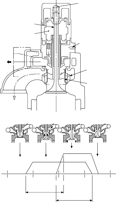
A key feature is the single-valve air intake and exhaust gas exchange
(Figure 16.5), contrasting with the four-valve (two inlet and two exhaust)
heads of other medium-speed engines. The greatly enlarged overall dynamic
valve area and the reduction in pressure losses during the gas exchange period
promote a higher thermal efficiency. The system is based on a heat-resistant
alloy main poppet valve located over the centre of the cylinder and a control
valve placed co-axially against this main valve. The control valve switches the
air intake and exhaust channels in the cylinder cover. Both main and control
valves are driven hydraulically.
Medium-speed engines—introduction 515
FIgurE 16.5 The Japanese ADD 30V engine is distinguished by a single-valve gas
exchange system comprising a main valve located at the centre of the cylinder and a
control valve placed co-axially against the main valve. The control valve switches the
air intake and exhaust channels in the cylinder cover. Both valves are driven hydrauli-
cally. Side-mounted fuel injectors are arranged around the cylinder periphery
516 Medium-Speed Engines—Introduction
Fuel injection is executed from the side through multiple injectors arranged
around the cylinder periphery instead of a conventional top-mounted central
injection system. Combustion characteristics were optimized by raising the
fuel injection pressure to around 2000 bar, thus enhancing the fuel–air mixture
formation and fostering low NOx emissions without sacrificing fuel economy.
A computer-based mechatronics system automatically controls the timing of
fuel injection and valve opening/closing to match the operating conditions.
The first 6ADD30V production marine engines, built by Mitsui, were specified
as the prime movers for the diesel-electric propulsion plant of a large Japanese
survey vessel.
Offshore vessel and LNG carrier propulsion market opportunities—and
the potential of wider mainstream shipping interest as environmental curbs
tighten—have encouraged a number of medium-speed enginebuilders to
develop dual-fuel and gas–diesel designs offering true multi-fuel capabilities
with high efficiency and reliability, and low carbon dioxide emissions. The
Hydraulic oil
for main valve
Hydraulic oil
for sub valve
Swirler
Sub valve
Air intake
Exhaust
Spring air
Main valve
Main valve
Sub valve
T.D.C.
B.D.C.
T.D.C.
Exhaust
Air intake
T.D.C.
B.D.C.
FIgurE 16.5 Functioning of the ADD 30 V engine’s single valve gas exchange system
engines can run on gas (with a small percentage of liquid pilot fuel) or entirely
on liquid fuel (marine diesel oil, heavy fuel or even crude oil). Switching from
one fuel to another is possible without interrupting power generation (see
Chapter 2).
The high cost of R&D to maintain a competitive programme and continu-
ing investment in production resources and global support services have stimu-
lated a number of joint ventures and takeovers in the four-stroke engine sector
in recent years. Most notable have been Wärtsilä’s acquisition of the former
New Sulzer Diesel and Caterpillar’s takeover of MaK. Earlier, Wärtsilä had
acquired another leading medium-speed enginebuilder, the Netherlands-based
Stork-Werkspoor Diesel. This trend towards an industry comprising a small
number of major multi-national players contesting the world market has con-
tinued with the absorption of the British companies Mirrlees Blackstone,
Paxman and Ruston (formerly part of Alstom Engines) into the MAN Diesel
group. Rolls-Royce inherited the Bergen Diesel interests in Norway through
the takeover of Vickers-Ulstein.
Considerable potential remains for further developing the power ratings
of medium-speed engines, whose cylinder technology has benefited in recent
years from an anti-polishing ring at the top of the liner, water distribution
rings, chrome–ceramic piston rings, pressurized skirt lubrication and nodular
cast iron/low friction skirt designs.
The pressure-lubricated skirt elevated the scuffing limit originally obtain-
ing by more than 50 bar, reduced piston slap force by 75 per cent and doubled
the lifetime of piston rings and grooves. Furthermore, it facilitated a reduc-
tion in lube oil consumption and, along with the simultaneous introduction
of the nodular cast iron skirt, practically eliminated the risk of piston seizure.
The anti-polishing ring dramatically improved cylinder liner lifetime beyond
100 000 h, and lube oil consumption became controllable and stable over
time, most engines today running at rates between 0.1 g/kW h and 0.5 g/kW h.
A further reduction in piston ring and groove wear was also achieved, and the
time-between-overhauls extended to 18 000–20 000 h. The ring itself is a wear
part but is turnable in four positions in a four-stroke engine, fostering a lengthy
lifetime for the component.
Such elements underwrite a capability to support a maximum cylinder
pressure of 250 bar of which 210–230 bar is already exploited in some engines
today. Leading designers such as Wärtsilä suggest that it may be possible to
work up towards 300 bar with the same basic technology for the cylinder unit,
although some areas need to be developed: bearing technology, for example,
where there is potential in both geometry and materials. A steel piston skirt
may become the most cost effective, and cooling of the piston top will probably
change from direct oil cooling to indirect. The higher maximum cylinder pres-
sure can be exploited for increasing the maximum effective pressure or improv-
ing the thermal efficiency of the process. Continuing to mould the development
of the medium-speed engine will be NOx and carbon dioxide emissions, fuel
flexibility, mean time-between-failures and reduced maintenance.
Medium-speed engines—introduction 517
518 Medium-Speed Engines—Introduction
DESIgNINg MEDIuM-SpEED ENgINES
Investment in the development of a new medium-speed engine may be com-
mitted for a number of reasons. The enginebuilder may need to extend its port-
folio with larger or smaller designs to complete the available range, to exploit
recently developed equipment and systems, or to enhance the reliability, availa-
bility and economy of the programme. As an alternative to a new design, it may
be possible to upgrade an existing engine having the potential for improved
power ratings, lower operational costs, reduced emissions and weight. An
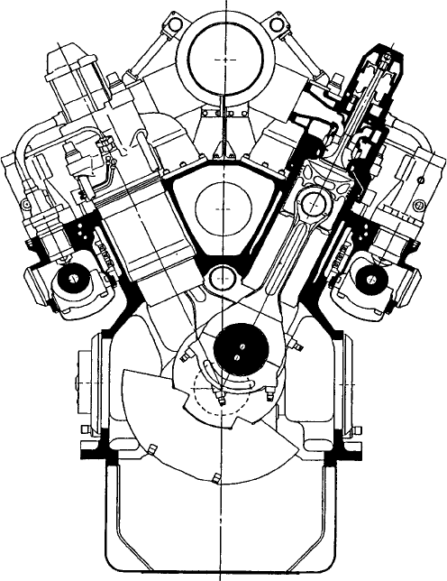
example is the upgrading by MAN Diesel of its 48/60 engine, whose B-version
offers a 14 per cent higher specific output with considerably reduced fuel con-
sumption and exhaust emission rates, a lower weight, and the same length and
height but a narrower overall width than its predecessor (Figure 16.6).
Having set the output range of the new engine, a decision must be made
on whether it should be built only as an in-line cylinder version or as a V-type
engine as well. In the case of the largest and heaviest medium-speed engines,
the efforts and costs involved in adding a V-type to the existing portfolio
might not be justified if there is a limited potential market for engines above
20 000 kW. Other restraining factors could be the capacity of the foundry for
casting very large crankcases or difficulties in transporting engines weighing
400 tonnes or more overland.
Once the power per cylinder of the proposed new engine is known, the first
indication of its bore size is determined by the piston load, which relates the
specific output to the circular piston surface. Piston loads have increased with
FIgurE 16.6 MAN Diesel’s 48/60 engine, shown here in V14-cylinder form, beneted
from a redesign that raised specic output by 14 per cent and reduced fuel con-
sumption and emissions

the development of better materials: the original 48/60 engine has a piston load
of 58 kW/cm
2
, while the 48/60B engine achieves 66.4 kW/cm
2
.
The bore and stroke of an engine are interrelated by the stroke–bore ratio,
which in turn is based on the designer’s experiences with earlier engines. Some
25 years ago it was not uncommon to design medium-speed engines with very
similar bore and stroke dimensions (so-called ‘square’ engines); more recently,
the trend has been towards longer stroke designs, which offer clear advantages
in optimizing the combustion space geometry to achieve lower NOx and soot
emission rates. A longer stroke can reduce NOx emissions with almost no fuel
economy penalty and without changing the maximum combustion pressure.
The compression ratio can also be increased more easily and, together with
a higher firing pressure, fuel consumption rates will decrease. Finally, long-
stroke engines yield an improved combustion quality, a better charge renewal
process inside the cylinder and higher mechanical efficiency.
A good compromise between an optimum stroke–bore ratio and the costs
involved, however, is an important factor: it is a general rule that the longer the
engine stroke, the higher the costs for an engine per kilowatt of output. The trend
towards longer stroke medium-speed engine designs is indicated by the follow-
ing table showing the current MAN Diesel family; the first four models were
launched between 1984 and 1995, and the remaining smaller models after 1996.
Model Stroke–Bore Ratio
58/64 1.1
48/60 1.25
40/54 1.35
32/40 1.25
27/38 1.41
21/31 1.47
16/24 1.5
This table is a simplified outline of the initial design process and the real-
ity is much more complex. The final configuration results from considering a
combination of choices, which may have different effects on fuel consumption
rates and emissions. Nevertheless, the usual trade-off between fuel economy
and NOx emissions can be eliminated. The use of high-efficiency turbocharg-
ers is also essential.
A decision on engine speed is the next step. The mean piston speed in
metres per second can be calculated from the bore and speed of an engine
using the following formula: mean piston speed (m/s) bore (m) speed
(rev/min)/30. The upper limit of the mean piston speed is primarily given by
the size and mass of the piston and the high forces acting on the connecting
rod and crankshaft during engine running. A mean speed between 9.5 m/s and
Designing medium-speed engines 519
520 Medium-Speed Engines—Introduction
slightly above 10 m/s is quite common for modern large bore medium-speed
engines. Any substantial increase above 10 m/s will reduce operational safety
and hence reliability. Since medium-speed engines may be specified to drive
propellers and/or alternators, the selection of engine speed has to satisfy the
interrelation between the frequency of an alternator (50 Hz or 60 Hz) and
the number of pole pairs.
In designing the individual engine components, two main criteria are
addressed: reducing manufacturing costs and reducing the number of overall
engine parts to ease maintenance.
A valuable summary of the design process is also provided by Rolls-Royce,
based on its development of the Allen 5000 series medium-speed engine in
conjunction with Ricardo Consulting Engineers of the United Kingdom. The
initial functional specification defined a target power of 500 kW/cylinder and
a wide application profile embracing industrial and standby power genera-
tion, pumping, propulsion and auxiliary power. It was considered essential to
design-in sufficient flexibility to accommodate all key parameters necessary
to ensure superior performance in these sectors well into the 21st century. The
following basic concepts were adopted by the design team:
l A power range of 3000–10 000 kW in steps of 1000 kW
l An output of 525 kWb per cylinder 10 per cent for 1 h in 12 h required
for power generation (equivalent to 500 kWe energy at both 720/750 rev/
min synchronous speeds)
l An output of 500 kWb per cylinder maximum continuous rating 10
per cent for 1 h in 12 h required for propulsion and pumping over a
speed range of 375–750 rev/min 15 per cent overspeed
l Fuel injection equipment to be of advanced technology, with the flexibil-
ity to satisfy future emissions legislation and specified fuel consumption
requirements
l Fuel flexibility covering heavy fuel oil and distillates
l High standards of reliability, durability and maintainability
l Condition monitoring capability essential
l Low number of parts.
The choice of brake mean effective pressure (bmep) was crucial to the
competitiveness of the design. It was essential to choose a bmep that would
allow the engine to be sold at a competitive price in pounds per kilowatt output.
Before commencing design work, therefore, a survey of competitive engines
was carried out. The survey showed that bmep levels increased on average by
0.25/0.33 bar per year, and predicted that in 1998 the highest rated engines
would have a rating of 25/25.3 bar. On this basis, coupled with engine econom-
ics, a rating of 26 bar bmep was selected for the new design. Cycle simulation
studies showed that this was achievable with a boost pressure ratio of 4.5:1,
provided that the combustion and injection systems were properly matched.
Any significant increase in bmep would dictate the use of boost pressures of
5:1 and, while turbochargers were available to deliver this level of performance,
the special features incorporated in them to achieve it commanded a premium
price and increased the cost of the engine.
To secure the specified power per cylinder of 525 kW at a speed of
720/750 rev/min (60 Hz and 50 Hz synchronous speeds), a cylinder bore between
310 mm and 330 mm was required. It was decided at the onset of the design
process to limit the maximum piston speed to 10.5 m/s, which equates to a
stroke of 420 mm. The bore–stroke ratio therefore lay between 1.2 and 1.4,
typical for an engine in the anticipated market sector.
Combustion system design is governed by the customer’s need for compli-
ance with exhaust emissions legislation and excellent fuel economy. This dic-
tates that the engine should have a high air–fuel ratio, a shallow open bowl
combustion chamber and a very high compression ratio. The fuel injection sys-
tem must be capable of generating at least 1600 bar line pressure; an injection
system with built-in capability to vary the injection timing was a key feature of
its specification.
In order to achieve a high trapped air–fuel ratio, the valve area should be
high and the ports designed for maximum efficiency with a small amount of
swirl (around 0.2–0.4 swirl ratio). The bowl shape should be wide and open
with no valve recesses, and the top ring should be placed reasonably high so
that the crevice volume is minimized to secure a high air utilization factor.
A maximum cylinder pressure target of 210 bar was chosen with the aim of
achieving excellent fuel economy; this in turn allows a high compression ratio
to be used (in the range 15.5–16.5:1). An injector nozzle with eight to ten holes
was specified. The combustion bowl design was optimized to ensure excellent
mixing of the fuel sprays to keep the air–fuel ratio as homogeneous as possible
and minimize the peak cycle temperatures and hence NOx formation.
The choice of bore size was influenced by considering the following: power
requirement (525 kW/cylinder), bmep (30 bar maximum), mean piston speed
(10.5 m/s), overall length/width/height, specific weight and specific cost.
To fulfil the design concept, the power requirement for the engine was
defined as 500 kWe/cylinder continuous rating with a 10 per cent overload
capacity. The maximum continuous bmep is 26.6 bar, a limit set by the availa-
ble boost pressure level from single-stage turbocharging. The limit of 10.25 m/s
mean piston speed was selected to allow reliable operation at the maximum
continuous speed without significant risk of piston, ring and liner scuffing
and wear problems. By selecting high values for rated bmep and mean piston
speed, the size of the cylinder components was minimized; this kept the overall
engine size small, with consequent benefits in production costs.
Having set the piston speed and bmep at rated speed, it is possible to
derive the piston area and hence the cylinder bore: 320 mm. Having limited the
mean piston speed to a maximum of 10.25 m/s at the maximum rated synchro-
nous speed of 750 rev/min, the maximum allowable stroke was determined as
410 mm. Supporting these decisions, simulation work using the WAVE pro-
gram was carried out to examine bore sizes from 315 mm to 330 mm and stroke
sizes from 380 mm to 420 mm. The results confirmed the selected values.
Designing medium-speed engines 521
522 Medium-Speed Engines—Introduction
Factors influencing the choice of cylinder configuration (in-line or V-form)
are weight, cost, installation limitations, stress limitations (crank), vibration
levels, production tooling and market acceptance. From manufacturing, weight,
cost and installation considerations, a V-form family appeared attractive.
V6- and V8-cylinder designs, however, have inherently poor vibration char-
acteristics and attempts to reduce this to acceptable levels would add cost and
complexity to the engines. The following configurations for the new engine
were therefore initially selected: in-line six and eight, and V10, 12, 14 and 16-
cylinders. (V18 and V20 models were subsequently added to the production
programme.)
The range of V-angles for competitive engines was from 45° to 60°, with
a compromise angle of 50° favoured by several manufacturers. Angles 45°
were considered impractical due to close proximity of the lower end of the left
and right bank cylinder liners. For even firing intervals and low torque fluctua-
tions to give acceptable cyclic speed variations, optimum V-angles vary from
72° for a V10 to 45° for a V16 engine. An investigation of the effects of
V-angle on cyclic torque fluctuations concluded that a common angle of 52°
was suitable for V12, 14 and 16 engines, while the V10 required an angle of
72° to optimize torque fluctuation and balance.
Simulating the performance of the Allen 5000 series engine was conducted
using a WAVE engine performance simulation model based on the in-line six-
cylinder design. For the concept design stage, the basic engine design para-
meters, such as fuel injection characteristics and valve events, were chosen and
then fixed. These were based on previous experience and data from engines of
a similar type with the aim of achieving good performance and emission char-
acteristics. The dimensions of the manifolding and air chest were typical for
this size of engine.
For the baseline simulation, an inlet cam period of 248° and an exhaust
period of 278° were chosen, with an injection period of 30° and start of injec-
tion at 13° before top dead centre. The port flow data were typical of a current
port design with a good flow performance. The trapped air–fuel ratio was set at
31:1 and a compression ratio of 14.5:1 applied.
The initial simulation model used a bore of 320 mm and a stroke of
390 mm. The results of the simulation showed that at the 10 per cent overload
condition, the predicted P
max
was 227 bar and the boost pressure 4.7 bar, which
were considered to be excessive. Increasing the stroke to 400 mm reduced the
P
max
to 202 bar and the boost pressure to 4.2 bar. Based on this initial bore and
stroke investigation, larger bore and stroke sizes were examined. This was con-
sidered necessary since there was a requirement for the engine to operate at
720 rev/min at the same rating of 525 kW/cylinder and also at the 10 per cent
overload condition, both of which result in higher cylinder pressures and boost
pressure requirements. Combinations of bore sizes of 320 mm, 325 mm and
330 mm and strokes of 410 mm, 415 mm and 420 mm were assessed for boost
pressure, P
max
and fuel consumption predictions.