Woodyard D. (ed.) Pounders Marine diesel engines and Gas Turbines
Подождите немного. Документ загружается.

Based on these simulations, it was decided to retain the bore size at
320 mm and increase the stroke to 410 mm; this would enable the engine to run
at full rating at 720 rev/min at the standard injection timing without exceeding
the P
max
limit of 210 bar. Having fixed the bore and stroke dimensions, varia-
tions in compression ratio and start of combustion were investigated for their
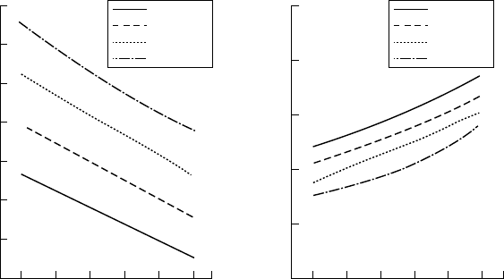
effect on fuel consumption and maximum cylinder pressure (see Figure 16.7).
Finally, the effect of valve size on performance was assessed before a 96-mm
diameter inlet valve and an 89-mm diameter exhaust valve were selected as the
optimum choice.
Acknowledgements: MAN Diesel, Rolls-Royce and Wärtsilä.
Designing medium-speed engines 523
CR 13.5
CR 14.5
CR 15.5
CR 16.5
−3 −2 −1 0 1 2
Start of combustion timing (Deg-ATDC)
200
196
192
188
184
180
BSFC (g/kW h)
−3 −2 −1 0 1 2
Start of combustion timing (Deg-ATDC)
CR 13.5
CR 14.5
CR 15.5
CR 16.5
225
215
205
195
185
175
165
155
P
max
(bar)
FIgurE 16.7 Development of Allen 5000 series engine: eect of variations in com-
pression ratio and start of combustion on maximum cylinder pressure (left) and fuel
consumption (right
) at a power rating of 525 kW/cylinder
525
C h a p t e r | s e v e n t e e n
Allen (Rolls-Royce)
The British designer Allen, Rolls-Royce company, fielded the S12/VS12 and
the S37/VS37 medium-speed engine series which were evolved over many
years but are no longer produced. The S12 was a 241 mm bore/305 mm stroke
design produced in four-, six-, eight- and nine-cylinder in-line versions cover-
ing a power band from 507 kW to 1584 kW at 720–1000 rev/min. The 325 mm
bore/370 mm stroke S37/VS37 design (Figure 17.1) was available in six, eight
and nine in-line and V12- and V16-cylinder forms to deliver outputs up to
5255 kW. The S12, VS12 and S37/VS37 designs were respectively rebranded
as the 2000 series, 3000 series and 4000 series.
The VS12 engine (which became the 3000 series) was first introduced in
the 1950s but benefited from a major redesign in 1990 to enhance compact-
ness and raise the power-to-weight and power-to-space ratios. V12- and V16-
cylinder versions of the 240 mm bore/300 mm stroke design covered a power
band from 1584 kW to 4160 kW at 900–1000 rev/min for propulsion and auxil-
iary power duties. Its rigid spheroidal graphite cast iron crankcase, designed to
carry the underslung forged steel crankshaft and main bearing caps, has inte-
gral mounting feet. The assembly is enclosed by a fabricated steel sump and a
cast iron gearcase. The single camshaft is carried in bearings centrally located
in the 60° vee between the cylinder banks and is driven by a gear train from the
crankshaft.
The one-piece crankshaft is arranged with a solid or flexible coupling
through the flywheel that carries a gear ring for air motor starting. The steel
shell main bearings have a lead–bronze lining with overlay plating. Thrust
rings on either side of the flywheel-end main bearing locate the crankshaft.
The main bearing studs pass deep into the crankcase and are hydraulically ten-
sioned; bolts also pass through the crankcase into the sides of the main bearing
caps to maximize rigidity. The camshaft gear drive at the free end of the crank-
shaft and the auxiliary drive hub are fitted on a taper using the oil injection
method.
Individual wet-type cylinder liners feature a thick top collar, drilled to pro-
vide bore cooling of the upper section. Three Viton O-rings make a watertight
joint between the lower liner land and the crankcase. A steel ring, sealed by
a Viton O-ring, is fitted around the top collar of the liner to direct water from
drillings to the six cylinder head transfer holes, each of which is also sealed by
526 Allen (Rolls-Royce)
O-rings. A thick section mild steel ring makes the gas joint between the liner
and cylinder head.
Pistons are of composite construction, with a heat-resistant steel crown and
forged aluminium body. Three pressure rings are fitted in the crown (the top
two featuring hardened flanks) and an oil ring in the body. The pressure rings
and spring-loaded conformable oil scraper ring all have chrome-plated running
surfaces. The pistons are intensively cooled by lubricating oil supplied from
fixed jets in the crankcase; this oil is also being used to lubricate the small end
bearings.
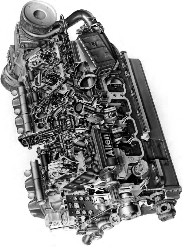
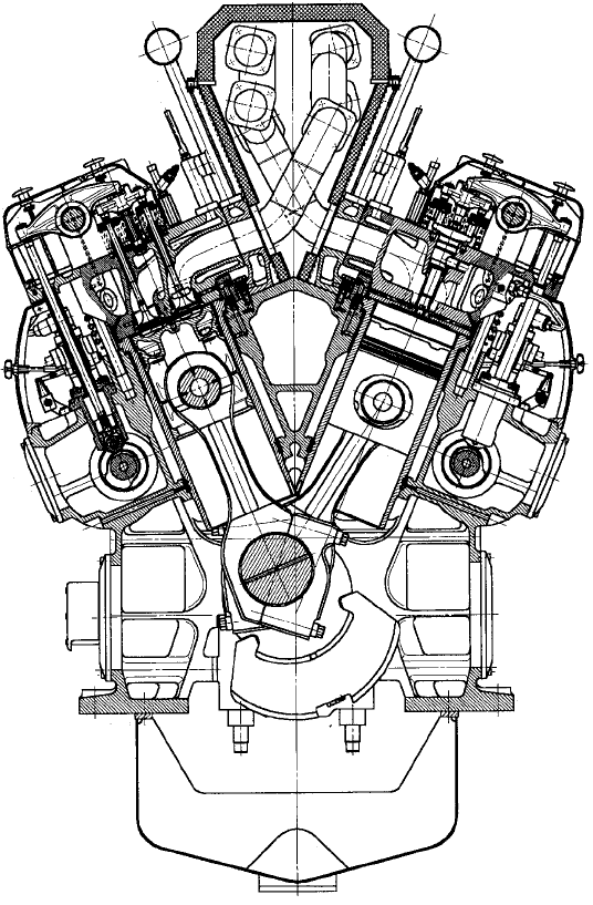
FiguRe 17.1 Cutaway of Allen 12VS37g engine
The connecting rods are arranged in pairs, fitting side-by-side on the crank-
pins. Each rod has a detachable cap secured by four set-screws and located by
dowels; the joint is inclined at 45° to enable the rod to be withdrawn through
the cylinder bore. Steel shell bearings lined with lead–bronze and overlay plat-
ing are fitted at the big end; a steel-backed lead–bronze-lined bush is fitted at
the small end. Individual four-valve cylinder heads are secured to the crankcase
by four studs and hydraulically tensioned nuts. The two inlet and two exhaust
valves seat on renewable inserts in the head, those for exhaust service being
intensively cooled and sealed with Viton O-rings. The inlet valves are manu-
factured from EN 52 and the exhaust valves from Nimonic. Each valve has two
valve springs, a rotator fitted below them to ensure even-wear distribution. The
thick flame plate of the cylinder head is cooled by drilled water passages close
to the combustion face. A combined fuel pump/injector is fitted centrally in the
cylinder head, the fuel inlet and return connections being via drilled passages
in the cylinder head sealed by Viton O-rings (Figure 17.2).
A cast iron rocker housing supports the fulcrum for the fuel and valve
levers, encloses the valve gear and also forms the cylinder head water outlet
connection and a part of the water outlet main. An aluminium cover is fit-
ted over the rocker housing. Lubricating oil is fed to the fuel pump and valve
levers through hollow pushrods and is drained to the sump via an external pipe.
A drilled passage is provided in the cylinder head to allow an adaptor and indi-
cator cock to be fitted for performance checks.
Allen (Rolls-Royce) 527
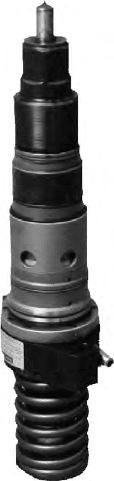
FiguRe 17.2 VS12 unit fuel pump/injector
528 Allen (Rolls-Royce)
The camshaft is built up from two-cylinder sections, each machined from a
solid forging and complete with two inlet valve, two exhaust valve and two fuel
pump cams. The sections are rigidly bolted together and registered by dowels
to ensure precise alignment. The finger-type cam followers are pivoted from a
central fulcrum shaft. Lubricating oil flows from each camshaft bearing into
the fulcrum through a drilled hole in the follower lever and then to the hollow
pushrod. An oil spray from the lever lubricates the roller and pin.
The cast aluminium housing encloses the camshaft and cam followers, and
also carries brackets for the two control shafts. The cover on the housing incor-
porates a heat shield.
A unit fuel pump injector with removable nozzle is arranged in each cyl-
inder head and operated from the camshaft by the fuel cam via cam follower,
pushrod and lever in a similar manner to the inlet and exhaust valves. It is sealed
into the head by four O-rings. An engine-driven fuel-pressurizing pump supplies
fuel via a filter to the fuel supply main and is controlled conventionally using an
electronic governor and electric actuator. A relief valve in the fuel return main
regulates the system pressure, with excess fuel returning to the pump suction.
Engine lubrication is effected by a wet sump system. A gear-type lubricat-
ing oil pump, mounted on the gearcase and driven from the crankshaft gear-
wheel, draws oil from the sump through a filter strainer. A relief valve on the
pump delivery safeguards the system against excessive pressure. Oil under
pressure is cooled and filtered before being fed into oil mains bolted to the
sides of the crankcase. The mains supply oil to the piston cooling jets and to
crankcase drillings feeding the crankshaft and camshaft bearings and the inter-
mediate gear.
External pipes supply oil to the turbochargers, water pumps and intermedi-
ate gears mounted in the gearcase. The oil filters are of the replaceable cartridge
type. A motor-driven priming pump is incorporated in the system to ensure that
all parts are supplied with oil before the engine is started ((Figure 17.3)..
Cooling water from the primary system circulates through the engine jack-
ets, turbochargers and heat exchanger or radiator. A secondary water system
supplies the charge air coolers and lubricating oil cooler. Primary and second-
ary water pumps are gear driven from an auxiliary gear train connected to the
camshaft by a quill shaft.
Each cylinder bank is served by its own turbocharger, charge air cooler
and inlet and exhaust manifolds. The turbocharger compressor discharges via
the air shut-off butterfly valve into the air inlet manifold through the charge
air cooler. A single exhaust manifold leads to the turbocharger inlet, and a
restricting throat is incorporated in the exhaust branch at each cylinder head.
Bellows units and V-clamps connect the individual exhaust branches to form
the exhaust manifold.
Engine effected by a compressed air-powered starter motor which engages
automatically with the gear ring on the flywheel. An electronic governor is fit-
ted, the standard system including a crankshaft speed-sensing pick-up installed
near the flywheel gear ring, a control box mounted off-engine, and an actuator
unit mounted on the engine gearcase connected through a collapsible link to
the fuel injection pump control shaft. A stop/run handle is connected to the fuel
control shafts to ensure that manual shutdown is always possible. The levers
operating the control racks of the unit injectors are spring loaded so that an
engine can always be shut down even if a control rack should stick.
Overspeed protection on the engine comprises two air shut-off butterfly
valves fitted between each turbocharger compressor discharge and air mani-
fold. The valves close on overspeed and cut off the combustion air supply to
the engine. They are held in the open (running) position by an air-operated
actuator equipped with a spring return arranged to close when the air supply
is lost. The air supply is fed via a solenoid valve energized to pass air to the
butterfly actuators. The solenoid valve is fed from a 24 V dc supply control-
led by an Amot speed monitor, which takes its speed signal from the magnetic
pick-up mounted over the engine flywheel gear ring. Other contacts in the
speed monitor are connected to the electronic governor so that the actuator also
moves to zero fuel on overspeed. The overspeed trip is set to operate when the
engine speed reaches 15 per cent above normal.
Explosion relief valves are fitted to the crankcase to relieve any build-up
of excess pressure inside the engine; they are also designed to prevent the
admission of air. The valves open if crankcase pressure rises, and the oil mist
mixture directed to atmosphere via a flame trap and deflector cowl. As soon as
the crankcase pressure returns to normal a coil spring closes the valve.
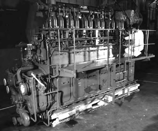
FiguRe 17.3 Allen S12 engine in-line cylinder form
Allen (Rolls-Royce) 529
531
C h a p t e r | e i g h t e e n
Alpha Diesel
(MAN Diesel)
From their introduction in the early 1970s, MAN B&W Alpha Diesel’s kin-
dred 23- and 28-type medium-speed engines were refined and uprated a
number of times to address changing requirements from small-ship propulsion
and genset drive markets. Upgradings by the Frederikshavn, Denmark-based
member of the MAN Diesel group tapped extensive service experience with
both designs which respectively featured 225/300 mm and 280/320 mm bore/
stroke dimensions. The last 28/32A engine programme covered a power range
from 1470 kW to 3920 kW at 775 rev/min with in-line 6- to V16-cylinder mod-
els, optimized for service intervals of 24–30 months based on an annual run-
ning time of 6000–7000 h. Outputs from 800 kW to 1920 kW at 825 rev/min
or 900 rev/min were developed by 6L, 8L and V12-cylinder variants of the
23/30A series.
Early experience with small medium-speed engines burning heavy fuel oil
found that exhaust valves could function for around 2000 h (although often
less) and had to be scrapped after 3000 h of service. In a few engines, whose
fuel was less aggressive and the load moderate, the interval could be extended
to 6000 h. Generally, however, the valve’s lifetimes were considered too short
in relation to the cost savings made from using heavy fuel and owners opted
for marine diesel oil instead.
Subsequent 28/32A engine developments raised the maintenance interval
to at least 15 000 h, representing a time-between-overhaul of 2 years. Operation
on heavy fuel was thus cost-effective for almost all ships, according to the
designer, the exceptions being tonnage whose load profiles dictated frequent
starting and stopping and low annual running hours.
Advances in performance were sought over the years along with improve-
ments in durability and reliability. The specific power rating rose by almost 40
per cent while the brake mean effective pressure remained at around 19 bar and
the specific fuel consumption at 190 g/kW h.
The general design features of the last 28/32A engine dated from 1990. The
engine’s overall appearance was much the same as it was when launched in
1974, with closed-in fuel piping and pumps. But the cross-section (Figure 18.1)
532 Alpha Diesel (MAN Diesel)
shows that many of the key elements—such as the frame, cylinder liner, piston,
cylinder cover and valves—were improved.
FrAMe
The frame was reinforced and cast in nodular cast iron. The support and cool-
ing of the cylinder liner were improved, and the staybolts for the cylinder head
given a deeper and enhanced grip in the frame to carry the load from higher
combustion pressures.
Figure 18.1 Cross-section of MAN B&W Alpha V28/32A engine
CoMBustioN
Contributions to reduced fuel consumption and lower exhaust gas emissions
were made by (a) accurate start of fuel injection timing, (b) precision-made
injection nozzles, (c) fuel pumps with precise fuel metering, (d) modified com-
bustion chambers yielding a compression ratio of 13.9, (e) precisely defined
fuel spray geometry and (f) increased injection pressure. Also influential was
the MAN B&W turbocharger, introduced in the 1980s and matched to the
28/32A engine.
Fuel VAlVes AND puMps
Good interaction between the engine and its fuel injection system determined
the engine’s torque and power output as well as its emissions and noise gen-
eration. Single-plunger injection operated with fuels of diverse viscosities and
with peak pressures up to around 1100 bar. The plunger and barrel assembly
was provided with a leakage oil return and an extra oil block for leaked fuel.
A ring-shaped groove was machined into the pump barrel. Lube oil was forced
into the fuel pump housing at the pump foot, preventing the spring guide from
sticking in asphaltenes. The very small leakage quantity involved was drawn
off through a separate outlet and led into a collecting tank.
CoMBustioN ChAMBer
Development of the 28/32A engine during 1988/1990 yielded an improved
combustion chamber in which the fuel spray mixed better with the air and
avoided spraying at the valves and piston top. In combination with an adjust-
ment of the pressures, the combustion process fostered reduced fuel consump-
tion and lower exhaust gas temperatures, along with minimized exhaust smoke.
CyliNDer heAD, VAlVes AND DuCts
Nodular cast iron was specified for the cylinder head to secure high strength
and stiffness. The head featured a bore-cooled flame deck and was fitted with
four rotating valves and cooled valve seats. Air and gas ducts were dimen-
sioned to ensure minimum resistance to an optimized air flow and to achieve
exhaust valve temperatures of below 400°C. Overhaul intervals exceeding
18 000 h on heavy fuel oil were confirmed in service. The performance of valves
and seats was closely monitored. Well-cooled seats, a rotating mechanism and
the construction material mean that it is not the valves that dictate the time for
maintenance. Regrinding can be carried out twice to give a valve lifetime of up
to 40 000 h (but sometimes shorter if the exhaust gases have attacked the valve
stem with sulphuric acid).
CyliNDer liNer
The liner is centrifugally cast from fine-grained perlitic iron. The improved
combustion chamber made it possible to introduce a step in the bore diameter
at the top of the cylinder with an uncooled flame ring. The inside diameter of
Cylinder liner 533
534 Alpha Diesel (MAN Diesel)
the ring is somewhat smaller than the liner bore. The piston crown is therefore
made correspondingly smaller, allowing carbon coke on the piston top to be
kept well clear of the running surface of the cylinder liner. The flame ring—
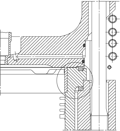
introduced on all new engines from 1992—has proved to be beneficial (Figure
18.2). It avoids liner polishing and micro-seizure, and helps to maintain the
piston rings in a good condition; a sound seal against the gas and combustion
forces results in a low and stable lube oil consumption.
pistoN
There were two suppliers of pistons for the 28/32A engine. The designs are
different but have both generally performed well. One type is a monobloc
piston of nodular cast iron with a splash-cooled piston top and a thin-walled
skirt to keep the weight down. The other type is a composite piston with a
steel top and a nodular cast iron skirt. Each has an intensively cooled top to
keep the rings in good condition and foster a low wear rate. The ring grooves
in the pistons are hardened and ground. The top piston ring was a focus of
development, the aim being to find the best compromise between low lube oil
consumption and good lubrication. All the rings have a chrome layer on the
running surface.
Figure 18.2 section through 28/32A cylinder, highlighting the ame ring