Woodyard D. (ed.) Pounders Marine diesel engines and Gas Turbines
Подождите немного. Документ загружается.

842 Gas Turbines
Certain aero engines are already fitted with power turbines and termed
turbo-prop or turbo-shaft machines; these are readily adaptable to industrial
and marine use. Special technical and production techniques are applied to the
redesigned gas turbine to ensure its suitability for sea level operation at high
powers and for the marine environment.
A basic gas generator has one rotating assembly: the compressor and its
turbine coupled together. The characteristics of axial-flow compressors vary
considerably, however, over the operating range from starting to full power. On
some high-compression ratio compressors it is necessary to fit automatic blow-
off valves and to alter the angle of the inlet guide vanes and first stages of sta-
tor blades to ensure efficient operation.
To achieve the necessary stability in larger gas generators, the compressor
is divided into two separate units: the LP and HP compressors, each driven
by its own turbine through co-axial shafts. Each compressor is able to oper-
ate at its own optimum speed, giving flexibility of operation and efficient
compression throughout the running range. Only the HP rotor needs to be turned
during starting, and therefore even the largest gas generator can be started
by battery.
Although such a two-spool compressor is very flexible, it is still necessary
in some cases to adjust the inlet guide vanes to deal with the changing flow of
air entering the compressor. This is effected automatically by pressure sensors
acting upon rams which alter the angle of the guide vanes.
An axial-flow compressor consisting of alternate rows of fixed and rotating
blades draws in atmospheric air through an air intake and forces it through a
convergent duct formed by the compressor casing into an intermediate casing,
where the compressed air is divided into separate flows for combustion and cool-
ing purposes. A typical annular combustion chamber receives about 20 per cent
of the air flow for combustion into which fuel is injected and burned.
Initial ignition is executed by electrical igniters, which are switched off
when combustion becomes self-sustaining. The resulting expanded gas is cooled
by the remainder of the air flow which enters the combustion chamber via slots
and holes to reduce the temperature to an acceptable level for entry into the one
or more axial-flow stages of the turbine. The turbine drives the compressor, to
which it is directly coupled. The remaining high-velocity gases are exhausted
and are available for use in the power turbine.
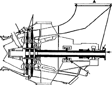
A power turbine of the correct ‘swallowing’ capacity is required to convert
the gas flow into shaft power (Figure 31.10). Typically of one or more axial-
flow stages, the power turbine may be arranged separately on a base frame
designed to mount the gas generator, to which the turbine is linked by a bel-
lows joint to avoid the need for very accurate alignment and to allow for dif-
ferential expansion. In some cases, however, expansion is allowed for in the
design of the power turbine and the gas generator is mounted directly on to
the inter-turbine duct. The power turbine, usually designed to last the life of
the plant, is surrounded by an exhaust volute which passes the final exhaust to
atmosphere through a stack.
Most marine gas turbines incorporate a free power turbine, which is free
to rotate at whatever speed is dictated by the combination of the power output
of the gas turbine change unit (GTCU) and the drive train behind it. The gas
turbine is designed so that there are no critical speeds in the running range, and
it can operate continuously with the power turbine at any speed from stopped
to the full power revolutions per minute of the power turbine. This facility is
especially important under manoeuvring conditions where the combination of
a free power turbine and reversing waterjets provides a flexible and effective
propulsion system.
Aero- and industrial-derived marine gas turbines are available with unit
outputs ranging from around 2000 kW to over 50 000 kW. Only the larger
designs (with ratings of 17 000 kW upwards) are reviewed here.
siemens
Lower operating costs through burning cheaper fuels than the light gas and
diesel oils normally required by aero-derived gas turbines are promised by
Siemens, which inherited the lightweight industrial-based turbine interests of
Swedish designer ABB Stal from Alstom Power in 2003. Successful marine
service experience on IF30 intermediate fuel is cited for the SGT-500 (for-
merly designated GT35) gas turbine, supported by a capability to burn IF180
fuel demonstrated in land-based plants.
The GT35 emerged from a post-war aero engine development programme
in Sweden involving Stal Laval and Volvo Flygmotor. Small turbojets were
designed and built for testing in the late 1940s/early 1950s but never entered
commercial production. Stal Laval saw potential in transforming the engine
into an industrial gas turbine for power generation and mechanical drive duties.
The first GT35, rated at 9000 kW, was tested in 1955 and installed during the
following year in a Swedish power station.
Performance and reliability were subsequently demonstrated in land-based
and offshore platform power generating installations. The design has since
Marine gas turbine designs 843
Inter-turbine duct
double-skinned
casing for cooling
Rotor blades with
minimum tip
clearances
Exhaust
Rotor not
torque limited
Output flange
Clockwise or
anti-clockwise
rotation
Hydrodynamic bearings
for long life
fiGure 31.10 Power turbine of a rolls-royce spey sM1C engine
844 Gas Turbines
benefited from two upgradings to attain its present output rating of 17 300 kW at
3450 rev/min for mechanical drive applications, with an efficiency of 33 per cent
(Figure 31.11).
The gas generator of the GT35 is a two-shaft engine equipped with a 10-
stage LP compressor, an eight-stage HP compressor, seven can-type combus-
tion chambers, a single-stage HP turbine and a two-stage LP turbine (Figure
31.12). The power turbine, developed in parallel with the gas generator, is a
three-stage design. A refinement made in the 1990s enabled the power turbine
to operate at variable speed and enhanced its suitability for mechanical drive
and marine applications.
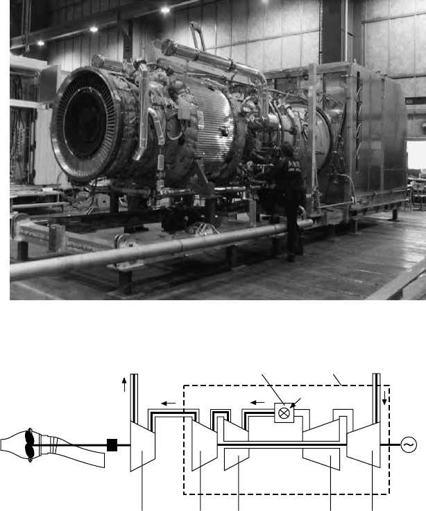
fiGure 31.11 one of two 17 000 kW abb stal GT35 (now designated siemens sGT-
500) gas turbines supplied to drive the waterjets of a stena Hss 900-class fast ferry
Combustion chambers Gas generator
Air
Fuel
850°C
Auxiliary
generato
r
5600 rpm
LPHP
Compressors
12.5 bar(a)
7000 rpm
HPLP
Turbines
Power
turbine
3300 rpm
Waterjet
Gear
93.5 kg/s
375°C
Flow diagram GT35 – Marine
fiGure 31.12 flow diagram of abb stal GT35 (now designated siemens sGT-500)
gas turbine in a marine propulsion installation
Refining the GT35 for marine applications called for the following meas-
ures: modifying the lube oil system to allow for vessel movements; modifying
the support arrangement to protect the turbine from hull deflections; and modi-
fying the power turbine by introducing a second combined journal and thrust
bearing, as well as a modified active tip clearance control mechanism (achiev-
ing a self-supported power turbine and thus eliminating the need for a thrust
bearing in the gearbox).
High reliability from the marinized GT35 was sought by exploiting as
many standard components as possible from the power generation and mechan-
ical drive versions. An extensive re-calculation of low-cycle fatigue and creep
properties of certain critical elements of the turbine was also undertaken, lead-
ing to subsequent redesign of some parts. High availability and maintainability
in arduous marine duty were addressed by adapting the installation to the spe-
cific vessel, with the aim of reducing the time for unit replacement and facili-
tating servicing. The maintenance programme was also adapted to operating
conditions imposing only short shutdown times for routine inspections and unit
change-outs.
Four key factors contribute to high fuel flexibility, underwriting operation
of a GT35 turbine set on IF30 fuel (normally produced from 75 per cent IF180
fuel/25 per cent marine gas oil) after suitable treatment:
l A high-viscosity tolerance due to the spill flow fuel system in which
the amount of fuel injected into the turbine is governed by a regulating
valve mounted in the return pipe from the injectors. The system configu-
ration makes it possible to circulate the fuel through the injectors prior
to ignition and hence warm them up sufficiently to facilitate starting on
fuels with a viscosity of up to 30 cSt/50°C (equivalent approximately to
10 cSt/95°C, the temperature to which the fuel is heated on the vessel).
l A maximum inlet temperature of 880°C (fairly low compared with other
gas turbine designs) makes it unnecessary to use cooled blades and
vanes, yielding such benefits as insensitivity to high-temperature cor-
rosion from sodium sulphate; no need for blade coating; and no risk of
plugging cooling holes and channels with ash deposits and reducing the
lifetime of blading.
l Large combustion chambers (Figure 31.13) secure low sensitivity to
variation in radiation heat depending on the type of fuel that is burned.
The size and design of the chambers ensure their lifetime matches that
of the complete turbine unit.
l A simple online ‘soft blast’ turbine cleaning procedure—with ground
nutshells injected directly into the turbine section via inspection win-
dows in the combustion chambers—results in sustained high turbine
efficiency and power output combined with low-outage time for clean-
ing. Cleaning can be effected with the turbine operating at close to full
load; depending on the fuel properties, the procedure is necessary at
intervals varying between 50 h and several months’ operation.
Marine gas turbine designs 845
846 Gas Turbines
Retaining a high output-to-weight ratio dictated special attention to the
marine GT35’s auxiliary systems, the designers reportedly achieving a reduc-
tion in weight of approximately 25 per cent over a land-based unit. Among
the measures was a redesign of the starting system from a pneumatic to an
electric system and a reconfigured base frame. Quiet running and high safety
are fostered by solid turbine casings which allow sets to be installed without
an enclosure. Packages can thus be better tailored to individual hulls, while
the free-standing auxiliary systems can be located in the most convenient
position.
Tests at Siemens’ Finspong facility in Sweden aimed to determine the
limits for good combustion when using commercially available heavy fuel
oil, with regard to viscosity and carbon residue. The fuel system was modi-
fied (pressurized since it would be subjected to heating in excess of 100°C) to
accept higher viscosity fuels. All the test targets were achieved and, in some
cases, exceeded. Operation was problem free and combustion efficiency high,
with no significant effect on turbine maintenance indicated. Furthermore, no
visible smoke was emitted down to loads below 20 per cent maximum rating.
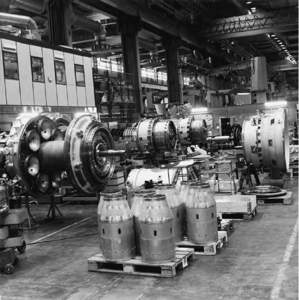
fiGure 31.13 seven large can-type combustion chambers (foreground) contribute
to the lower grade fuel burning capability of the abb stal GT35 (now designated
siemens sGT-500) gas turbine

After reviewing the results of heavy fuel operation, classification soci-
ety DNV signed a statement of preliminary approval that made the SGT-500
(formerly GT35) the only industrial gas turbine offered for marine applica-
tions burning such fuel. The following ISO 8217 marine fuels can be handled:
DMX, DMA, DMB, DMC, RMA 30, RMB 30, RMD 80, RMG 180, RMF
180 and RMG 380. Siemens also reports a seamless transfer between gas and
liquid fuels and the capability to run on virtually any combination of liquid
and gas.
Since acquiring the former Alstom Power portfolio, Siemens has supplied
dual-fuel SGT-500 sets for offshore floating production storage offloading
(FPSO) vessels.
General electric
General Electric (GE) introduced its first aero-derivative gas turbine, the
LM100, in 1959 and in the same year the LM1500, derived from the success-
ful J79 aircraft engine. The first LM1500 installation, serving the hydrofoil
vessel H.S. Denison, was followed by over 160 applications in land-based cata-
pults, pipeline pumping systems, marine propulsion and power generation. The
mainstay of the US designer’s programme, the LM2500, arrived in 1969 and
has since benefited from developments which have doubled its initial rating of
around 15 000 kW. Other models subsequently joined the LM-series portfolio,
which now embraces six simple-cycle designs with maximum power ratings
from around 4500 kW to 42 750 kW and thermal efficiencies up to 42 per cent.
Valuable experience from LM-series gas turbines in naval propulsion appli-
cations ranging from patrol craft to aircraft carriers was tapped by GE Marine
Engines in targeting commercial vessel projects during the 1990s, earning a
number of large cruise ship and fast ferry references.
GE Marine Engines’ aero-derived LM gas turbine family
Model Maximum Rating Thermal Eciency
lM500 4470 kW 32 per cent
lM1600 14 920 kW 36.7 per cent
lM2500 25 060 kW 37.1 per cent
lM2500 30 200 kW 39 per cent
lM2500G4 35 300 kW 41.3 per cent
lM6000 42 750 kW 42 per cent
The LM500 is a two-shaft gas turbine derived from GE’s TF34 aircraft
engine; the LM1600 is a three-shaft gas turbine derived from the F404 engine;
and the LM6000 is a two-shaft gas turbine derived from the CF6-80C2 engine.
The most successful models in the commercial and military marine markets are
the LM2500 and LM2500 models, described in the next section.
Marine gas turbine designs 847
848 Gas Turbines
lM2500 anD lM2500
Derived from the GE military TF39 and commercial turbofan aircraft engines,
the LM2500 marine gas turbine is a simple-cycle, two-shaft engine compris-
ing a gas generator, a power turbine, attached fuel and lube oil pumps, a fuel
control and speed-governing system, associated inlet and exhaust sections, lube
and scavenge systems, and controls and devices for starting and monitoring
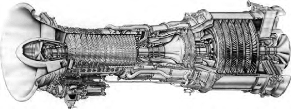
engine operation. The four main elements (Figure 31.14) are:
l A 16-stage compressor, with an 18:1 pressure ratio; the first seven stages
feature variable stators and inlet guide vanes promoting easy starting,
good part-load performance, high efficiency and a high stall margin over
the entire operating range.
l Fully annular combustor, with externally mounted fuel nozzles sup-
porting liquid fuel combustion; virtually smokeless operation is assured
through the complete power range even when burning heavy distillate
fuels.
l Two-stage HP turbine, air-cooled for a long life, which drives the com-
pressor and accessory-drive gearbox.
l Six-stage LP power turbine; a low-speed, low-stress machine aerody-
namically coupled to the gas generator and driven by its high energy
release exhaust flow.
Lower installed and life-cycle costs per unit kilowatt were sought from the
LM2500 derivative released in the late 1990s with a 25 per cent higher power
rating than its precursor. An introductory rating of 27 600 kW was achieved
with a thermal efficiency of more than 37 per cent; release at the design rat-
ing of 29 000 kW and a thermal efficiency of 38 per cent followed early sets in
service demonstrating the traditional reliability and availability of the LM2500.
The current rating is 30 200 kW with a thermal efficiency of 39 per cent. The
design refinements applied to the LM2500 focused on:
– The compressor rotor: air flow was increased by approximately 20 per
cent; Stage 1 blades were redesigned to a wide chord configuration
fiGure 31.14 Cutaway of Ge Marine engines’ lM2500 aero-derived gas turbine
showing (from left to right) the compressor, annular combustor, HP turbine and lP
power turbine
eliminating the mid-span dampers; an LM6000 rotor airfoil design was
added to Stages 2 and 3; LM6000 stages were incorporated to improve
compressor efficiency; and a new inlet guide vane assembly was
specified.
– HP turbine rotor and stator: redesigned to reduce maintenance costs and
new materials exploited for improved oxidation life; Stage 1 and 2 con-
tours optimized for higher flows.
– Power turbine: redesigned in line with the higher output; Stage 1 and 6
blades optimized for aerodynamic efficiency; and the rotor strengthened
for the higher torque and potential energy.
No changes were made to either the standard or DLE combustion system.
Only slightly longer and heavier than the LM2500, the LM2500 offers
dual-fuel capability (distillate and gas), rapid start-up and loading, variable
speed operation and excellent part-load efficiency, GE claims.
lM2500G4
Further investment in the LM2500 gas turbine resulted in 2005/2006 in the
LM2500G4 derivative with a rating of 35 300 kW at ISO day conditions
and a thermal efficiency of 41.3 per cent. This fourth-generation design offers
17 per cent more power with a 6 per cent higher air flow than the established
LM2500 model.
Essentially an LM2500 with increased flow capacity in the HP compres-
sor, HP turbine and LP turbine, the G4 version has a pressure ratio of 24.2
compared with the original 23.6. Design changes were limited to minor blade
and stationary vane airfoil adjustments that provide the mass flow increase. HP
turbine modifications included minor blade-cooling improvements and proven
material upgrades from aircraft technology which enhance higher temperature
capability. The effective area of the compressor discharge pressure seal was
adjusted in order to maintain the optimum rotor thrust balance.
Structurally, all frames—such as front, compressor rear, turbine mid- and
rear frames—remained unchanged, as did the sump hardware and the number
of main shaft bearings. Among the internal changes benefiting the G4 model
were:
l Redesigned inlet guide vanes and re-staggered Stage 0 blisk airfoils.
l Increased HP compressor life design through rotor material changes.
l Redesigned Stage 1 HP turbine blade with improved cooling and oxida-
tion coating.
l Application of thermal barrier coatings to HP turbine Stage 1 nozzle.
l Material change and improved cooling for the Stage 2 nozzle.
l Redesigned Stage 2 HP turbine rotor for extended life.
l Redesigned Stages 2 and 3 nozzles for the six-stage low-speed (nominal
3600 rev/min) power turbine for increased output.
GE also offers a two-stage high-speed power turbine with a design speed of
6100 rev/min and an operating speed range of 3050 rev/min to 6400 rev/min for
General electric 849
850 Gas Turbines
mechanical drive and other applications where continuous shaft output speeds
of 6400 rev/min are desirable. Both six-stage and two-stage power turbines can
be operated over a cubic load curve for mechanical drive duties.
With a single annular combustor, the LM2500G4 has the same fuel flexi-
bility as the LM2500, allowing it to operate on natural gas, liquid fuel or dual
fuel. Water or steam injection can be adopted for NOx emission abatement.
Improvements in base load power over the LM2500 were focused across a
wide range of ambient conditions. Specifically, during off-ISO conditions, such
as cold day/hot day, the LM2500G4 yields an 11/12 per cent power increase.
In combined-cycle mode, it was expected to have 8.5 per cent power and
0.75 per cent heat rate advantages.
A naval propulsion debut for the LM2500G4 gas turbine was secured in
2006 from the FREMM frigate programme for the French and Italian navies.
Mitsubishi
A Japanese challenge in the aero-derived marine gas turbine market was
spurred by the country’s Techno-Superliner (TSL) fast freight carrier project of
the early 1990s which called for an indigenous high output prime mover with a
very low weight. In response, Mitsubishi created the MFT-8 from the marriage
of its own power turbine and the GG-8 gas generator from Turbo Power and
Marine Systems, a subsidiary of Pratt & Whitney (Figure 31.15).
The GG-8 is a land and marine derivative of the US group’s JT8D turbo-
fan aero engine, the design modified to replace the front fan with the forward
part of the front compressor; otherwise it is fully compatible with the core
engine. The key elements of the gas generator are: an eight-stage LP compres-
sor; seven-stage HP compressor; nine burner cans; a single-stage air-cooled HP
turbine; and a two-stage LP turbine. Gas is fed to a high-performance power
turbine developed by Mitsubishi’s project team as a three-stage design with
lightweight, overhung ball and roller bearings.
The main modules and components are designed for ease of removal and
replacement during inspection and maintenance; and provision is made for
borescope inspection of the hot parts and rotating parts of the gas generator
and power turbine without disassembly.
After the prototype achieved a full power rating of 24 300 kW during shop
trials, two production sets were delivered for installation in the TSL craft built
by Mitsubishi. The Japanese designer subsequently offered the MFT-8 turbine
to the wider market with a propulsion plant rating of 25 790 kW and a thermal
efficiency of just under 39 per cent.
rolls-royce
Marine sPey
The Marine Spey first went to sea with the UK Royal Navy in 1985, and the
latest C-rated version entered service in 1990. Numerous warship propulsion
references have been logged and commercial opportunities targeted, notably
for high-speed ferry and freight vessel projects (Figure 31.16). The twin-spool
design is released with respective commercial and military marine ratings of
18 000 kW and 19 500 kW, and sfcs of 230 g/kW h and 226 g/kW h.
Gas generator, power turbine and all ancillary systems are mounted on a
common bedplate to form a self-contained unit for ease of installation (Figure
31.17). Interfaces for the shipbuilder are limited to the intake and uptake
flanges, the mountings to the hull and the output flange. A complete propulsion
module, including power turbine, has a length of just over 7.5 m and weighs
17.5 tonnes in its commercial vessel configuration; the gas generator weighs
only 1.8 tonnes. An 80 per cent weight saving and 60 per cent space saving
over a medium-speed diesel installation of equivalent output are reported.
The gas generator is a high-efficiency, second-generation unit of twin-
spool design designated the SM1C, which is a development of the SM1A and
incorporates technology from the Rolls-Royce Tay and RB211 aero engines.
The core achieves a 20:1 pressure ratio and good overall efficiency from
a compact unit with relatively few stages of blading. The designers sought
rolls-royce 851
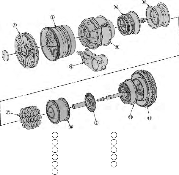
1 Compressor inlet
2 Front compressor
3 Compressor intermediate
4 Main accessory gearbox
5 Rear compressor
6 Diffuser
7 Combustion section
8 Turbine nozzle
9 Rear compressor drive turbine
10 Front compressor drive turbine
11 Exhaust case
fiGure 31.15 Major engine groups and sections of Mitsubishi MfT-8 aero-derived
marine gas turbine