Woodyard D. (ed.) Pounders Marine diesel engines and Gas Turbines
Подождите немного. Документ загружается.

852 Gas Turbines
excellent operational flexibility, rapid acceleration and good aerodynamic
stability, with no visible exhaust smoke at any power level. The modular con-
struction allows gas generator sections to be exchanged on site, the engine
comprising five maintenance assembly change units (MACUs).
Specifically designed for the marine environment, the power turbine is a
high-efficiency, two-stage axial-flow design with short and rugged shrouded
blades capable of withstanding significant foreign body damage. Its rotor sys-
tem is supported on hydrodynamic bearings housed in a rigid centre body, and
is available with clockwise or anti-clockwise output shaft rotation. The power
turbine is designed for the life of the ship but is removable in the event of seri-
ous damage (Figure 31.10).
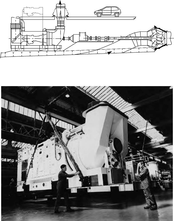
fiGure 31.16 rolls-royce Marine spey machinery arrangement for a waterjet-
powered fast ferry
fiGure 31.17 a fully packaged rolls-royce Marine spey propulsion module

Marine Spey data
Power, commercial service rating
18 000 kW
intake mass ow 64.3 kg/s
exhaust mass ow 65.5 kg/s
exhaust temperature 480°C
Compressor stages
lP 5
HP 11
Turbine stages
lP 2
HP 2
PT 2
shaft speeds lP 7900 rev/min
HP 12 000 rev/min
PT 5000 rev/min
Combustion system Cannular 10 combustors
number of shafts 2free power turbine
MT30
A simple-cycle marine gas turbine with a thermal efficiency exceeding 40 per
cent, the Rolls-Royce Marine Trent 30 was scheduled for commercial availa-
bility from early 2004 offering outputs up to 36 000 kW from a package weight
of 25 tonnes. The MT30 is the eleventh engine type derived from the British
designer’s core aero technology (Figure 31.19) and has gained references in
UK Royal Navy and US Navy projects.
The aero Trent 800 was selected from a diverse Rolls-Royce engine
family as the parent for this new generation of marine gas turbine because
it best matched current and emerging customer requirements with margins
in hand. The three-spool marine derivative allows variable speed operation,
and its ‘turn-down’ facility secures low-power harbour manoeuvring capa-
bility. Furthermore, the aero engine’s track record (99.9 per cent dispatch
reliability) gave confidence for commercial marine applications with high
annual usage.
Availability, reliability and maintainability were prime goals in setting the
design parameters for the MT30, with an overhaul target of 12 000 h for the
hot end and 24 000 h between major overhauls. The design reportedly features
some 50–60 per cent fewer parts than other aero-derived turbines in its class.
A sound basis is provided by an 80 per cent commonality of parts with the
aero Trent. Specialized coatings are applied where necessary for protection
against the marine environment. Internal temperatures and pressures are sub-
stantially lower than those at the aero engine take-off rating to foster compo-
nent longevity.
rolls-royce 853
854 Gas Turbines
A rating of 36 000 kW is available at the power turbine output shaft at ambi-
ent air temperatures up to 26°C, with a corresponding sfc of 207 g/kW h; under
tropical conditions (32°C air temperature) the output is 34 100 kW. Competitive
efficiency is sustained down to 25 000 kW and thermal efficiency is similar to
that of high-speed diesel engines, Rolls-Royce claims. The MT30 is designed
to burn the widely available distillate marine fuel-grade DMA.
Essentially the core unit of an aero Trent engine minus the fan section, the gas
generator of the MT30 benefited from the latest design techniques, materials and
production technology during its refinement for marine applications. An eight-
stage variable geometry axial intermediate pressure (IP) compressor driven by a
single-stage IP turbine feeds air to the HP spool, which comprises a six-stage
compressor and a single-stage HP turbine. An annular combustion chamber is
arranged between the HP compressor and the HP turbine. The IP and HP spools
rotate in opposite directions. A two-spool compressor design yields reduced start
time, good balance retention and no lock-up problems, says Rolls-Royce, result-
ing in greater operational flexibility and no need for in-situ balancing.
Hot gas from the gas generator section is supplied to a four-stage free
power turbine whose full speed of 3300 rev/min was selected for mechanical
drives to yield the lowest sfc. The design addresses the demands of waterjet
operation, notably sudden large load changes if air is drawn into the jet unit in
severe sea conditions.
The MT30 is supplied as a package with an acoustic enclosure housing aux-
iliaries and inlet and exhaust diffusers, and incorporating automatic fire detec-
tion and extinguishing systems (Figure 31.18). A complete unit—measuring
9.1 m long 3.8 m wide 4 m high—weighs around 22 tonnes dry, depending
on the options selected. The GTCU, including power turbine, weighs 6200 kg
dry and is air-freightable. Installation of the main package can be effected in a
single lift at the shipyard, while the control panel, starter and lube oil modules
can be mounted where convenient in the engineroom (Figure 31.19).
A key element of the package—the integrated control and monitoring system—
is housed in a free-standing cabinet with an uninterrupted power supply for pro-
tection in the event of mains failure. An engine health monitoring system is also
offered. Condition-based maintenance is facilitated by internal condition sen-
sors; routine servicing is limited to checking fluid levels and visual examina-
tions. Maintenance contracts covering servicing, overhauls and spares supply,
long practised in the airline industry, are available to support operators and foster
competitive through-life costs.
Wr-21
The only advanced-cycle marine gas turbine currently on the market, the WR-21
was developed by Northrop Grumman in the USA and Rolls-Royce during the
1990s with funding from the US Navy, UK Royal Navy and French Navy. It is the
first aero-derived gas turbine to incorporate compressor intercooling and exhaust
heat recuperation (Figure 31.20) to foster a low sfc across the operating range: a
fuel burn reduction up to 30 per cent over simple-cycle turbines is reported.
rolls-royce 855
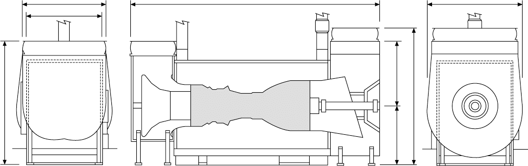
fiGure 31.18 rolls-royce MT30 in mechanical drive package (dimensions in millimetres)
3482
2942
4537
Gas turbine
Gas turbine enclosure
Air
intake
9174
Exhaust
duct
2169
5028
2359
3837

856 Gas Turbines
Rated at 25 000 kW, the WR-21 is based on the successful Rolls-Royce aero
RB211 and Trent engines, with modifications to marinize the components and
effectively integrate the heat exchangers and variable geometry. The first sea-
going installations (featuring twin sets) entered service from 2008 in the UK
Royal Navy’s new Type 45 class destroyers—a series of six headed by HMS
Daring—but commercial propulsion opportunities, particularly cruise ships, are
also targeted. The fuel consumption characteristics—approximately 205 g/kW h
MT30 gas turbine data
Power
36 000 kW @ 25°C ambient
30 000 kW @ 35°C ambient
specic fuel consumption 207 g/kW h
exhaust mass ow 113 kg/s
exhaust temperature 466°C
Compressor stages
iPC–8
HP–6
Turbine stages
iP–1
HP–1
Power turbine stages PT–4
Power turbine shaft speed
3600 rev/min
fiGure 31.19 rolls-royce MT30 gas turbine
from full power down to around 30 per cent power—enable the WR-21 to fulfil
the role of both cruise and boost engines.
Compared with simple-cycle turbines, the benefits cited for the WR-21
include an improvement in fuel efficiency over the entire operating range (with
a radical improvement at low power), easier maintenance through enhanced
modularization and the facility to retrofit ultra low-emission reduction systems.
The ICR propulsion system package was designed to occupy the same foot-
print as existing power plant (Figure 31.21).
A significant fuel saving over simple-cycle turbines is achieved by using
heat exchangers to improve the part-load cycle efficiency. Recuperation alone
improves the thermal efficiency of LP ratio cycles where the exhaust temperature
of the turbine is significantly higher than that of the air leaving the compressor.
Heat is transferred to the compressed air before it enters the combustion system,
reducing the amount of fuel required to attain the cycle turbine entry temperature.
rolls-royce 857
Exhaust
30–40%
Reduction in fuel
consumption
* Van
Propeller
Reduction
gearbox
Power
turbine S1030/3
Recuperator
*
*
LP
turbine
HP
turbine
FuelHP
Compressor
LP
Compressor
Air inlet
Dump
valve
Intercooler
Water
25% Power increase
Bypass valve
Combuster
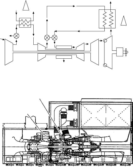
fiGure 31.20 iCr system applied to the rolls-royce Wr-21 gas turbine
Combustor
Intercooler
Intake
Recuperator
fiGure 31.21 layout of Wr-21 gas turbine package
858 Gas Turbines
The recuperator thus preheats the combustion air by recovering waste
energy from the exhaust, improving cycle efficiency and reducing fuel con-
sumption. Low-power efficiency is improved still further by power turbine
variable area nozzles (VAN); these maintain a constant power turbine entry
temperature, which in turn maintains recuperator gas side entry conditions and
improves recuperator effectiveness as power reduces.
The intercooler cools air entering the HP compressor, reducing the work
required to compress the air; the intercooler also reduces the HP compressor
discharge temperature, which increases the effectiveness of the recuperator.
Air enters the compressors via a composite radial intake designed to main-
tain uniform circumferential velocity at entry to the gas generator. The IP com-
pressor (so called because it reflects commonality with the parent three-spool
turbofan aero engine) includes six stages of compression; stages two to six are
in common with the RB211 engine, while the first stage is modified to suit the
increased flow requirements of the ICR cycle.
The intercase between the compressors transmits structural load from the
engine through two support legs to the sub-base; it also houses the five inter-
cooler segments in an outer casing and the internal gearbox within an inner cas-
ing. Both casings combine to form the air flow path between compression stages.
Incorporating an intercooler between the compression stages on a twin-spool
cycle increases the specific power of the engine. The amount of work needed
to drive the compressor is reduced, thereby increasing the net power available.
Bypass valves on the intercooler are modulated depending on the pressure and
relative humidity of the air so that condensation formation can be avoided.
Cycle thermal efficiency is approximately the same as that of a simple-
cycle engine, as additional fuel is required to offset the drop in compressor exit
temperature. Combining an intercooler with a recuperator, however, is attrac-
tive for higher pressure ratio engines, leading to high specific power outputs
and good thermal efficiency.
The HP compressor also has six compression stages and is aerodynami-
cally identical to its aero origin. Compression is split 30:70 between IP and HP
compressors, and both stages incorporate additional borescope holes to allow
greater flexibility for inspection.
The Marine Spey SM1C combustor was adopted as the basis for the WR-21
combustor design as a proven system in use worldwide. Although otherwise
conventional in its construction, the combustor features a Reflex Airspray
Burner method of fuel injection developed specifically for the marine versions
of the Spey. This achieves a controlled mixing of fuel and air, allowing a high
burner exit air–fuel ratio (AFR) to be maintained with adequate flame stability.
Based on previous experience, high (lean) AFR was considered an important
factor in reducing visible smoke when burning diesel fuel.
Preservation of the proven aero RB211 HP and IP spool lengths, which are
characterized as short, rigid high-integrity structures, was a principal design
objective. The requirement to remove compressor delivery air and return recu-
perated air within the length constraint dictated that the annular RB211 com-
bustor be replaced by a radially orientated turbo-annular system.
The manifold designs underwent extensive analysis and testing to con-
firm structural integrity, aerodynamic flow distributions, ease of manufacture
and maintainability. The inner casing carries the structural load from the HP
compressor outer casing to the turbine casing; the component is designed so
that it provides the minimum of blockage for HP compressor exit air entering
the combustion manifold and also transfers HP compressor Stage 4 air to the
power turbine for sealing and cooling. In-situ removal of the combustor and
burner is a key element of the maintainability strategy. The design addresses
ease of life monitoring and timely repair or replacement of hardware (without
engine removal) in the event of premature failure.
The HP nozzle guide vanes and rotor blade airfoils maintain commonal-
ity with the RB211-524 parent engine, with slight modifications to provide a
smooth gas path from the radically swept discharge nozzles. The disc seals and
bearing arrangements are essentially unchanged from their aero origins. The IP
nozzle guide vane is skewed relative to the aero RB211-535 vane and incorpo-
rates the addition of a cast boss to facilitate a borescope inspection hole. The
blade is uncooled and manufactured from a single nimonic to extend creep life.
Consistent with the pedigree of the gas generator, the power turbine also
originates from an aero parent, the Trent. Stages two-through-five incorporate
three-dimensional orthogonal blade geometry to maximize turbine efficiency, but
the main difference is the incorporation of VANs which control flow area. The
VANs are hydraulically actuated via a single-geared ring designed to maintain
VAN-to-VAN throat areas within a specified tolerance. The VAN is fully open at
full power and closes at part power; this has the effect of retaining the efficiency
benefits across the whole power range by maintaining the high exhaust tempera-
ture at part powers. The recuperator can thus be exploited fully to give the char-
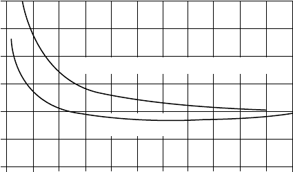
acteristic flat fuel consumption curve for the WR-21 (Figure 31.22).
The gas generator and power turbine comprise 12 interchangeable, pre-
balanced modules, whose small size and low weight facilitate removal via sim-
ple routes; new or leased modules can be fitted in-situ, reducing maintenance
costs and downtime.
rolls-royce 859
Typical simple cycle
WR21
0 20 40 60 80 100
% Power
1.2
1.0
0.8
0.6
0.4
0.2
0
SFC (lb/hp.h)
fiGure 31.22 fuel savings from iCr cycle Wr-21 gas turbine over the power range
compared with a simple-cycle unit
860 Gas Turbines
The enclosure panels are structurally designed to meet blast overpressure,
shock and air tightness, with insulation and acoustic damping treatment applied
to satisfy thermal and noise requirements. All the panels are removable, except
those welded to the recuperator housing. The engine can be withdrawn side-
ways by removing vertical supports at its front. The enclosure is cooled by
ship’s ventilation, air entering it via a connection above the recuperator ducts.
An electronic engine controller (EEC), incorporating a full authority dig-
ital engine control (FADEC) system, is responsible for controlling the system
in response to commands from either the ship’s monitoring and control sys-
tem or from the local man–machinery interface (MMI). The controller covers
sequencing, steady state and transient control, surveillance, fault detection and
protection.
Easy control of NOx emissions when entering controlled waters is fos-
tered by the flexibility of the ICR cycle. Punitive charges can be avoided by
switching to recuperator bypass mode, lowering the combustion temperature
beneath the threshold for NOx generation. Additionally, the high combustor
inlet temperatures over the power range in recuperated operation ensure com-
plete combustion with extremely low levels of carbon monoxide and unburned
hydrocarbons.
Gas Turbine MainTenanCe
Gas turbines have nominal power ratings established for marketing purposes.
A power rating at particular ambient conditions determines the internal engine
temperatures and the resulting expected service life of components exposed to
these temperatures. These ‘hot section’ components include the combustor and
the HP turbine blades and vanes. The life of the hot section components will
determine the interval between major maintenance actions, resulting in an esti-
mated average maintenance cost.
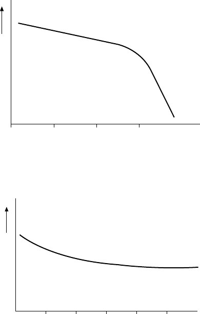
The normal relationship between internal parts life and a representative
internal gas turbine temperature, in this case the power turbine inlet tempera-
ture, is indicated in Figure 31.23. At higher internal temperatures the compo-
nent life is determined by creep-rupture and decreases rapidly with increased
temperature; at lower internal temperatures the component lives are determined
by corrosion and do not vary as rapidly. (Turbine blades operate at high tem-
perature and rotate at high speed. The blade material has an overall creep life
which is proportional to time at a given power level.)
The nature of the curve in the figure illustrates the selection of power rat-
ing for a particular application. Operation for large percentages of time at
power levels in the creep-rupture regime will severely limit component lives in
the gas turbine and increase the unit’s average maintenance cost. Conversely,
best advantage of a gas turbine’s capability can be taken with respect to main-
tenance near the top of the corrosion-controlled regime. Establishing a rating
around the ‘knee’ of the curve therefore tends to be a good starting point with
respect to trade-off between optimum power and reasonable maintenance costs.
Vessel operations will generally involve some representative profile with a
mixture of high- and low-power elements, and a range of ambient operating
temperatures. The optimized gas turbine rating makes best use of the engine at
the predominant mode of operation, while ensuring that the maintenance costs
combined with other operating costs produce a minimum total life-cycle cost.
A second factor affecting maintenance costs is the number of cycles of
operation per unit time. Since some internal components may be limited in life
to a maximum number of thermal cycles, operation with very short mission
lengths will result in higher average maintenance costs.
Figure 31.24 illustrates the nominal relationship of average maintenance
cost to length of mission. For example, a fast ferry operation with mission
lengths of 1 h will experience a higher average annual maintenance cost than for
5- or 6-h runs at the same power rating and ambient conditions. As the length of
the mission increases, the maintenance requirements approach the level deter-
mined by the power level and ambient conditions resulting from the hot section
life. For short missions, however, the replacement of cyclic-limited components
Gas turbine maintenance 861
Creep-rupture limited
Corrosion limited
10 100 1000 10000
Hot section refurbishment interval (hours)
Power turbine inlet temperature
fiGure 31.23 relationship between internal parts life and power turbine inlet
temperature
1 2 3 4 5
Average mission length (hours)
Average maintenance cost
($/hour)
fiGure 31.24 average gas turbine maintenance cost versus length of mission