Yu W., LaBoube R.A. Cold-Formed Steel Design
Подождите немного. Документ загружается.

SHELL ROOF STRUCTURES 335
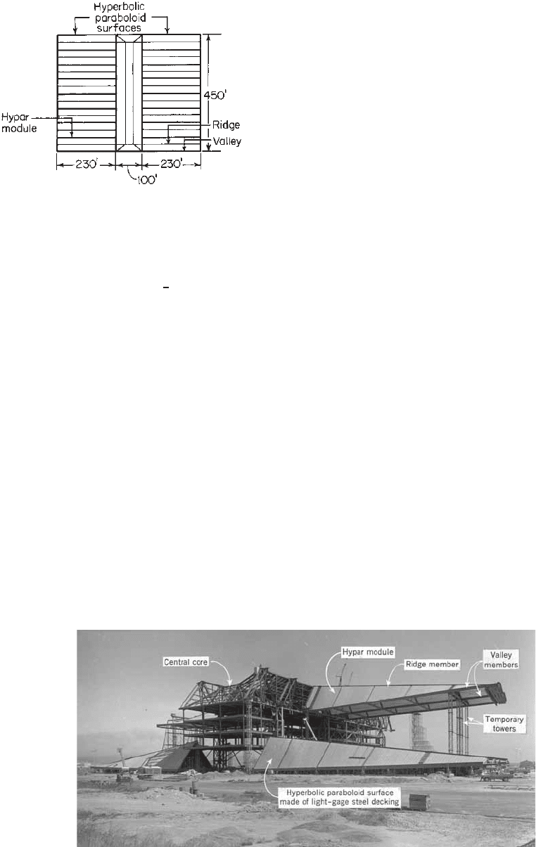
Figure 9.26 Roof plan of superbay hangar. (Courtesy of Lev
Zetlin Associates, Inc.)
1.82
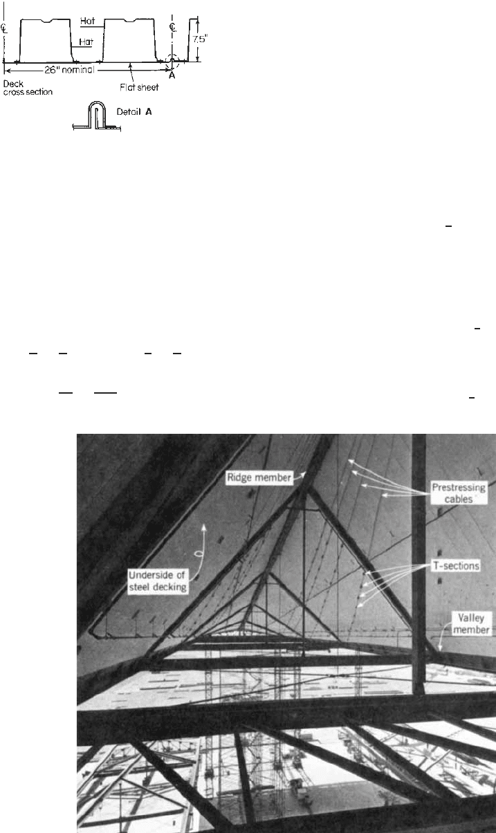
0.0934-in.- (2.4-mm-) thick sheet, 26 in. (660 mm) wide,
with two 9-in.- (229-mm-) wide by 7
1
2
-in.- (191-mm-) deep
0.0516-in.- (1.3-mm-) thick steel hat sections welded to the
flat sheets. Figure 9.28 shows a typical cross section of the
steel deck used.
In order to be able to use this type of structural system in
any area of the world, prestressed cables are incorporated
into the shell structures (Fig. 9.26). Since the structural
strand cables induce a prestress in the shell, the system is
readily adaptable to any geographic site.
A comparison of various types of designs indicate
that this type of building with its hyperbolic paraboloids
weighs approximately 40% less than a conventional steel
construction.
9.4.3.2 Types of Hyperbolic Paraboloid Roofs The
surface of a hyperbolic paraboloid may be defined by
two methods.
1.80
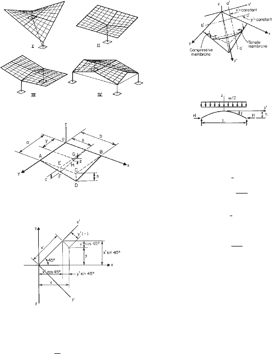
As shown in Fig. 9.29, with the x, y,
and z axes mutually perpendicular in space, the surface
is formulated by two straight lines called generators. One
line, parallel to the xz plane, rotates about and moves
along the y axis; the other, parallel to the yz plane, rotates
about and moves along the x axis. The intersection of the
generators is contained in the surface of the hyperbolic
paraboloid.
Figure 9.30 shows several types of hyperbolic paraboloid
roofs which may be modified or varied in other ways to
achieve a striking appearance.
In general, type I is the most pleasing of the shapes
available. The edge beams are in compression and are
usually tubular members. For this type of roof, the most
serious problem is the horizontal thrust at the supporting
columns. Usually the columns are kept short in order to
transfer the thrust down to the floor where tie rods can
be hidden. Four units of this type with a common center
column probably provide the most rigid roof structure, as
shown in Fig. 1.14.
Type II is an inverted umbrella, which is the easiest and
the least expensive to build. The edge members of this type
are in tension, and engineers usually use angles as edge
members.
Type III is the most useful type for canopy entrance
structures. The edge members connected to the columns are
in compression and are usually tubes, while the outside edge
members are in tension and could be angles or channels.
In some cases, one-half of the roof may be kept horizontal
and the other half tilts up.
Generally speaking, type IV is the most useful of all the
available shapes. The entire building can be covered with a
completely clear span. The horizontal ties between columns
on four sides can be incorporated in the wall construction.
9.4.3.3 Analysis and Design of Hyperbolic Paraboloid
Roofs The selection of the method of analysis of hyper-
bolic paraboloid roofs depends on the curvature of the shell
used. If the uniformly loaded shell is deep (i.e., when the
Figure 9.27 Construction of superbay hangar. (Courtesy of Lev Zetlin Associates, Inc.)
1.82
336 9 SHEAR DIAPHRAGMS AND ROOF STRUCTURES
Figure 9.28 Cross section of steel deck used in superbay hangar.
(Courtesy of Lev. Zetlin Associates, Inc.)
1.82
span–corner depression ratio a/h showninFig.9.24is
less than or equal to approximately 5.0), the membrane
theory may be used. For the cases of a deep shell subjected
to unsymmetrical loading and a shallow shell, the finite-
element method will provide accurate results.
9.80
In the membrane theory, the equation of the surface of
a hyperbolic paraboloid can be defined from Fig. 9.31.
Assume
h
c
=
b
x
and
c
z
=
a
y
(9.63)
z =
cy
a
=
hxy
ab
= kxy (9.64)
where k = h/ab, in which h is the amount of corner
depression of the surface having the horizontal projections
a and b.
If we rotate coordinate axes x and y by 45
◦
, as shown
in Fig. 9.32, the equations for two sets of parabolas can
be obtained in terms of the new coordinate system using x
and y
.
9.81
Substituting
x = x
cos 45
◦
− y
sin 45
◦
(9.65)
y = y
cos 45
◦
+ x
sin 45
◦
(9.66)
into Eq. (9.61), one can obtain a new equation for z in
terms of x
and y
,
z =
1
2
k[x
2
− y
2
] (9.67)
In Eq. (9.67), if the value of x
remains constant, as
represented by line a
–a
in Fig. 9.33, the equation for
the parabolic curve can be written as follows, where the
negative sign indicates concave downward:
z
=−
1
2
ky
2
(9.68)
When the value of y
remains constant, Eq. (9.66) can be
obtained for a concave upward parabola:
z
=
1
2
ky
2
(9.69)
Figure 9.29 Prestressed cables used in hangar roof. (Courtesy of Lev Zetlin Associates, Inc.)
1.82
SHELL ROOF STRUCTURES 337
Figure 9.30 Types of hyperbolic paraboloid roofs.
Figure 9.31 Dimensions used for defining the surface of hyper-
bolic paraboloid roof.
Figure 9.32 Coordinate system using x
and y
axes.
For a constant value of z, the hyperbolic curve can be
expressed by
2z
k
= x
2
− y
2
(9.70)
Figure 9.34 shows a concave downward parabolic arch
subjected to a uniform load of w/2, where w is the roof
Figure 9.33 Sketch used for deriving equations for parabolic
and hyperbolic curves.
Figure 9.34 Concave downward parabolic arch.
load per square foot. Since the bending moment throughout
a parabolic arch supporting only a uniform load equals zero,
H(−h) =
1
8
(w/2)L
2
(9.71)
H =−
wL
2
16h
(9.72)
Use Eq. (9.68) for y
= L/2 and z
= h.Then
h =
1
8
kL
2
(9.73)
Substituting the value of h in Eq. (9.72), one obtains Eq.
(9.74) for the horizontal thrust H,
H =
wab
2h
(9.74)
The above analogy can also be used for the concave
upward parabolic tie.
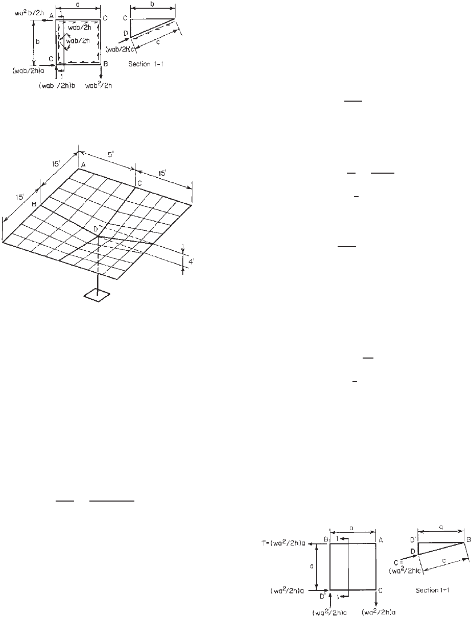
It can be seen that if the load is applied uniformly
over the horizontal projection of the surface, compres-
sive membrane stress results in the concave downward
parabolas, and tensile membrane stress results in the
concave upward parabolas. These tensile and compressive
membrane stresses are uniform throughout the surface and
are equal to wab/2h, in which w is the applied load per
unit surface area (Fig. 9.35). Since the compressive and
tensile membrane stresses are equal in magnitude and are
perpendicular to each other, a state of pure shear occurs in
planes of 45
◦
from the direction of either membrane stress.
Thus only shear stress need be transmitted along the joints
of the panels. The force in edge beams resulting from the
shear of q = wab/2h along the edge members is shown in
Fig. 9.35.
338 9 SHEAR DIAPHRAGMS AND ROOF STRUCTURES
Figure 9.35 Membrane and shear stresses in panels and forces
in framing members.
Figure 9.36 Example 9.4.
Example 9.4 illustrates the design of an inverted hyper-
bolic umbrella by using the membrane theory.
Example 9.4 Use the ASD method to design the inverted
steel hyperbolic paraboloid umbrella roof shown in
Fig. 9.36
9.76
for w = 30 psf on horizontal projection. Use
A36 steel for framing members.
SOLUTION
1. Determination of Panel Shear. The panel shear can be
determined as follows:
v =
wa
2
2h
=
30 × (15)
2
2 × 4
= 845 lb/ft
In accordance with Section D5 of the AISI specifi-
cation (Table 9.1), the factor of safety for gravity load
alone is 2.45 for welded connections. The required
ultimate shear strength of the roof deck system is
therefore
v
u
= 845(2.45) = 2070 lb/ft
2. Selection of Steel Roof Deck. Select a type of steel roof
deck from catalogs to satisfy the following require-
ments:
a. Flexural strength
b. Shear strength
c. Deflection
3. Design of Framing Members
a. Tension Members AB and AC. Considering the
quadrant ABCD as shown in Fig. 9.34, the tensile
force is
T = va =
wa
2
2h
a = 845(15) = 12, 680 lb
Using the AISC ASD specification with an
allowable stress of 22 ksi for A36 steel, the
required area is
A =
T
F
=
12.68
22
= 0.58 in.
2
Using L4 × 3 ×
1
4
in., the actual area is 1.69 in.
2
b. Compression Members BD and CD. Considering
section 1–1 of Fig. 9.37, the compressive force is
C = vc =
wa
2
2h
c = 845(15.55) = 13, 140 lb
Since the compression member will support two
quadrants, the total compressive force for design is
C
= 2C = 2(13,140) = 26,280 lb
Using the AISC ASD Specification with an
allowable stress of 22 ksi, the required area is
A =
C
22
= 1.195 in.
2
Selecting two L4 × 3 ×
1
4
in., the actual area is 3.38 in.
2
The use of an allowable stress of 22 ksi is due to the fact
that the compressive force varies from zero at point B to
the maximum value at point D and that the member is
continuously braced by steel panels.
The above discussion is based on the requirement
of strength. In some cases the deflection of hyperbolic
paraboloid roofs at unsupported corners may be excessive
and therefore will control the design of this type of
structure. Research work
9.80
indicates that the corner
Figure 9.37 Forces in framing members.
SHELL ROOF STRUCTURES 339
deflection is affected by (1) the shear and bending stiffness
of steel panels, (2) the bending and axial stiffness of edge
members, (3) the type and arrangement of connections
used to join steel panels and to connect steel panels
to edge members, and (4) the eccentricity of the shear
force transmitted from the deck to edge members. The
finite-element method may be used to predict deflection.
If the corner deflection is found to be critical, the design
may be improved by increasing the bending stiffness of the
edge members and steel panels and the curvature of the
shell.
In the design of hyperbolic paraboloid roofs, considera-
tion should also be given to the possible buckling of the
steel deck and the overall buckling of edge members. The
determination of the buckling load can be made by either
the energy approach or the finite-element method.
9.80
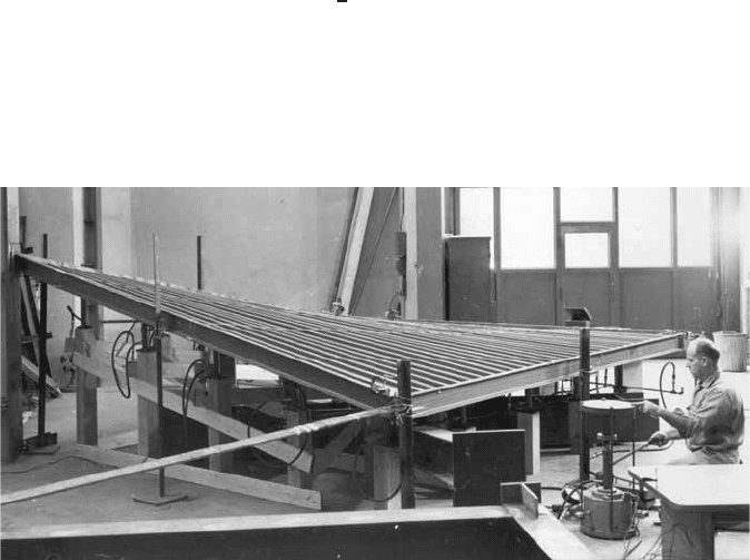
9.4.3.4 Research on Cold-Formed Steel Hyperbolic
Paraboloid Roofs A full-scale hyperbolic paraboloid
shell constructed of one-layer standard steel roof deck
sections has been tested at Cornell University by Nilson.
9.79
The test setup is shown in Fig. 9.38. Note that the jack
loads are applied upward because of convenience of
testing. The specimen was 15 × 15 ft (4.6 × 4.6 m) with a
3-ft (0.92-m) rise, which represents one of the four quarter
surfaces of an inverted umbrella (type II), as shown in
Fig. 9.30. The panels used in the specimen were standard
0.0635-in.- (1.6-mm-) thick steel roof deck sections, 18 in.
(457 mm) wide, with ribs 6 in. (152 mm) on centers and 1
1
2
in. (38 mm) high. Panels were welded to each other along
the seam joints and to the perimeter frame members.
The structural feasibility of the hyperbolic paraboloid
shell structure has been demonstrated by Nilson’s test. The
results indicate that shear values obtained from horizontal
diaphragm testing can be used conservatively in the design
of curved shear surfaces.
The structural behavior of a hyperbolic paraboloid shell
has been studied further at Cornell University by Winter,
Gergely, Muskat, Parker, and Banavalkar under the spon-
sorship of the AISI. Findings of this study are reported
in Refs. 9.80 and 9.82–9.87. In addition, investigations of
hyperbolic paraboloid roofs have been conducted by indi-
vidual steel companies.
9.88
It is expected that additional
design information may be developed from the previous
research.
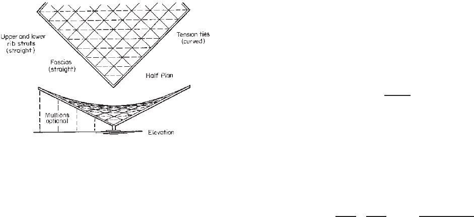
9.4.3.5 Curvilinear Grid Frame-Type Hyperbolic Para-
boloids
9.72,9.75
The above discussion is made on the basis
that the cold-formed panels are stressed as a membrane
in the hyperbolic paraboloid roof. This membrane type of
hyperbolic paraboloid structure is mostly used for rela-
tively small structures. For larger structures a hyperbolic
paraboloid roof may be constructed with structural members
as a curvilinear grid frame. The construction shown in Fig.
9.39 was developed by Hutton of Purdue University and
consists of struts and ties. The ties of the system can be
designed as cables. Either analytical or graphic solutions
are possible.
With regard to the design of ribs, the top ribs are designed
for compression and bending and the bottom ribs are
designed for compression only. The fascia is designed for
combined axial and bending stress. In addition, the ground
tie should be provided as a tension member.
In the curvilinear grid frame type, cold-formed steel
decks do not participate in shear membrane stresses; rather
a grid of structural steel members supports the loads.
Two grid frame methods are possible. They are the
double-arch and the orthogonal systems. For the double-
arch grid system, the positive arches are compressive
Figure 9.38 Testing of hyperbolic paraboloid shell.
9.79
340 9 SHEAR DIAPHRAGMS AND ROOF STRUCTURES
Figure 9.39 Curvilinear grid frame type hyperbolic para-
boloid.
9.76
elements and the negative arches are curved tensile
members. The analysis of this system for concentrated
load and unbalanced load can be complex.
For the orthogonal grid system, as shown in Fig. 9.39,
the ribs are straight members parallel to the edge members
and supported by a series of ties. Two layers of corrugated
steel panels may be used perpendicular to each other to
replace the ribs.
In addition to the types of shell roofs discussed above,
two structural systems (barrel shells and composite truss
and sheet panels) generally used for lightweight utility and
farm buildings have been discussed by Abdel-Sayed in
Ref. 9.89.
9.5 METAL ROOF SYSTEMS
For metal roof systems framed using cold-formed steel
C- or Z-section purlins the attached metal roof panel may
influence the structural performance of the C- or Z-section.
Sections 4.24 and 4.25 summarize the behavior of beams
having one flange attached to deck or sheathing. Section
5.7 provides the AISI design provisions for a compression
member having one flange attached to deck or sheathing.
Because the C- or Z-section is singly or point symmetric,
the application of gravity loads will cause torsion in the
purlin and lateral displacements of the roof system. This
behavior is due to the slope of the roof, the loading
of the member eccentric to its shear center, and for the
Z-section the inclination of the principal axes. The lateral
displacements may create instability of the roof system.
The capacity of the purlin roof system is dependent upon
the abilty of the roof system to restrain the purlins and
therefore minimize the torsion in the sections. To avoid
an instability of the roof system, lateral stability may be
provided by the roof sheathing and anchorage devices. The
anchorage device is designed to resist the lateral anchorage
force that is generated in the roof system
9.117–9.120
.
Research by Neubert and Murray
9.121
determined that
the anchorage force P
Lj
can be determined by calculating
the force introduced into the system by each purlin and
then multiplying by a reduction factor that accounts for
the system stiffness. Equation (9.75) defines the anchorage
force to be resisted by each anchorage device,
P
L
j
=
N
p
i=1
P
i
K
effi,j
K
total
i
(9.75)
where P
i
is the anchorage force introduced into the system
by each purlin and the reduction factor is the ratio of the
effective stiffness of the anchorage device, K
eff
to the total
stiffness of all system elements providing support to the
purlin, K
total
.
The anchorage force for each purlin anchored to a rigid
anchor is
P
i
= (C
1
)W
p
i
C
2
1000
I
xy
L
I
x
d
+ (C
3
)
(m + 0.25b)t
d
2
× α cos θ −(C
4
) sin θ
(9.76)
where C
1
,C
2
,C
3
,C
4
= support restraint coefficients
W
pi
= total required vertical load
supported by the i
th
purlin in a
single bay
I
xy
= product of inertia of full
unreduced section about
centroidal axes parallel and
perpendicular to the purlin web
(I
xy
= 0 for C-sections)
L = purlin span length
m = distance from shear center to
midplane of web (m = 0for
Z-sections)
b = top flange width of purlin
t = purlin thickness
I
x
= moment of inertia of full
unreduced section about
centroidal axis perpendicular to
purlin web
d = depth of purlin
α =+1 for top flange facing in
up-slope direction
= -1 for top flange facing in
down-slope direction
θ = angle between vertical and plane
of purlin web
The stability of each purlin is provided by the total
effective stiffness of all elements providing support to the
purlin. This total effective stiffness is a combination of

METAL ROOF SYSTEMS 341
inherent system stiffness and the effective stiffness of each
anchorage device as defined by
K
total,i
=
N
a
j=1
K
eff
i,j
+ K
sys
(9.77)
The inherent stiffness K
sys
isameasureoftheresis-
tance to lateral displacement of the purlin. This resistance is
from the fixity of the purlin to the rafter connection and the
moment resistance at the panel-to-purlin interface connec-
tion. The inherent stiffness is
K
sys
=
C
5
1000
(N
p
)
ELt
2
d
2
(9.78)
Where C
5
reflects the stiffness of the rotational spring
constant for the connections.
The stiffness K
eff
is the effective anchor stiffness which
consists of the anchor device stiffness and the axial behavior
of the roof panel acting in series,
K
eff
=
1
K
a
+
d
p
i,j
(C6)LA
p
E
−1
(9.79)
where K
a
is the lateral stiffness of the anchorage device, A
p
is the cross-sectional area of the roof panel per unit width,
and C
6
relates the cross-sectional area and the purlin span.
The previous discussion focused on the required strength
for an anchorage device; however, for an anchorage device
to function properly in a roof system it must provide a
minimum level of stiffness as defined by
K
req
=
20
N
p
i=1
P
i
d
(9.80)
Additional background information as well as design
examples are given in Ref. 9.122.
CHAPTER 10
Corrugated Sheets
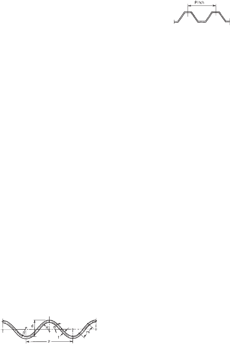
10.1 GENERAL REMARKS
Corrugated sheets (Fig. 10.1) have been used in building
construction since about 1784. This is one of the oldest
types of cold-formed steel products. At present, numerous
types of corrugated sheets with different coatings are being
produced by many manufacturers. Several standard corru-
gated steel sheets are generally available for building
construction and other usage.
In general, the design methods described in previous
chapters are also applicable to the design and use of corru-
gated steel sheets. However, certain simplified formulas for
computing the sectional properties of standard corrugated
steel sheets can be used in design. Following an investiga-
tion conducted by the AISI during 1955–1957, a publication
entitled “Sectional Properties of Corrugated Steel Sheets”
was issued by the Institute in 1964 to provide the necessary
design information for corrugated sheets.
1.87
This chapter is intended to discuss the a pplication
of arc-and-tangent-type corrugated steel sheets and
trapezoidal-type corrugated sheets (Fig. 10.2) and the
design of such cold-formed steel products. The information
included herein is based on AISI publications
1.87–1.89
and
other references.
Figure 10.1 Cross section of typical arc- and tangent-type corru-
gated sheets.
Figure 10.2 Cross section of typical trapezoidal-type corrugated
sheets.
10.2 APPLICATIONS
Corrugated steel sheets are frequently used for roofing
and siding in buildings because the sheets a re strong,
lightweight, and easy to erect. In many cases, they are used
as shear diaphragms to replace conventional bracing and
to stabilize entire structures or individual members such
as columns and beams.
10.19,10.20
The shear diaphragms and
diaphragm-braced beams a nd columns were discussed in
Chapter 9.
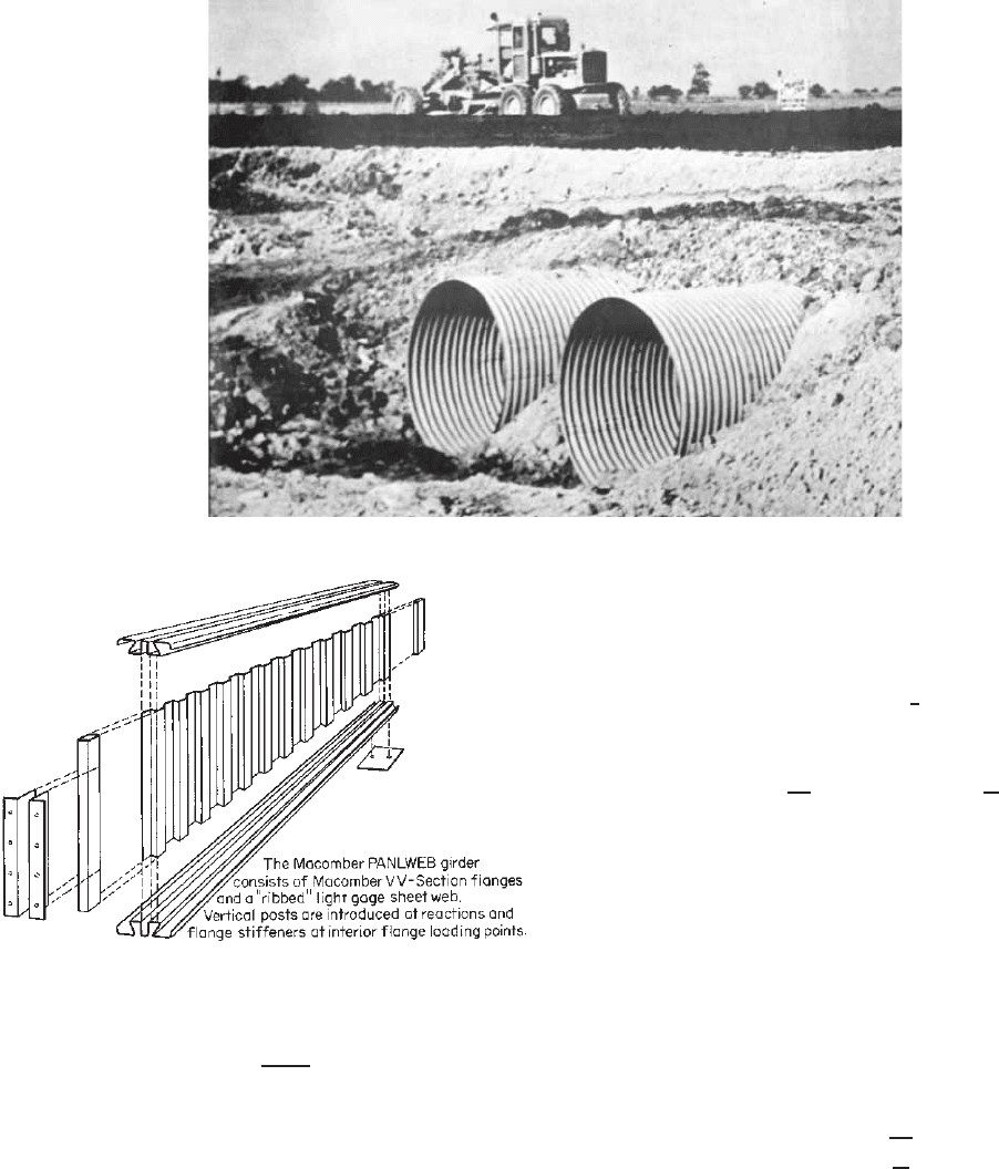
Figure 1.18a shows the use of standard corrugated
sheets for exterior curtain wall panels. The application of
unusually large corrugated sections in frameless stressed-
skin construction is shown in Fig. 1.18b. In addition,
corrugated steel pipe of galvanized sheets has long been
used in drainage structures for railways, highways, and
airports.
1.18,1.88,1.89
Figure 10.3 shows a typical corrugated
metal pipe culvert used for highway systems. Other corru-
gated steel products have been used for retaining walls,
guardrails, conveyor covers, aerial conduits, and other
purposes.
1.18,1.88
During recent years, corrugated sheets have been
used in flooring systems for buildings and bridge
construction.
1.88,10.1
These products have also been used
as web elements for built-up girders in order to increase
web stiffness instead of using a relatively thicker plate or
a thin web with stiffeners. The Macomber Panlweb girder
shown in Fig. 10.4 consists of 0.075–0.15 in. (1.9–3.8
mm) corrugated web for depths of 20–40 in. (0.51–1.02
m).
10.2
Reference 10.3 discusses the required connections
for beams with corrugated webs. The fatigue strengths of
girders with corrugated webs were reported in Refs. 10.4
and 10.25.
10.3 SECTIONAL PROPERTIES AND DESIGN
OF ARC- AND TANGENT- TYPE CORRUGATED
SHEETS
In 1934, Blodgett developed a method to compute the
sectional properties of arc- and tangent-type corrugated
sheets.
10.5
The computation of the moment of inertia and
the section modulus for standard corrugated sheets has been
simplified by Wolford.
10.6
In the computation, design curves
and tables can be used to determine factors C
5
and C
6
in
Eqs. 10.1 a nd 10.2
1.87
:
I = C
5
bt
3
+ C
6
bd
2
t (10.1)
343
344 10 CORRUGATED SHEETS
Figure 10.3 Typical corrugated metal pipe culvert installatio n on interstate highway system.
1.87
Figure 10.4 Macomber Panlweb girder.
10.2
S =
2I
d + t
(10.2)
where I = moment of inertia, in.
4
S = section modulus, in.
3
b = width of sheet, in.
d = depth of corrugation, in.
t = thickness of sheet, in.
C
5
,C
6
= factors depending on shape of
arc-and-tangent-type corrugation.
Using Wolford’s charts, as s hown in Figs. 10.5–10.9,
the values of the moment of inertia, section modulus, area,
radius of gyration, and length of tangent can be computed
by the following procedure:
1. Compute the midthickness radius R
,
R
= R +
1
2
t
2. Compute values of q and K,
q =
R
d
and K =
p
d
where p is the pitch.
3. From Fig. 10.5, determine the angle α for the
computed values of q and K .
4. From Figs. 10.6 and 10.7, determine C
5
and C
6
by
using K and angle α.
5. From Figs. 10.8 and 10.9, determine λ and the m/d
ratio.
6. Compute I and S by using Eqs. 10.1 and 10.2.
7. Compute
A = λbt
8. The radius of gyration is
r =
I
A
9. The length of the tangent is d × m/d.
Based on the method outlined above, the sectional prop-
erties of several types of corrugated sheets have been devel-
oped and published in Refs. 1.87 and 1.88. The accuracy
of Eqs. (10.1) and (10.2) has been verified by beam tests
conducted under the sponsorship of the AISI. Some of the