Yu W., LaBoube R.A. Cold-Formed Steel Design
Подождите немного. Документ загружается.

STEEL SHEAR DIAPHRAGMS 315
1
Length, a
L
v
L
v
L
v
C
Beam
L
Bearing
reaction
C
D
Tension
reaction
Steel deck
panel
Load, P
A
B
Depth, b
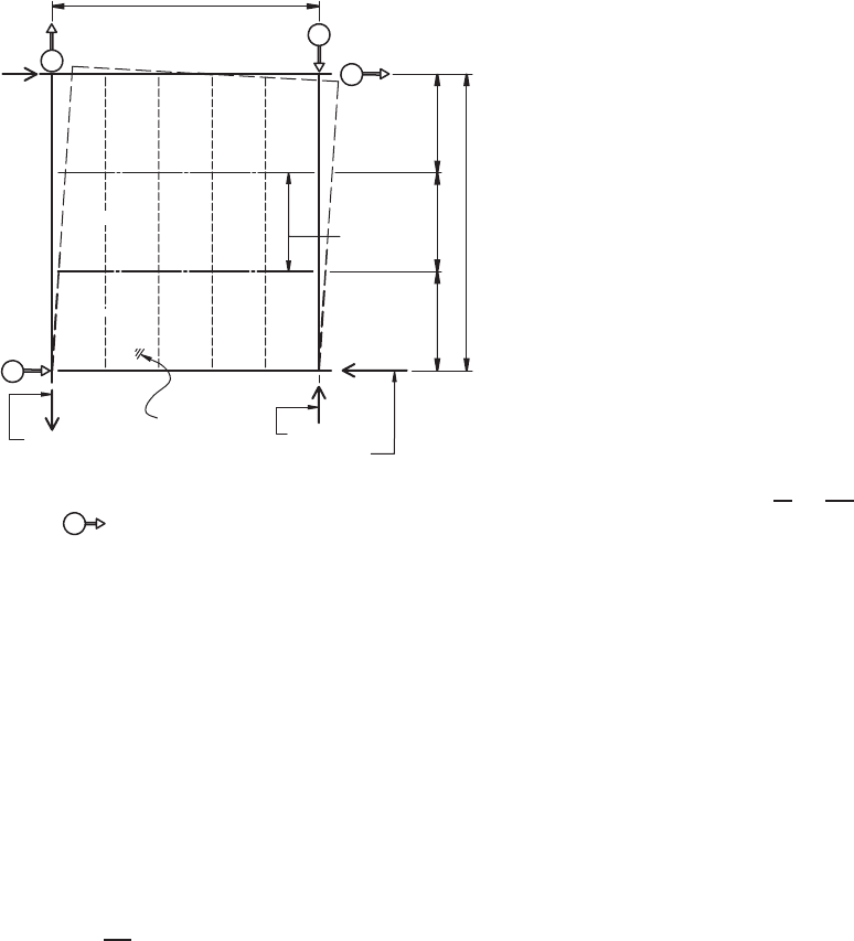
Legend:
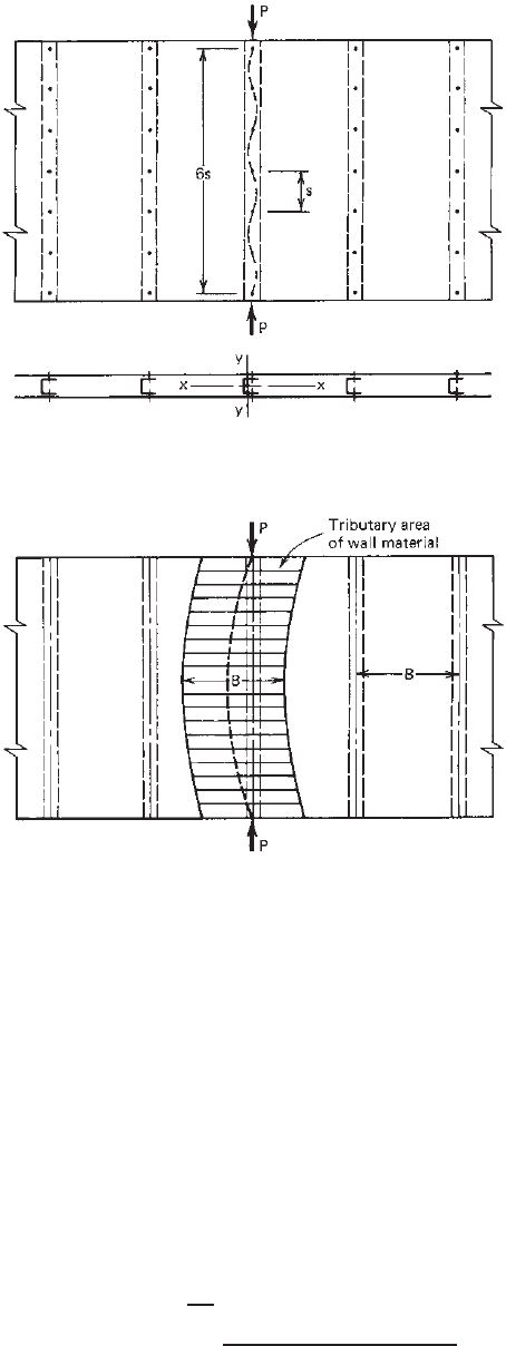
Displacement device mounted on the ground at frame
corners measuring movement of the test frame.
Arrow indicates direction of positive readin
g
.
3
2
4
Figure 9.9 Rectangular displacement measurements.
9.114
on vertical loads. The diaphragm system, including connec-
tion details, needed to resist horizontal loads can then be
designed on the basis of (1) the shear strength and the stiff-
ness of the panels recommended by individual companies
for the specific products and (2) the design provisions of
local building codes.
For the design of shear diaphragms according to Section
D5 of the AISI North American specification,
1.345
the
design shear strength can be determined as follows:
S
d
=
⎧
⎨
⎩
S
n
d
for ASD method (9.14a)
S
d
= φ
d
S
n
for LRFD method (9.14b)
where S
d
= design shear strength for diaphragm, lb/ft.
S
n
= in-plane diaphragm nominal shear strength
established by calculation or test, lb/ft
d
= safety factor for diaphragm shear as specified
in Table 9.1
φ
d
= resistance factor for diaphragm shear as
specified in Table 9.1
In Table 9.1, the safety factors and resistance factors
are based on the statistical studies of the nominal and
mean resistances from full-scale tests.
1.346
The values in
Table 9.1 reflect the fact that the quality of mechanical
connectors is easier to control than welded connections.
As a result, the variation in the strength of mechanical
connectors is smaller than that for welded connections, and
their performance is more predictable. Therefore, a smaller
factor of safety, or larger resistance factor, is justified for
mechanical connections.
1.346
For mechanical fasteners other than screws
d
shall not
be less than Table 9.1 values for screws and φ
d
shall not
be greater than Table 9.1 values for screws.
The safety factors for earthquake loading are slightly
larger than those for wind load due to the ductility demands
required by seismic loading.
The stress in the perimeter framing members should
be checked for the combined axial stresses due to the
gravity load and the wind load or earthquake applied to
the structure.
As shown in Fig. 9.10, the axial stress in the perimeter
framing members due to horizontal load (wind load or
earthquake) can be determined by
f =
F
A
=
M
Ab
(9.15)
where f = stress in tension or compression, psi
F = force in tension or compression, lb, = M/b
M = bending moment at particular point
investigated, ft-lb
A = area of perimeter framing member, in.
2
b = distance between centroids of perimeter
members, measured perpendicular to span
length of girder, ft
Usually the shear stress in panels and the axial stress
in perimeter members of such a diaphragm assembly are
small, and it is often found that the framing members and
panels which have been correctly designed for gravity loads
will function satisfactorily in diaphragm action with no
increase in size. However, special attention may be required
at connections of perimeter framing members. Ordinary
connections may deform in the crimping mode if subjected
to heavy axial forces along connected members.
If the panels are supported by a masonry wall rather than
by a steel frame, tensile and compressive reinforcements
should be provided for flange action within the walls
adjacent to the diaphragm connected thereto.
In addition to designing shear diaphragm and perimeter
members for their strengths, the deflection of shear
diaphragms must also be considered. The total deflection
of shear diaphragms may be computed as
total
=
b
+
s
(9.16)
where
total
= total deflections of shear diaphragm, in.
b
= bending deflection, in.
316 9 SHEAR DIAPHRAGMS AND ROOF STRUCTURES
Table 9.1 Safety Factors and Resistance Factors for Diaphragms
1.345
Load Limit State
Type or
Connection Related Panel Buckling
a
Combinations Connection
d
φd
d
φd
Including Type
ASD LRFD LSD ASD LRFD LSD
Earthquake Welds 3.00 0.55 0.50
Screws 2.50 0.65 0.60
Wind Welds
2.35 0.70 0.65 2.00 0.80 0.75
Screws
All others Welds 2.65 0.60 0.55
Screws 2.50 0.65 0.60
a
Panel buckling is out-of-plane buckling and not local buckling at fasteners.
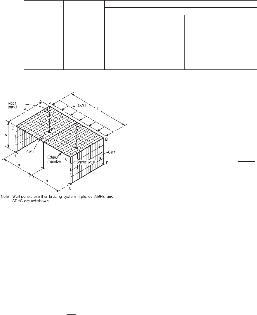
Figure 9.10 Portal frame building with wall and roof
diaphragm.
9.42
s
= shear deflection, including deflection due
to seam slip and local distortion, in.
The bending deflection and shear deflection can be
computed by the formulas given in Table 9.2 for various
types of beams subjected to various loading conditions.
In Table 9.2 the formula for determining the shear deflec-
tion of a diaphragm is similar to the method of computing
the shear deflection of a beam having relatively great depth.
It can be derived from the following equation
4.45
:
s
=
Vv
G
b
dx (9.17)
where V = shear due to actual loads
v = shear due to a load of 1 lb acting at section
where deflection is derived
G
= shear stiffness of diaphragm
b = width of shear diaphragm or depth of
analogous beam
In practical design, the total horizontal deflection of
a shear diaphragm must be within the allowable limits
permitted by the applicable building code or other design
provisions. The following formula for masonry walls has
been proposed by the Structural Engineers Association of
California:
Allowable deflection =
h
2
f
0.01Et
(9.18)
where h = unsupported height of wall, ft
t = thickness of wall, in.
E = modulus of elasticity of wall material, psi
f = allowable compressive stress of wall
material, psi
9.2.6 Special Considerations
The following are several considerations which are essential
in the use of steel panels as shear diaphragms.
1. If purlins and girts are framed over the top of
perimeter beams, trusses, or columns, the shear plane of
the panels may cause tipping of purlin and girt members
by eccentric loading. For this case, rake channels or other
members should be provided to transmit the shear from the
plane of the panels to the flanges of the framing member
or to the chords of the truss.
2. Consideration should be given to the interruption
of panels by openings or nonstructural panels. It may
be assumed that the effective depth of the diaphragm is
equal to the total depth less the sum of the dimensions
of all openings or nonstructural panels measured parallel
to the depth of the diaphragm. The type of panel-to-frame
fasteners used around the openings should be the same as,
and their spacing equal to or less than, that used in the tests
to establish the diaphragm value.
STEEL SHEAR DIAPHRAGMS 317
Table 9.2 Deflection of Shear Diaphragms
9.42
Type of Diaphragm Loading Condition
b
s
a
Simple beam (at center) Uniform load
5wL
4
(12)
2
384EI
wL
2
8G
b
Load P applied at center
PL
3
(12)
3
48EI
PL
4G
b
Load P applied at each
1
3
point of span
23PL
3
(12)
3
648EI
PL
3G
b
Cantilever beam (at free end) Uniform load
wa
4
(12)
3
8EI
wa
2
2G
b
Load P applied at free end
Pa
3
(12)
3
3EI
Pa
G
b
a
When the diaphragm is constructed with two or more panels of different lengths, the term G
b should be replaced by
G
i
b
i
,where
G
i
and b
i
are the shear stiffness and the length of a specific panel, respectively.
3. When panels are designed as shear diaphragms, a note
shall be made on the drawings to the effect that the panels
function as braces for the building and any removal of the
panels is prohibited unless other special separate bracing is
provided.
4. The performance of shear diaphragms depends
strongly on the type, spacing, strength, and integrity of the
fasteners. The type of fasteners used in the building should
be the same as, and their spacing not larger than, that used
in the test to establish the diaphragm value.
5. Diaphragms are not effective until all components are
in place and fully interconnected. Temporary shoring should
therefore be provided to hold the diaphragms in the desired
alignment until all panels are placed, or other construction
techniques should be used to make the resulting diaphragm
effective. Temporary bracing should be introduced when
replacing panels.
6. Methods of erection and maintenance used for the
construction of shear diaphragms should be evaluated care-
fully to ensure proper diaphragm action. Proper inspection
and quality control procedures would be established to
ensure the soundness and spacing of the connections.
For other guidelines on practical considerations, erection,
inspection, and other design information, see Refs. 9.45 and
9.111.
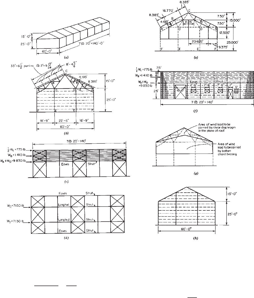
Example 9.1 Use the ASD method to design a longitu-
dinal bracing system by using steel shear diaphragms for
a mill building as shown in Figs. 9.11a and b. Assume
thatawindloadof20psfisappliedtotheendwallofthe
building and that corrugated steel sheets having a base metal
thickness of 0.0198 in. are used as roof and wall panels.
SOLUTION
A. Alternate I . Longitudinal X-bracing is usually provided
for a mill building in the planes of the roof, side walls,
and lower chord of the truss,
∗
as shown in Figs. 9.8c and
d. The intent of this example is to illustrate the use of
shear diaphragms in the planes of the roof and side walls
instead of the X-bracing system. The design of the roof
truss and other structural members is beyond the scope of
this example.
1. Wind Panel Loads. The wind panel loads at A, B, C, and
D can be computed as follows based on the assumed
area in Fig. 9.11e:
W
A
= 20(9.375 ×12.5 +
1
2
× 8.385 × 4.193)
= 2700 lb
W
B
= 20(16.77 ×4.193) = 1410 lb
W
C
= 20(8.385 ×4.193 +
1
2
× 11.25 × 7.5)
= 1550 lb
W
D
= 20(20.635 ×12.5 + 5.625 × 7.5 +
1
2
× 7.5
× 15.0) = 7130 lb
2. Shear Diaphragm in Plane of Roof. Considering that the
planes of the side walls and the lower chord of the truss
are adequately braced, the wind loads to be resisted by
the roof panels used as a shear diaphragm are
1
2
W
C
and
W
B
as indicated in Fig. 9.11f . Consequently, the shear
developed along the eave struts is
∗
See Alternate II, in which the X-bracing is eliminated in the plane of the
lower chord of the truss.
318 9 SHEAR DIAPHRAGMS AND ROOF STRUCTURES
Figure 9.11 (a) Mill building. (b) End elevation. (c) Wind bracing in planes of roof and side
walls, side elevation. (d ) Bracing in plane of lower chord. (e)Assumedareaofwindloadtobe
carried at A, B, C, and D.(f ) Shear diaphragms in planes of roof and side walls, side elevation.
(g) Assumed area of wind load to be carried in planes of roof and bottom chord of truss. (h)End
wall columns run all the way to roof plane.
v =
775 + 1410
140
=
2185
140
= 15.6lb/ft
From Table A.1 of Appendix A of Ref. 9.42, the
average nominal shear strength for the corrugated sheets
having a base metal thickness of 0.0198 in. is 370 lb/ft.
Using a safety factor of 2.35 as recommended by AISI
for screw connectors, the allowable shear strength for
the design is
S
des
=
370
2.35
= 157 lb/ft
Since the allowable shear is much larger than the
actual shear value of 15.6 lb/ft developed in the roof

STRUCTURAL MEMBERS BRACED BY DIAPHRAGMS 319
due to the wind load, the roof panels are adequate
to resist the wind load applied to the end wall, even
though no intermediate fasteners are provided. Usually
intermediate fasteners are used for roof panels, and as
a result, additional strength will be provided by such
fasteners.
3. Shear Diaphragm in Plane of Side Wall. As far as the
shear diaphragms in the planes of the side walls are
concerned, the total load to be resisted by one side wall
asshowninFig.9.11f is
P = W
A
+ W
B
+
1
2
W
C
+ W
D
= 2700 +1410 + 775 + 7130 = 12,015 lb
The effective diaphragm width b
eff
is the length of
the building with the widths of doors and windows
subtracted. This is based on the consideration that the
wall panels are adequately fastened to the perimeter
members around openings, that is,
b
eff
= 140 −(16.0 + 3 × 7.5 +7.0 + 5.0) = 89.5ft
Therefore the shear to be resisted by the diaphragm
is
v =
P
b
eff
=
12, 015
89.5
= 134 lb/ft
or the required static ultimate shear resistance should be
S
u
= S
d
× SF = 134 × 2.35 = 315 lb/ft
Since the average nominal shear strength for the
0.0198-in.-thick corrugated sheets spanning at 3 ft is
370 lb/ft, which is larger than the computed value of
315 lb/ft, the corrugated sheets are adequate for shear
diaphragm action.
In determining the wind load to be resisted in the
planes of roof and side walls, assumptions may be made
asshowninFig.9.11g. Based on this figure, the wind
load to be resisted by the shear diaphragm in the plane of
the roof is 2250 lb, which is slightly larger than the load
of 2185 lb used previously. The total load to be used for
the design of the shear diaphragm in the planes of side
walls is the same as the load computed from Fig. 9.11f .
4. Purlin Members. It should be noted that the shear force
in the plane of roof panels can cause the tipping of
purlins due to eccentricity. Rake channels or other means
may be required to transmit the shear force from the
plane of roof panels to chord members. This can become
important in short, wide buildings if purlins are framed
over the top of trusses.
B. Alternate II. When end-wall columns run all the way to
the roof plane, as shown in Fig. 9.8h, there is no need for
X-bracing in the plane of the bottom chord. For this case,
the force to be resisted by one side of the roof diaphragm
is
P = 20 ×
1
2
[(12.5 + 20) × 30] = 9750 lb
and
v =
9750
140
= 69.7lb/ft.
The above shear developed along the eave struts is
smaller than the allowable shear of 180 lb/ft for 0.0198-
in.-thick corrugated sheets. Therefore, the roof panels are
adequate to act as a diaphragm.
For side walls, the shear to be resisted by the diaphragm
is
v =
P
b
eff
=
9750
89.5
= 109 lb/ft
or the required static ultimate shear resistance is
S
u
= 109 ×2.35 = 256 lb/ft
Since the above computed S
u
is less than the nominal
shear strength of 370 lb/ft for the 0.0198-in.-thick sheets,
the wall panels are also adequate to act as a shear
diaphragm. The X-bracing in the plane of the side walls
can therefore be eliminated.
9.3 STRUCTURAL MEMBERS BRACED BY
DIAPHRAGMS
9.3.1 Beams and Columns Braced by Steel
Diaphragms
In Section 9.2 the application of steel diaphragms in
building construction was discussed. It has been pointed
out that in addition to utilizing their bending strength and
diaphragm action the steel panels and decking used in walls,
roofs, and floors can be very effective in bracing members
of steel framing against overall buckling of columns and
lateral buckling of beams in the plane of panels. Both theo-
retical and experimental results indicate that the failure load
of diaphragm-braced members can be much higher than
the critical load for the same member without diaphragm
bracing.
In the past, investigations of thin-walled steel open
sections with and without bracing have been conducted
by numerous investigators. Since 1961 the structural
behavior of diaphragm-braced columns and beams has
been studied at Cornell by Winter, Fisher, Pincus, Errera,
Apparao, Celebi, Pekoz, Simaan, Soroushian, Zhang,
and others.
4.115–4.118,4.123,4.125–4.128,4.133,4.136,9.50–9.57
In
these studies, the equilibrium and energy methods have
been used for diaphragm-braced beams and columns. In
addition to the Cornell work, numerous studies have been
conducted at other institutions and several individual steel
companies.
4.119–4.122,4.124,4.129–4.132,4.134,4.135,9.58–9.66
320 9 SHEAR DIAPHRAGMS AND ROOF STRUCTURES
9.3.2 Diaphragm-Braced Wall Studs
In Section 5.10 the application of wall studs in building
construction was briefly discussed. Because the shear
diaphragm action of wall material can increase the load-
carrying capacity of wall studs significantly, the effect of
sheathing material on the design load of wall studs was
previously considered in Sections D4(b) and D4.1–D4.3 of
the AISI Specification.
1.314
However, it should be noted
that the AISI design requirements are now given in the
Wall Stud Standard
13.4
(AISI S211-07) and are limited only
to those studs that have identical wall material attached to
both flanges. When unidentical wall materials are attached
to two flanges, the reader is referred to Refs. 9.52–9.55 or
the rational design method of AISI S211 may be used based
on the weaker wall material.
Prior to the 2004 Supplement to the AISI
Specification
1.343
consideration was given to the structural
strength and stiffness of the wall assembly. As far as the
structural strength is concerned, the maximum load that
can be carried by wall studs is governed by either (1)
column buckling of studs between fasteners in the plane
of the wall (Fig. 9.12) or (2) overall column buckling of
studs (Fig. 9.13). The following discussion deals with the
critical loads for these types of buckling. A discussion
of the current AISI Wall Stud Standard’s rational design
method is presented in Section 13.2.2.4.
9.3.2.1 Column Buckling of Wall Studs between
Fasteners When the stud buckles between fasteners, as
shown in Fig. 9.12, the failure mode may be (1) flexural
buckling, (2) torsional buckling, or (3) torsional–flexural
buckling, depending on the geometric configuration of the
cross section and the spacing of fasteners. For these types
of column buckling, the critical loads are based on the
stud itself, without any interaction with the wall material.
Therefore the design formulas given in Sections 5.3 and
5.4 are equally applicable to these cases.
9.3.2.2 Overall Column Buckling of Wall Studs Braced
by Shear Diaphragms on Both Flanges The overall
column buckling of wall studs braced by sheathing mate-
rial has been studied extensively at Cornell University and
other institutions. The earlier AISI provisions were devel-
oped primarily on the basis of the Cornell work.
9.52–9.55
Even though the original research has considered the shear
rigidity and the rotational restraint of the wall material that
is attached either on one flange or on both flanges of the
wall studs, for the purpose of simplicity, the AISI design
requirements are provided only for the studs braced by
shear diaphragms on both flanges. In addition, the rota-
tional restraint provided by the wall material is neglected
in the AISI provisions.
Figure 9.12 Buckling of studs between fully effective fasteners.
Figure 9.13 Overall column buckling of studs.
Based on their comprehensive studies of wall assemblies,
Simaan and Pekoz have shown several stability equations
for determining the critical loads for different types of
overall column buckling of wall studs.
9.55
The following
buckling load equations are used for channels or C-sections,
Z-sections, and I-sections having wall materials on both
flanges:
1. Singly Symmetric Channels or C-sections
a. for flexural buckling about y axis
P
cr
= P
y
+
¯
Q (9.19)
b. for torsional–flexural buckling
P
cr
=
1
2β
[(P
x
+ P
zQ
) (9.20)
−
(P
x
+ P
zQ
)
2
− 4βP
x
P
zQ
]
STRUCTURAL MEMBERS BRACED BY DIAPHRAGMS 321
where P
cr
is the critical buckling load in kips, the
euler flexural buckling load about the x axis of wall
studs in kips is
P
x
=
π
2
EI
x
(K
x
L
x
)
2
(9.21)
the Euler flexural buckling load about the y axis
of wall studs in kips is
P
y
=
π
2
EI
y
(K
y
L
y
)
2
(9.22)
the torsional buckling load about the z axis of wall
studs in kips is
P
z
=
π
2
EC
w
(K
t
L
t
)
2
+ GJ
1
r
2
0
(9.23)
and
P
zQ
= P
z
+
¯
Qd
2
4r
2
0
(9.24)
where
¯
Q = shear rigidity for two wallboards,
kips
d = depth of channel or C-section, in.
Other symbols are as defined in Sections 5.4
and 5.7.
2. Z-Sections
a. for torsional buckling about z axis
P
cr
= P
zQ
= P
z
+
¯
Qd
2
4r
2
0
(9.25)
b. for combined flexural buckling about x and y
axes
P
cr
=
1
2
P
x
+ P
y
+
¯
Q
(9.26)
−
(P
x
+ P
y
+
¯
Q)
2
− 4(P
x
P
y
+ P
x
¯
Q − P
2
xy
)
where
P
xy
=
π
2
EI
xy
(K
x
K
y
L
2
)
(9.27)
and I
xy
is the product of the inertia of wall studs,
in.
4
3. Doubly Symmetric I-Sections
a. for flexural buckling about y axis
P
cr
= P
y
+
¯
Q (9.28)
b. for flexural buckling about x axis
P
cr
= P
x
(9.29)
c. for torsional buckling about z axis
P
cr
= P
zQ
= P
z
+
¯
Qd
2
4r
2
0
(9.30)
By using the above equations for critical loads,
the critical elastic buckling stress σ
cr
can be
computed as
σ
cr
=
P
cr
A
(9.31)
9.3.2.3 AISI Design Criteria for Wall Studs The AISI
North American Specification
1.345
permits sheathing braced
design in accordance with an appropriate theory, tests, or
rational engineering analysis. The following excerpts are
adapted from Section D4 of the 1996 edition of the AISI
specification for the design of wall studs.
1.314
These excepts
may be considered an appropriate theory for design. A
discussion of the current AISI North American Standard
for Cold-Formed Steel Framing—Wall Stud Design rational
method is presented in Section 13.2.2.4.
D4 Wall Studs and Wall Stud Assemblies
1.314
Wall studs shall be designed either on the basis of an all-
steel system in accordance with Section C or on the basis of
sheathing in accordance with Section D4.1–D4.3. Both solid
and perforated webs shall be permitted. Both ends of the stud
shall be connected to restrain rotation about the longitudinal
stud axis and horizontal displacement perpendicular to the stud
axis.
(a) All-Steel Design. Wall stud assemblies using an all-steel
design shall be designed neglecting the structural contri-
bution of the attached sheathings and shall comply with
the requirements of Section C. In the case of circular
web perforations, see Section B2.2, and for noncircular
web perforations, the effective area shall be determined as
follows:
The effective area, A
c
, at a stress F
n
shall be determined
in accordance with Section B, assuming the web to consist
of two unstiffened elements, one on each side of the
perforation, or the effective area, A
e
, shall be determined
from stub-column tests.
When A
e
is determined in accordance with Section B,
the following limitations related to the size and spacing of
perforations and the depth of the stud shall apply:
1. The center-to-center spacing of web perforations shall
not be less than 24 inches (610 mm).
2. The maximum width of web perforations shall be the
lesser of 0.5 times the depth, d, of the section or 2
1
2
inches (63.5 mm).
3. The length of web perforations shall not exceed 4
1
2
inches (114 mm).
4. The section depth-to-thickness ratio, d/t, shall not be
less than 20.
5. The distance between the end of the stud and the near
edge of a perforation shall not be less than 10 inches
(254 mm).
(b) Sheathing Braced Design. Wall stud assemblies using a
sheathing braced design shall be designed in accordance

322 9 SHEAR DIAPHRAGMS AND ROOF STRUCTURES
with Sections D4.1–D4.3 and in addition shall comply with
the following requirements:
In the case of perforated webs, the effective area, A
e
,
shall be determined as in (a) above.
Sheathing shall be attached to both sides of the stud and
connected to the bottom and top horizontal members of the
wall to provide lateral and torsional support to the stud in
the plane of the wall.
Sheathing shall conform to the limitations specified
under Table D4. Additional bracing shall be provided
during construction, if required.
The equations given are applicable within the following
limits:
Yield strength, F
y
≤ 50 ksi (345 MPa)
Section depth, d ≤ 6.0 in. (152 mm)
Section thickness, t ≤ 0.075 in. (1.91 mm)
Overall length, L ≤ 16 ft (4.88 mm)
Stud spacing, 12 in. (305 mm) minimum; 24 in. (610 mm)
maximum
D4.1 Wall Studs in Compression
For studs having identical sheathing attached to both flanges
and neglecting any rotational restraint provided by the
sheathing, the nominal axial strength, P
n
, shall be calculated
as follows:
P
n
= A
c
F
n
(9.32)
c
= 1.80 (ASD)
φ
c
= 0.85 (LRFD)
where A
e
is the effective area determined at F
n
and F
n
is the
lowest value determined by the following three conditions:
(a) To prevent column buckling between fasteners in the plane
of the wall, F
n
shall be calculated according to Section C4
with KL equal to two times the distance between fasteners.
(b) To prevent flexural and/or torsional overall column buck-
ling, F
n
shall be calculated in accordance with Section C4
with F
c
taken as the smaller of the two σ
CR
values specified
for the following section types, where σ
CR
is the theoretical
elastic buckling stress under concentric loading:
1. Singly symmetric C-sections
σ
CR
= σ
ey
+
¯
Q
a
(9.33)
σ
CR
=
1
2β
(σ
ex
+ σ
tQ
)−
(σ
ex
+σ
tQ
)
2
−(4βσ
ex
σ
tQ
)
(9.34)
2. Z-Sections
σ
CR
= σ
t
+
¯
Q
t
(9.35)
σ
CR
=
1
2
(σ
ex
+ σ
ey
+
¯
Q
a
)
−
[(σ
ex
+ σ
ey
+
¯
Q
a
)
2
−4(σ
ex
σ
ey
+σ
ex
¯
Q
a
−σ
2
exy
)]
(9.36)
3. I-Sections (doubly symmetric)
σ
CR
= σ
ey
+
¯
Q
a
(9.37)
σ
CR
= σ
ex
(9.38)
In the above formulas:
σ
ex
=
π
2
E
(L/r
x
)
2
(9.39)
σ
exy
=
π
2
EI
xy
AL
2
(9.40)
σ
ey
=
π
2
E
(L/r
y
)
2
(9.41)
σ
t
=
1
Ar
2
0
GJ +
π
2
EC
w
(L)
2
(9.42)
σ
tQ
= σ
t
+
¯
Q
t
(9.43)
¯
Q =
¯
Q
o
2 −
s
s
(9.44)
where s = fastener spacing, in. (mm); 6 in. (152 mm)
≤ s ≤ 12 in. (305 mm)
s
= 12 in. (305 mm)
¯
Q
o
= see Table D4
¯
Q
a
=
¯
Q/A (9.45)
and
A = area of full unreduced cross section
L = length of stud
Q
t
= (
¯
Qd
2
)/(4Ar
2
0
) (9.46)
d = depth of section
I
xy
= product of inertia
(c) To prevent shear failure of the sheathing, a value of F
n
shall be used in the following equations so that the shear
strain of the sheathing, γ , does not exceed the permissible
shear strain, ¯γ. The shear strain, γ , shall be determined as
follows:
γ =
π
L
C
1
+
E
1
d
2
(9.47)
where C
1
and E
1
are the absolute values of C
1
and E
1
specified below for each section type:
1. Singly symmetric C-sections
C
1
=
F
n
C
0
σ
ey
− F
n
+
¯
Q
a
(9.48)
E
1
=
F
n
[(σ
ex
−F
n
)(r
2
0
E
0
−x
0
D
0
) − F
n
x
0
(D
0
− x
0
E
0
)]
(σ
ex
−F
n
)r
2
0
(σ
tQ
− F
n
)−(F
n
x
0
)
2
(9.49)
2. Z-sections
C
1
=
F
n
[C
0
(σ
ex
− F
n
) − D
0
σ
exy
]
(σ
ey
− F
n
+
¯
Q
a
)(σ
ex
− F
n
) − σ
2
exy
(9.50)
E
1
=
F
n
E
0
σ
tQ
− F
n
(9.51)

STRUCTURAL MEMBERS BRACED BY DIAPHRAGMS 323
3. I-sections
C
1
=
F
n
C
0
σ
ey
− F
n
+
¯
Q
a
(9.52)
E
1
= 0
where x
0
is the distance from shear center to the centroid
along the principal x axis in inches (absolute value) and
C
0
, E
0
,andD
0
are initial column imperfections which
shall be assumed to be at least
C
0
= L/350 in a direction parallel to the wall (9.53)
D
0
= L/700 in a direction perpendicular to the wall
(9.54)
E
0
= L/(d ×10,000), rad, a measure of the initial
twist of the stud from the initial ideal,
unbuckled shape (9.55)
If F
n
> 0.5F
y
, then in the definitions for σ
cy
, σ
cx
, σ
cxy
,and
σ
tQ
, the parameters E and G shall be replaced by E
and G
,
respectively, as defined below:
E
=
4EF
n
(F
y
− F
n
)
F
2
y
(9.56)
G
= G
E
E
(9.57)
Sheathing parameters
¯
Q
o
and ¯γ shall be permitted to be
determined from representative full-scale tests, conducted and
evaluated as described by published documented methods (see
Commentary), or from the small-scale-test values given in
Table D4.
D4.2 Wall Studs in Bending
For studs having identical sheathing attached to both figures,
and neglecting any rotational restraint provided by the
sheathing, the nominal flexural strengths are M
nxo
,andM
nyo
,
where
For sections with stiffened or partially stiffened compression
flanges:
b
= 1.67 (ASD) φ
b
= 0.95 (LRFD)
For sections with unstiffened compression flanges:
b
= 1.67 (ASD) φ
b
= 0.90 (LRFD)
The nominal flexural strengths M
nxo
and M
nyo
about the
centroidal axes are determined in accordance with Section
C3.1, excluding the provisions of Section C3.1.2 (lateral
buckling)
D4.3 Wall Studs with Combined Axial Load and Bending
The required axial strength and flexural strength shall satisfy
the interaction equations of Section C5 with the following
redefined terms:
P
n
= Nominal axial strength determined according to Section
D4.1
Table D4 Sheathing Parameters
(1)
¯
Q
o
¯γ
Sheathing(2) kkNlength/length
3/8 in. (9.5 mm) to 5/8 in.
(15.9 mm) thick gypsum
24.0 107.0 0.008
Lignocellulosic board 12.0 53.4 0.009
Fiberboard (regular or
impregnated)
7.2 32.0 0.007
Fiberboard (heavy
impregnated)
14.4 64.1 0.010
Notes:
(1) The values given are subject to the following limitations:
All values are for sheathing on both sides of the wall
assembly.
All fasteners are No. 6, type S-12, self-drilling drywall
screws with pan or bugle head, or equivalent.
(2) All sheathing is
1
2
in. (12.7 mm) thick except as noted.
For other types of sheathing,
¯
Q
o
and ¯γ shall be permitted
to be determined conservatively from representative small-
specimen tests as described by published documented
methods (see Commentary).
M
nx
and M
ny
in Equations C5.2.1-1, C5.2.1-2, and C5.2.1-3 for
ASD or C5.2.2-1, C5.2.2-2, and C5.2.2-3 shall be replaced
by nominal flexural strengths, M
nxo
and M
nyo
, respectively.
In the foregoing AISI design provisions, Section D4.1(a)
is based on the discussion given in this volume (Section
9.3.2.1), except that the effective length KL is taken as
two times the distance between fasteners. Thus, even if
an occasional attachment is defective to a degree that it is
completely inoperative, the allowable design load will still
be sufficient.
In Section D4.1(b) of the specification, Eqs.
(9.33)–(9.38) were derived from Eqs. (9.19)–(9.29)
with K
x
= K
y
= K
t
= 1.0. The type of torsional buckling
of doubly symmetric I-sections [Eq. (9.30)] is not consid-
ered in the AISI requirements because it is not usually a
failure mode.
The design shear rigidity
¯
Q for two wallboards was
determined in the 1980 and 1986 editions of the Speci-
fication as
¯
Q =¯qB (9.58)
in which the value ¯q was defined as the design shear rigidity
for two wallboards per inch of stud spacing. Based on the
discussions presented in Ref. 9.55, ¯q can be determined
by
¯q =
2G
SF
(9.59)
324 9 SHEAR DIAPHRAGMS AND ROOF STRUCTURES
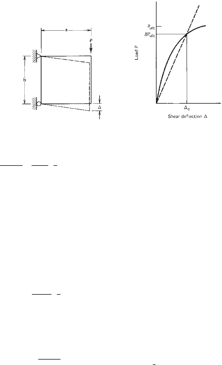
Figure 9.14 Determination of shear rigidity,
¯
Q.
9.55
where the diaphragm shear stiffness of a single wallboard
for a load of 0.8P
ult
is
G
=
0.8P
ult
/b
d
/a
=
0.8P
ult
d
a
b
kips/in. (9.60)
where P
ult
= ultimate load reached in shear diaphragm test
of a given wallboard, kips (Fig. 9.14)
d
= shear deflection corresponding to a load of
0.8P
ult
, in. (Fig. 9.14)
a, b = geometric dimensions of shear diaphragm
test frame, ft (Fig. 9.14)
SF = safety factor, =1.5
The reason for using 0.8P
ult
for G
is that the shear
deflection and thus the shear rigidity at the ultimate load
P
ult
are not well defined and reproducible. A safety factor
of 1.5 was used to avoid premature failure of the wallboard.
By substituting the equation of G
and the safety factor
into Eq. (9.59), the design shear rigidity for wallboards on
both sides of the stud can be evaluated as
¯q =
0.53P
ult
d
a
b
(9.61)
Based on the results of a series of shear diaphragm tests
using different wallboards with No. 6, type S-12, self-
drilling dry-wall screws at 6- to 12-in. (152- to 305-mm)
spacing, some typical values of ¯q
0
have been developed
and were given in Table D4 of the 1980 and 1986 editions
of the AISI Specification. In this table, the value of ¯q
0
was
computed by
¯q
0
=
¯q
2 − s/12
(9.62)
where s is the fastener spacing, in.
In the 1996 edition of the AISI Specification, the equation
for the design shear rigidity
¯
Q for sheathing on both
sides of the wall was rewritten on the basis of a recent
study of gypsum-sheathed cold-formed steel wall studs. In
Ref. 9.108, Miller and Pekoz indicated that the strength of
gypsum wallboard-braced studs was observed to be rather
intensive to stud spacing. Moreover, the deformations of
gypsum wallboard panel (in tension) were observed to be
localized at the fasteners, and not distributed throughout
the panel as in a shear diaphragm. The
¯
Q
o
values listed in
Table D4 were determined from
¯
Q
o
= 12 ¯q
0
, in which the
¯q
0
values were obtained from the 1986 edition of the AISI
Specification. The values given in Table D4 for gypsum are
based on dry service conditions.
In addition to the requirements discussed above, the AISI
specification considers the shear strain requirements as well.
In this regard, Section D4.1(c) specifies that the computed
shear strain γ according to Eq. (9.47) and for a value of
F
n
should not exceed the permissible shear strain of the
wallboard ¯γ given in Table D4 of the specification. From
Eqs. (9.47)–(9.52) it can be seen that the shear strain in
the wallboard is affected by the initial imperfections of
wall studs, for which some minimum values for sweep,
camber, and possible twist of studs are recommended in
Eqs. (9.53)–(9.55) to represent the general practice.
Example 9.2 Use the ASD and LRFD methods to
compute the allowable axial load for the C-section shown
in Fig. 9.15 if it is to be used as wall studs having a length
of 12 ft. Assume that the studs are spaced at every 12 in.
and that
1
2
-in.-thick gypsum boards are attached to both
flanges of the stud. All fasteners are No. 6, type S-12,