Yu W., LaBoube R.A. Cold-Formed Steel Design
Подождите немного. Документ загружается.

COMMENTARY ON APPENDIX 1 (DSM) 375
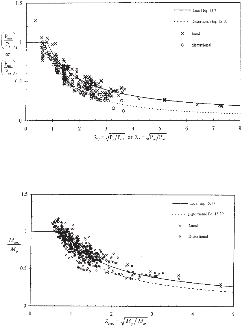
Figure 15.3 Comparison between the test data and the nominal axial strengths calculated by
DSM for concentrically loaded pin-ended columns.
1.346
Figure 15.4 Comparison between the test data and the nominal flexural strengths calculated by
DSM for laterally braced beams.
1.346

376 15 DIRECT-STRENGTH METHOD
15.4 DIRECT-STRENGTH METHOD
DESIGN GUIDE
In order to provide practical and detailed guidance on
the use of the DSM, Schafer prepared the Design Guide
published by AISI in 2006.
1.383
This Guide presents the
basic technical information on elastic buckling analysis
using the finite-strip method, finite-element method, general
beam theory, and manual solutions. The finite-strip method
for cold-formed steel was pioneered at the University of
Sydney and a long-used program (THIN-WALLED) is
commercially available from them. Through partial research
support of AISI, an open-source and free finite-strip method
program (CUFSM) was developed by Professor Schafer at
Johns Hopkins University. A fully commercial implemen-
tation integrated alongside with complete Specification and
member checking is also available as (CFS).
The Guide lists the following three computer programs
for the use of the DSM:
1. CUFSM (www.ce.jhu.edu/bschafer/cufsm)
15.6
2. CFS (www.rsgsoftware.com)
15.7
3. THIN-WALL (www.civil.usyd.edu.au/case/
thinwall.php)
15.4
These programs can provide a proper handling of element
interaction for general cross sections and can be used
to investigate various possible buckling modes, including
local, distortional, and global (overall) buckling for the
design of cold-formed steel structural members. Based
on the computed elastic buckling stresses as shown in
Figs. 4.42 and 5.15 with the full-section properties, the
DSM can be used.
In addition, the Design Guide includes 12 design
examples covering different cold-formed steel cross
sections under various loading and boundary conditions.
Most of the examples are based on those sections used in
the 2002 edition of the AISI Cold-Formed Steel Design
Manual.
1.340
Comparison between the 2001 edition of the
main specification and DSM is summarized in Table 6 of
the Guide. In general, when distortional buckling controls
the design, the DSM provides a relatively lower strength
than the main specification. Since new provisions for
distortional buckling strengths of beams and columns were
added in the 2007 edition of the North American Specifica-
tion, similar capacities can be achieved by using the main
Specification and DSM, if Sections C3.1.4 (b) and C4.2
(b) of the main Specification are used for the design of
flexural members and compression members, respectively.
For numerical comparisons, see Examples II-4 and III-3
of the 2008 edition of the AISI Cold-Formed Steel Design
Manual.
1.349
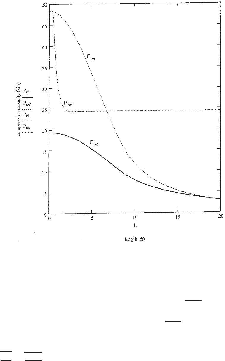
The column chart for the C-section with lips (9CS 2.5
×059) and the beam chart for the same C-section in the
Design Guide are shown here in Figs. 15.5 and 15.6,
respectively, to illustrate the behavior of typical members.
In Fig. 15.5 on the column chart, it is noted that (1)
local buckling dominates the actual column strength, (2)
the reduction due to local buckling is large even for short
columns, and (3) distortional buckling never controls in this
section.
1.383
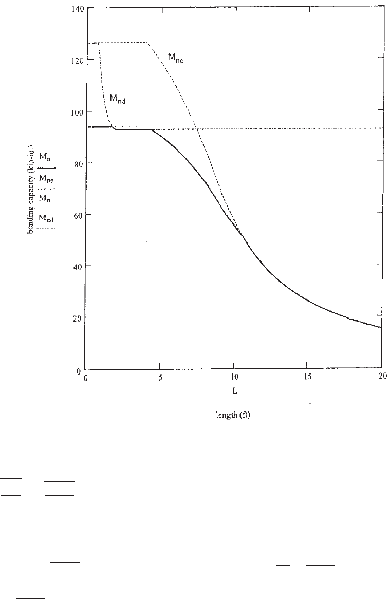
For the beam chart shown in Fig. 15.6, it is noted that
(1) distortional buckling (M
nd
) controls the strength for
a small group of lengths approximately between 2 and
5 ft and (2) beyond approximately 10 ft in length, local
buckling (M
nl
) does not reduce the capacity below the
global buckling strength (M
ne
). (In the parlance of the North
American Specification, this section is fully effective for
unbraced length beyond 10 ft.)
1.383
15.5 DESIGN EXAMPLES
Example 15.1 For the C-section used in Examples 4.2
and 4.13 as a beam member, use the DSM (Section 1.2.2 of
Appendix 1 of the specification) to determine the allowable
moment about the x axis for the ASD method. Assume that
lateral bracing is adequately provided and F
y
= 50 ksi.
SOLUTION
1. Geometric and Material Limitations . As the first step,
the limitations for prequalified beams should be checked by
using Table 1.1.1-2 of Appendix 1 as follows:
h
0
t
=
10.000
0.075
= 133.33 < 321
b
0
t
=
3.500
0.075
= 46.67 < 75
D
t
=
0.720
0.075
= 9.60 < 34
1.5 <
h
0
b
0
=
10.000
3.500
= 2.86
< 17.0
D
b
0
=
0.720
3.500
= 0.21 < 0.70
44
◦
<(θ = 90
◦
) = 90
◦
E
F
y
=
29,500
50
= 590 > 421
Since the given C-section meets the geometric and material
limitations provided in Table 1.1.1-2, use
b
= 1.67 for
ASD as defined in Section 1.2.2 of Appendix 1.
2. Lateral–Torsional Buckling. Since the lateral bracing
is adequately provided, the beam is not subject to lateral–
torsional buckling. According to Section 1.2.2.1 of
DESIGN EXAMPLES 377
Figure 15.5 Column chart for C-section with lips (9CS 2.5 ×059) developed from the DSM.
1.383
Appendix 1, the nominal flexural strength for lateral–
torsional buckling is
M
ne
= M
y
= S
f
F
y
= (4.107)(50) = 205.35 in.-kips
where S
f
= gross section modulus.
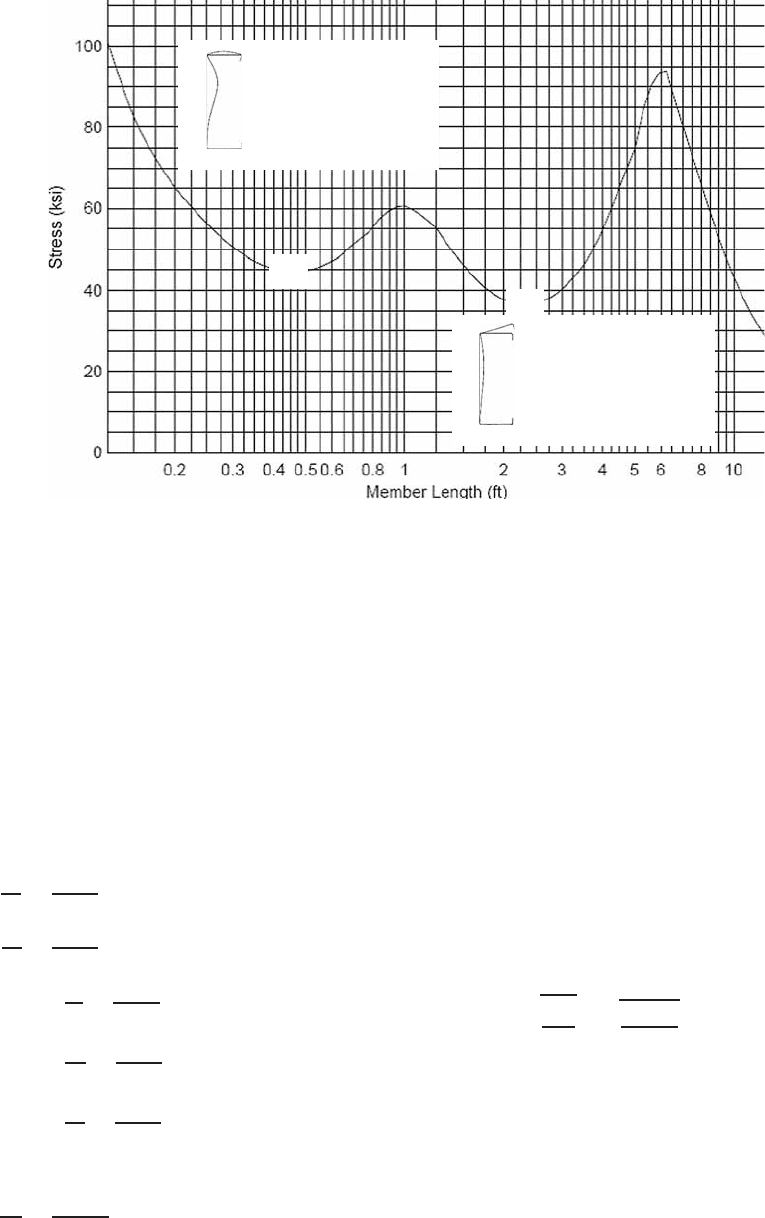
3. Local Buckling. Using the computer program CFS,
15.7
the critical elastic local buckling moment (Fig. 15.7) is
M
crl
= 183.93 in.-kips
From Eq. (15.18),
λ
l
=
M
ne
M
crl
=
205.35
183.93
= 1.057 > 0.776
Based on Eq. (15.17), the nominal flexural strength for local
buckling is
M
nl
=
1 − 0.15
183.93
205.35
0.4
×
183.93
205.35
0.4
(205.35) = 168.29 in.-kips
4. Distortional Buckling. Using the same program
CFS, the critical elastic distortional buckling moment
(Fig. 15.7) is
M
crd
= 151.14 in.-kips
378 15 DIRECT-STRENGTH METHOD
Figure 15.6 Beam chart for C-section with lips (9CS 2.5 ×059) developed from the DSM.
1.383
From Eq. (15.21),
λ
d
=
M
y
M
crd
=
205.35
151.14
= 1.165 > 0.673
Based on Eq. (15.20), the nominal flexural strength for
distortional buckling is
M
nd
=
1 − 0.22
151.14
205.35
0.5
×
151.14
205.35
0.5
(205.35) = 142.92 in.-kips
5. Governing Nominal and Allowable Flexural Strengths.
The governing nominal flexural strength, M
n
, for the given
C-section is the minimum of M
ne
, M
nl
,andM
nd
computed
in items 2, 3, and 4, respectively. Therefore, the nominal
flexural strength is governed by distortional buckling,
that is,
M
n
= 142.92 in.-kips
The allowable moment about the x axis for the ASD
method is
M
a
=
M
n
b
=
142.92
1.67
= 85.58 in.-kips
It should be noted that in Example 4.13 the allowable
moment for the given C-section determined according to
Section C3.1.4 of the main Specification is 82.08 in.-kips.
The allowable moment calculated by the DSM is 4.3%
greater than that using the main specification.
DESIGN EXAMPLES 379
M
crl
= 183.93 in-kips
Local Buckling
X
M
crd
= 151.14 in-kips
Distortional Buckling
X
Figure 15.7 Critical elastic buckling moments for C-section.
Example 15.2 FortheI-sectionusedinExample5.2as
a compression member, use the DSM (Section 1.2.1 of
Appendix 1 of the Specification) to determine the allowable
axial strength for the ASD method. Use K
x
L
x
= 12 ft,
K
y
L
y
= K
t
L
t
= 6ft,andF
y
= 33 ksi. Assume that the
longitudinal spacing for intermediate fasteners is 12 in.
SOLUTION
1. Geometric and Material Limitations. The limitations
for the prequalified column should be checked for the lipped
C-section according to Table 1.1.1-1 of Appendix 1 as
follows
1.345
:
h
0
t
=
8.000
0.075
= 106.67 < 472
b
0
t
=
3.000
0.075
= 40 < 159
4 <
D
t
=
0.700
0.075
= 9.33
< 33
0.7 <
h
0
b
0
=
8.000
3.000
= 2.67
< 5.0
0.05 <
D
b
0
=
0.700
3.000
= 0.23
< 0.41
θ = 90
◦
E
F
y
=
29,500
33
= 894 > 340
Since the above limitations are satisfied with Table 1.1.1-1
of Appendix 1, use
c
= 1.80 for ASD as defined in
Section 1.2.1 of Appendix 1.
2. Flexural, Torsional, or Flexural–Torsional Buckling.
From the computer program CUFSM,
15.6
the minimum
of the critical elastic column buckling loads for flexural,
torsional, or flexural–torsional buckling of the I-section is
the flexural buckling load about the y axis using the modi-
fied slenderness ratio (KL/r)
m
according to Section D1.2
of the North American specification, that is,
P
cre
= 226.02 kips
From Eq. (15.5),
P
y
= A
g
F
y
= (2.24)(33) = 73.92 kips
Based on Eq. (15.4),
λ
c
=
P
y
P
cre
=
73.92
226.02
= 0.572 < 1.5
Using Eq. (15.2),
P
ne
= (0.658
0.572
2
)(73.92) = 64.46 kips
3. Local Buckling. Using the same computer program
CUFSM, the critical elastic local column buckling load
for a single C-section is 15.00 kips. Based on the Design
Guide,
1.383
the critical elastic local column buckling load
380 15 DIRECT-STRENGTH METHOD
for the I-section is twice the single C-section value, that is,
P
crl
= 2(15.00) = 30.00 kips
From Eq. (15.8),
λ
l
=
P
ne
P
crl
=
64.46
30.00
= 1.466 > 0.776
Based on Eq. (15.7),
P
nl
=
1 − 0.15
30.00
64.46
0.4
30.00
64.46
0.4
(64.46)
= 42.23 kips
4. Distortional Buckling. Using the computer program
CUFSM, the critical elastic distortional column buckling
load for a single C-section is 26.89 kips. The critical elastic
distortional column buckling load for the I-section is twice
the single C-section value, that is,
P
crd
= 2(26.89) = 53.78 kips
From Eq. (15.11),
λ
d
=
P
y
P
crd
=
73.92
53.78
= 1.172 > 0.561
Based on Eq. (15.10),
P
nd
=
1 − 0.25
53.78
73.92
0.6
53.78
73.92
0.6
(73.92)
= 48.46 kips
5. Governing Nominal and Allowable Axial Strengths.
The governing nominal axial strength P
n
of the I-section
is the minimum of P
ne
, P
nl
,andP
nd
computed in items 2,
3, and 4, respectively. Therefore,
P
n
= 42.23 kips
The allowable axial load for the ASD method is
P
a
=
P
n
c
=
42.23
1.80
= 23.46 kips
Compared with the allowable load of 25.59 kips computed
in Example 5.2, the allowable load determined by the DSM
is 7.2% smaller than that using the main Specification.
During the past few years, numerous design examples
have been prepared and published in various publications
using the DSM. For additional examples, see the Design
Guide,
1.383
the Design Manual,
1.349
and the engineering
magazine.
15.23

APPENDIX A
Thickness of Base Metal
For uncoated steel sheets, the thickness of the base metal
is listed in Table A.1. For galvanized steel sheets, the
thickness of the base metal can be obtained by subtracting
the coating thickness in Table A.2 for the specific
Table A.1 Thicknesses of Uncoated and Galvanized
Steel Sheets
a
Uncoated Sheet Galvanized Sheet
Equivalent
Gage Weight, Thickness, Weight, Thickness,
b,c
Number
b
(lb/ft
2
) (in.) (lb/ft
2
)(in.)
3 10.000 0.2391
4 9.375 0.2242
5 8.750 0.2092
6 8.125 0.1943
7 7.500 0.1793
8 6.875 0.1644 7.031 0.1681
9 6.250 0.1495 6.406 0.1532
10 5.625 0.1345 5.781 0.1382
11 5.000 0.1196 5.156 0.1233
12 4.375 0.1046 4.531 0.1084
13 3.750 0.0897 3.906 0.0934
14 3.125 0.0747 3.281 0.0785
15 2.813 0.0673 2.969 0.0710
16 2.500 0.0598 2.656 0.0635
17 2.250 0.0538 2.406 0.0575
18 2.000 0.0478 2.156 0.0516
19 1.750 0.0418 1.906 0.0456
20 1.500 0.0359 1.656 0.0396
21 1.375 0.0329 1.531 0.0366
22 1.250 0.0299 1.406 0.0336
23 1.125 0.0269 1.281 0.0306
24 1.000 0.0239 1.156 0.0276
25 0.875 0.0209 1.031 0.0247
Table A.1 (continued )
Uncoated Sheet Galvanized Sheet
Equivalent
Gage Weight, Thickness, Weight, Thickness,
b,c
Number
b
(lb/ft
2
) (in.) (lb/ft
2
)(in.)
26 0.750 0.0179 0.906 0.0217
27 0.688 0.0164 0.844 0.0202
28 0.625 0.0149 0.781 0.0187
29 0.563 0.0135 0.719 0.0172
30 0.500 0.0120 0.656 0.0157
Note: 1lb/ft
2
= 47.88 N/m
2
;1in.= 25.4 mm.
a
Based on AISI and the Iron and Steel Society steel products
manual.
A.1,A.5
b
For uncoated sheets, use manufacturers’ standard gage number;
for g alvanized sheets, use galvanized sheet gage number.
c
The equivalent thickness for galvanized sheet includes both the
base metal and th e coating on both surfaces. All listed val ues are
based on a coating thickness of 0.0037 in., which is for the coating
designation of G210.
coating designation from the equivalent thickness listed in
Table A.1.
In the past, gage numbers have been used to specify
sheet steel thickness, but modern practice is to use decimal
values for thickness. For reference purposes, Table A.1 lists
gage numbers as well as the thicknesses of uncoated and
galvanized steel sheets.
In 1999, the North American Steel Framing Alliance
(NASFA) announced a new universal designator s ystem for
cold-formed steel framing members. This system uses the
minimum base metal thicknesses, which represents 95% of
the design thickness according to Section A3.4 of the AISI
Specification
A.3,A.4
or Section A2.4 of the North American
specification.
1.336, 1.345
Table A.2 Coating Thickness to Be Deducted from
the Equivalent Thickness of Galvanized Sheets
Coating Coating Weight, Approximate Coating
Designation (oz/ft
2
) Thickness (in.)
G235 2.35 0.0040
G210 2.10 0.0036
G185 1.85 0.0032
G165 1.65 0.0028
G140 1.40 0.0024
G115 1.15 0.0020
G90 0.90 0.0015
G60 0.60 0.0010
Note: 1oz/ft
2
= 3N/m
2
;1in.= 25.4 mm.
Based on standard specification for ASTM A653, 1997.
381
APPENDIX B
Torsion
B.1 I NTRODUCTION
For beam design, when the transverse loads do not pass
through the shear center of the cross section, the member
will be subject to a c ombination of plane bending and
torsional moment. Consequently, the following longitu-
dinal stresses (perpendicular to the cross section) and shear
stresses (in the plane of the cross section) will be developed
in the member:
1. Due to Plane Bending
f = longitudinal bending stress
v = shear stress
2. Due to Torsion
σ
w
= warping longitudinal stress
τ
t
= pure torsional shear stress (or St. Venant shear
stress)
τ
w
= warping shear stress
The torsional analysis of rolled s teel sections has been
well presented in Refs. B.1, 2.45, and 4.140. Many text-
books on steel structures and mechanics also treat this
subject in detail. In general, the longitudinal and shear
stresses due to plane bending and torsional moment are
computed separately and then combined for the final results.
This appendix covers the location of the shear center and
summarizes the methods used for determining torsional
stresses. For a detailed discussion and the derivation of
formulas, the reader is referred to Refs. B.1, 2.45, 4.140,
and other publications.
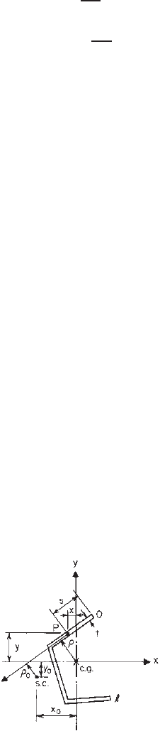
B.2 SHEAR CENTER
For any open shapes as shown in Fig. B.1, the shear
center of the cross section can be located by x
0
and y
0
as follows
2.45,1.159
:
x
0
=
I
ωy
I
x
(B.1)
y
0
=−
I
ωx
I
y
(B.2)
where x
0
= x coordinate of shear center
y
0
= y coordinate of shear center
I
x
,I
y
= moments of inertia of cross section about
x-andy-axes, respectively
I
ωy
=
l
0
ωyt d s (B.3)
I
ωx
=
l
0
ωxt ds (B.4)
ω =
s
0
ρds (B.5)
where t = wall thickness
x,y = coordinates measured from centroid to any
point P located on middle line of cross section
s = distance measured along middle line of cross
section from one end to point P
l = total length of middle line of cross section
ρ = perpendicular distance to tangent line from
centroid (c.g.). The magnitude of ρ is positive
if the centroid is to the left of an observer
standing at P and looking toward the positive
direction of the tangent.
Since cold-formed sections are usually composed of flat
elements, the computation of the above properties (I
ωx
, I
ωy
,
Figure B.1 Location of the shear center (s.c.) for open section.
383
384 B TORSION
Figure B.2 Notations for computing I
ωx
,I
ωy
and ω.
and ω) can be simplified as follows by using the notations
shown in Fig. B.2
2.45
:
ω
j
=
i=j −1
i=0
ρ
i,i+1
b
i,i+1
(B.6)
I
ωx
=
1
3
i=n−1
i=0
(ω
i
x
i
+ ω
i+1
x
i+1
)t
i,i+1
b
i,i+1
+
1
6
i=n−1
i=0
(ω
i
x
i+1
+ ω
i+1
x
i
)t
i,i+1
b
i,i+1
(B.7)
I
ωy
=
1
3
i=n−1
i=0
(ω
i
y
i
+ ω
i+1
y
i+1
)t
i,i+1
b
i,i+1
+
1
6
i=n−1
i=0
(ω
i
y
i+1
+ ω
i+1
y
i
)t
i,i+1
b
i,i+1
(B.8)
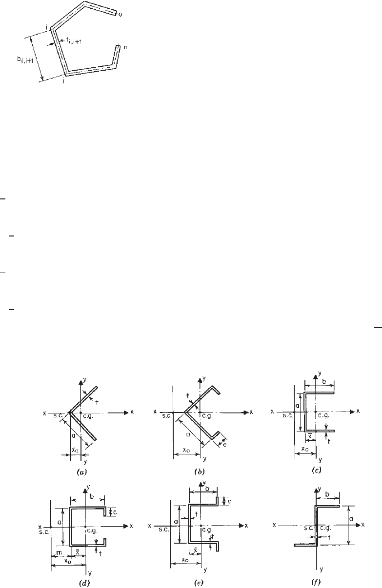
Table B.1 includes values of x
0
and y
0
for e qual-leg
angles, channels, hat sections, and Z-sections (Fig. B.3).
All equations are based on square corners. Reference 1.159
contains some general equations based on round corners for
area and moment of inertia. If the equations in Table B.1
are to be used to compute the values of x
0
, the error is
usually less than 5%, except that a slightly larger error
may be expected for angle sections. See the AISI Design
Manual
1.349
for additional information.
B.3 TORSIONAL STRESSES
As mentioned in Section B.1, when a torsional moment M
t
is applied to the beam, as shown in Fig. B.4, the member is
subject to warping longitudinal stress, pure torsional shear
stress, and warping shear stress.
B.3.1 Warping Longitudinal Stress σ
w
The warping longitudinal s tress developed in the beam
flange can be computed by using Eq. (B.9). It is constant
across the thickness of the beam flange. The distribution
of the longitudinal stresses a long the flange is shown in
Fig. B.5.
σ
w
= Eω
n
φ
(B.9)
where E = modulus of elasticity, 29.5 × 10
3
ksi
(203 GPa, or 2.07 × 10
6
kg/cm
2
)
ω
n
= normalized unit warping, =
1
A
l
0
ω
0
tds− ω
0
(B.10)
Figure B.3 Sections used in Table B.1.