Yu W., LaBoube R.A. Cold-Formed Steel Design
Подождите немного. Документ загружается.

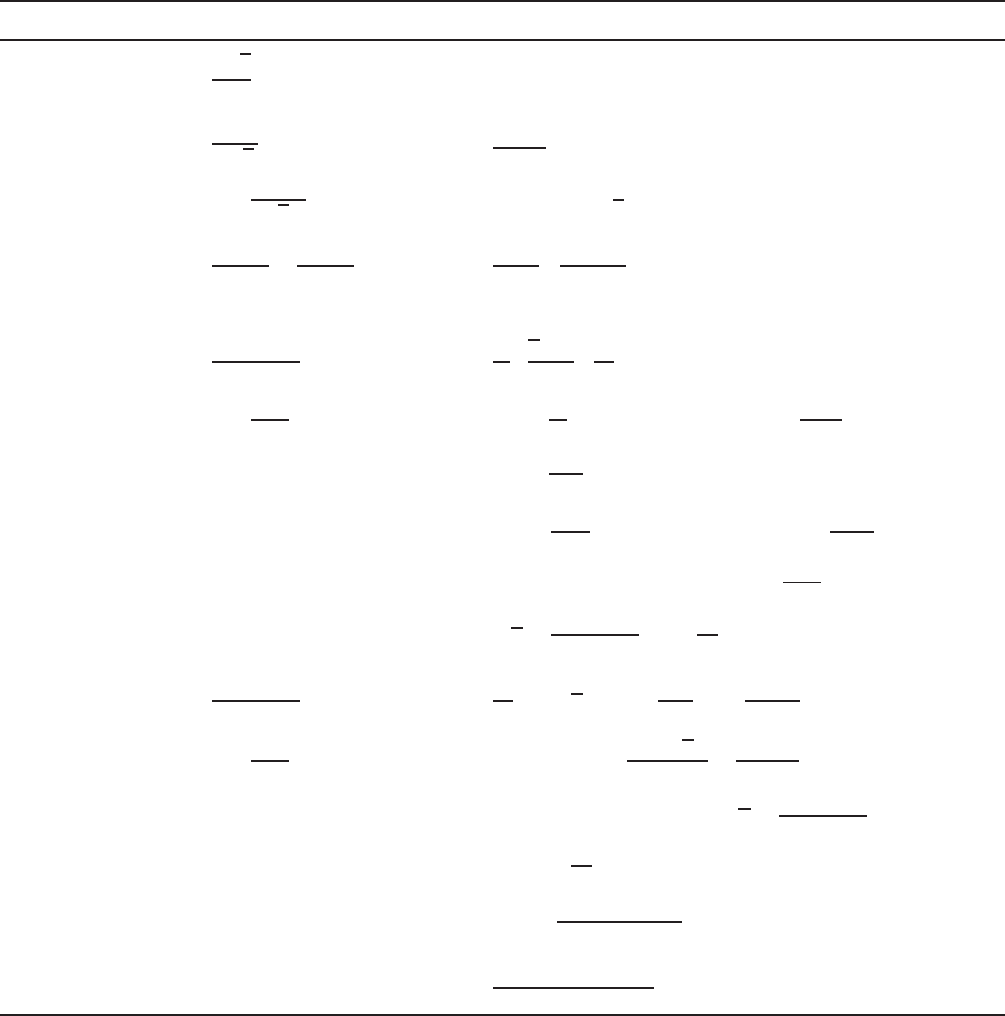
TORSIONAL STRESSES 385
Table B.1 Values of x
0
,y
0
,andC
w
for Angles, Channels, Hat Sections, and Z-Sections
Section x
0
y
0
C
w
Equal-leg angle
without stiffening
lips (Fig. B.3a)
a
√
2
4
00
Equal-leg angle
with stiffening
lips (Fig. B.3b)
a + c
2
√
2
0
t
2
a
4
c
3
18I
x
(4a + 3c)
+
tac
2
3
√
2I
x
(3a − 2c) where I
x
=
t
3
(a
3
+ c
3
+ 3a
2
c − 3ac
2
)
Channel with
unstiffened
flanges
(Fig. B.3c)
b
2
a + 2b
+
3b
2
6b + a
0
ta
2
b
3
12
3b + 2a
6b + a
Channel with
stiffened flanges
(Fig. B.3d)
bt(b + 2c)
A
0
t
2
A
xAa
2
t
b
2
3
+ m
2
− mb
+
bt
12I
x
(6ca
2
+
A
3t
m
2
a
3
+ b
2
c
2
(
2c + 3a
)
−
I
x
m
2
t
(
2a + 4c
)
+3ba
2
− 8c
3
) +
mc
2
3
8b
2
c + 2m
[
2c
(
c − a
)
+ b
(
2c − 3a
)
]
+
b
2
a
2
6
(
3c + b
)(
4c + a
)
− 6c
2
−
m
2
a
4
4
where A = (a + 2b + 2c)t, m =
bt
12I
x
(6ca
2
+ 3ba
2
− 8c
3
,
x =
bt(b + 2c)
A
,I
x
=
t
12
(a
3
+ 6ba
2
+ 6ca
2
− 12ac
2
+ 8c
3
)
Hat section
(Fig. B.3e)
bt(b + 2c)
A
0
a
2
4
I
y
+ x
2
A
1 −
a
2
A
4I
x
+
2b
2
tc
3
3
+
bt
12I
x
(6ca
2
−ab
2
c
2
t +
a
2
btc
3
xA
3I
x
−
4b
2
t
2
c
6
9I
x
+3a
2
b − 8c
3
) where A = (a + 2b + 2c)t, x =
bt(2c + b)
A
I
x
=
t
12
(a
3
+ 6ba
2
+ 6ca
2
+ 12ac
2
+ 8c
3
)
I
y
=
tb
2
3(a + 2b + 2c)
(2ab + b
2
+ 4bc + 6ca)
Z-section
(Fig. B.3f )
00
(tb
3
a
2
/12)(b + 2a)
2b + a
Notes:
1. Values of a, b,andc are middle-line dimensions.
2. In this table, some formulas are obtained from Ref. B.2.
3. For other sections, see Section 3 of the AISI Manual for Cold-Formed Steel Design.
1.349
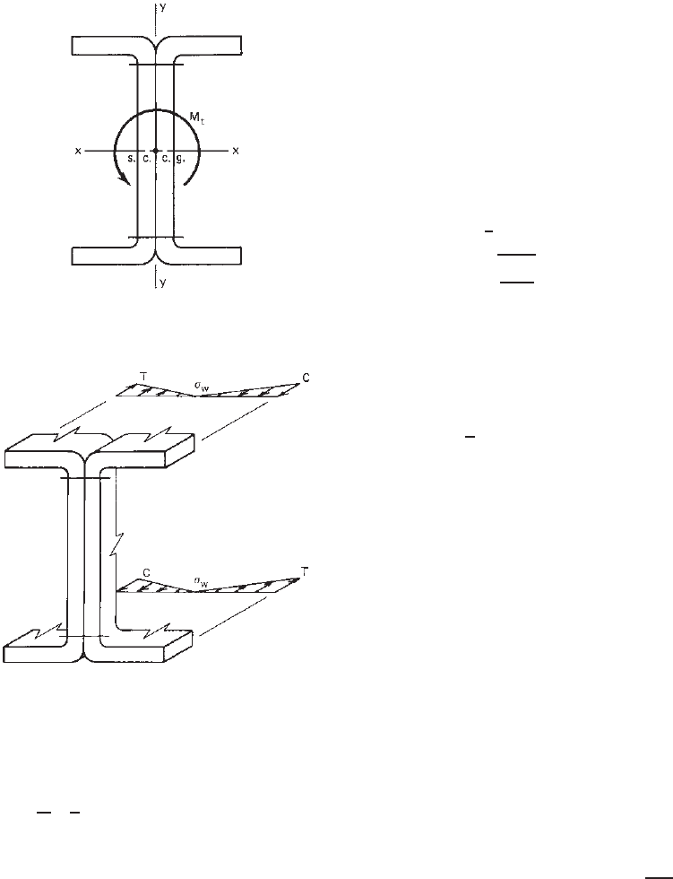
386 B TORSION
Figure B.4 Torsional moment applied to an I-beam.
Figure B.5 Distribution of the warping longitudinal stresses in
beam flanges.
or
(ω
n
)
j
=
1
A
1
2
i=n−1
i=0
[(ω
0
)
i
+ (ω
0
)
i+1
]t
i,i+1
b
i,i+1
− (ω
0
)
j
(B.11)
ω
0
=
s
0
ρ
0
ds (B.12)
or
(ω
0
)
j
=
i=j −1
i=0
(
ρ
0
)
i,i+1
b
i,i+1
(B.13)
where A = total area of cross section
ρ
0
= perpendicular distance to tangent line from
shear center (s.c.) (Fig. B.1). The magnitude of
ρ
0
is positive if the shear center is to the left
of an observer standing at P and looking
toward the positive direction of the tangent.
φ
= second derivative of angle of rotation φ with
respect to z . Several typical equations for the
angle of rotation φ are given in Table B.2.
In Table B.2, the shear modulus G = 11.3 × 10
3
ksi
(78 GPa, or 794 × 10
3
kg/cm
2
) and J is the St. Venant
torsion constant of cross section. For thin-walled sections
composed of n segments of uniform thickness,
J =
1
3
(l
1
t
3
1
+ l
2
t
3
2
+···+l
i
t
3
i
+···+l
n
t
3
n
) (B.14)
λ =
GJ
EC
w
(B.15)
and the warping constant of torsion of the cross section is,
C
w
=
l
0
ω
2
n
tds (B.16)
or
C
w
=
1
3
i=n−1
i=0
[(ω
n
)
2
i
+ (ω
n
)
i
(ω
n
)
i+1
+ (ω
n
)
2
i+1
]t
i,i+1
b
i,i+1
(B.17)
The values of C
w
for angles, channels, hat sections, and
Z-sections are a lso included in Table B.1. All equations
are based on square corners. These C
w
values are used
for determining torsional stresses and for the design of
singly symmetric and point-symmetric sections to be used
as compression members.
B.3.2 Pure Torsional Shear Stress τ
t
The maximum pure torsional shear stress parallel to the
edge of the element can be computed by using Eq. (B.18)
or Eq. (B.19). These shear stresses vary linearly across the
thickness of each element of the cross sections, as shown
in Fig. B.6:
τ
t,max
= Gtφ
(B.18)
or
τ
t,max
=
M
t
t
J
(B.19)
where M
t
= torsional moment
φ
= first derivative of angle of rotation φ with
respect to z
B.3.3 Warping Shear Stress τ
w
The warping shear stress can be computed by using
Eq. (B.20). These shear stresses act in the direction parallel
to the edge of the element. As shown in Fig. B.7, they are
constant across the thickness of an element of the cross
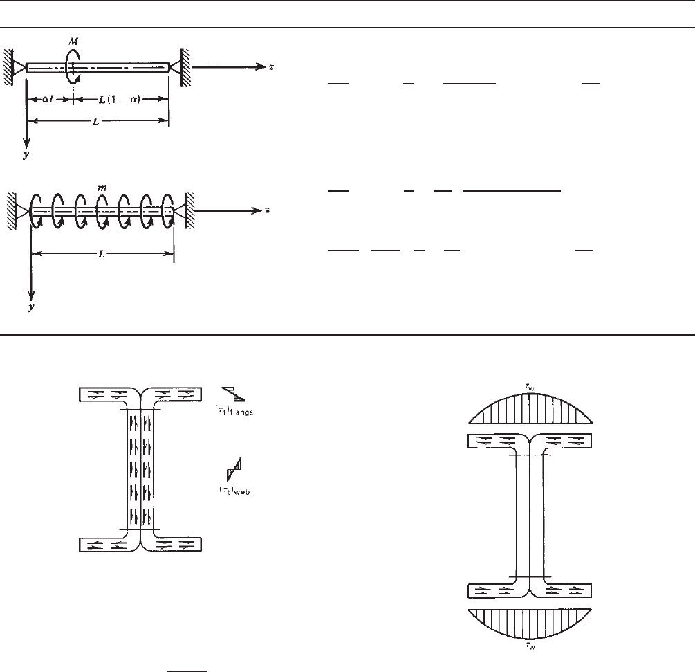
TORSIONAL STRESSES 387
Table B.2 Equations for Angle of Rotation (for Beams with Pinned Ends)
B.1
Loading Condition φ
For 0 ≤ z ≤ αL,
φ =
ML
GJ
(1 − α)
z
L
+
sinh λαL
tanh λL
− cosh λαL
1
λL
sin λz
For αL ≤ zL,
φ =
ML
GJ
(L − z)
α
L
+
1
λL
sinh λαL sinh λz
tanh λL
− sinh λαL cosh λz
φ =
m
GJλ
2
λ
2
L
2
2
z
L
−
z
2
L
2
+ cosh λz − tanh
λL
2
sinh λz − 1
Note: For other loadings and boundary conditions, see Ref. B.1.
Figure B.6 Pure torsional shear stresses in the cross-section.
section. The maximum stress occurs at the midwidth of the
flange,
τ
w
=−
ES
ω
φ
t
(B.20)
where the warping static moment at point P, shown in
Fig. B.1, is given a
S
ω
=
s
0
ω
n
tds (B.21)
and φ
is the third derivative of the angle of rotation φ
with respect to z .
It should be noted that torsional stresses are determined
by material properties (E and G ), torsional properties
Figure B.7 Distribution of the warping shear stresses in beam
flanges.
(ω
n
, S
ω
, J, and C
w
), cross-sectional dimensions, and deriva-
tives of the angle of rotation. Torsional properties vary
in the cross section, and derivatives of the angle of rota-
tion change along the length of the member. Therefore,
a study should be made on the combination of plane
bending stresses and torsional stresses along the length of
the member with due consideration given to the direction
of stress.
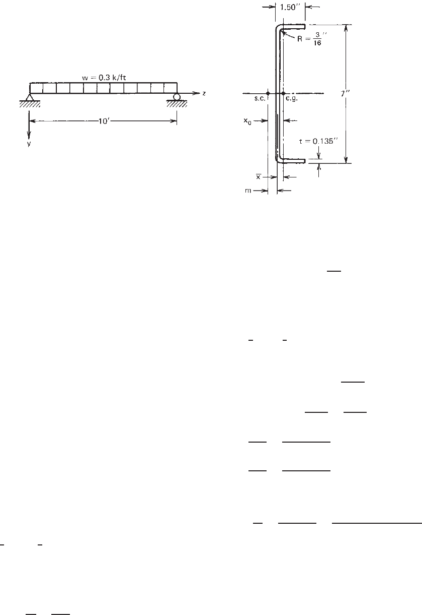
388 B TORSION
Figure B.8 Example B.1.
Example B.1 For the beam (channel section) shown in
Fig. B.8, determine the maximum longitudinal stress and
shear stress under the following two loading conditions:
A. Uniform load applied through shear center (s.c.)
B. Uniform load applied through centroid (c.g.)
Use E = 29,500 ksi and G = 11,300 ksi. Assume that both
ends of the beam are simply supported flexurally and
torsionally.
SOLUTION
A. Uniform Load Applied through Shear Center (s.c.).
Since the uniform load is applied through the shear center
of the cross section, the beam is subject only to the plane
bending without the torsional moment.
1. Sectional Properties. Based on the methods discussed in
the text, the following full sectional properties can be
computed:
I
x
= 7.84 in.
4
S
x
= 2.24 in.
3
2. Longitudinal Stress. The maximum bending moment at
midspan is
M =
1
8
wL
2
=
1
8
(0.3)(10
2
) = 3.75 ft-kips
= 45 in.-kips
The maximum longitudinal bending stress in the
flange is
f =
M
S
x
=
45
2.24
= 20.1ksi
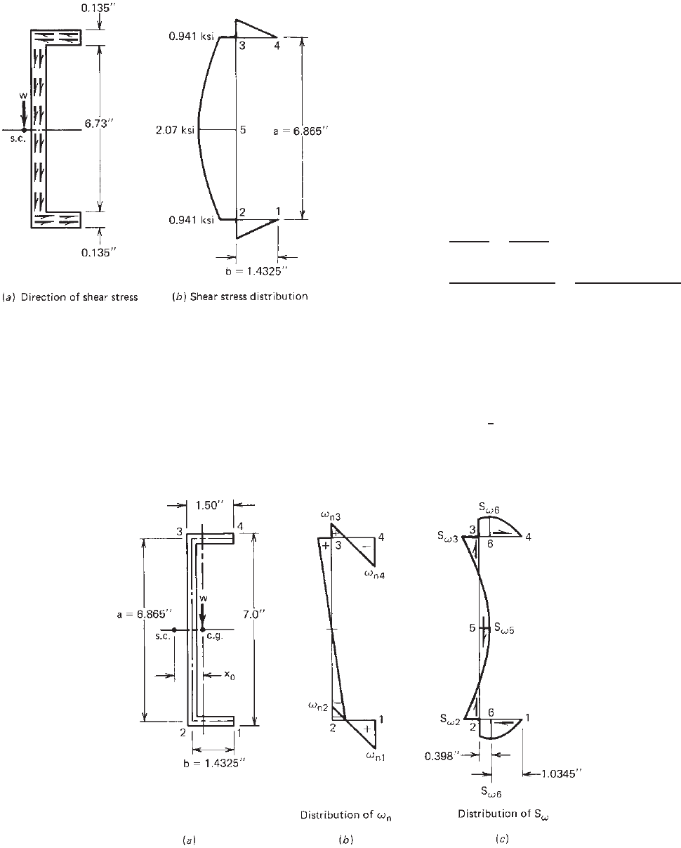
3. Shear Stress. As discussed in Section 4.3.3.1, the shear
stress v due to plane bending can be computed by
v =
VQ
I
x
t
Therefore, as shown in Fig. B.9, the maximum s hear
stresses developed in the beam flange and the web are
computed as follows:
V =
1
2
wL =
1
2
(0.3)(10) = 1.5kips
Q
1
= Q
4
= 0
Q
2
= Q
3
= 1.4325(0.135)
6.865
2
= 0.664 in.
3
Q
5
= Q
2
+ 0.135
6.865
2
6.865
4
= 1.459 in.
3
v
2
=
VQ
2
I
x
t
=
1.5(0.664)
7.84(0.135)
= 0.941 ksi
v
5
=
VQ
5
I
x
t
=
1.5(1.459)
7.84(0.135)
= 2.07 ksi
By using the average stress method,
v
av
=
V
ht
=
V
(d − 2t)t
=
1.5
[7 − 2(0.135)](0.135)
= 1.65 ksi
It can be seen that for this channel section the value of v
5
is approximately 25% higher than the average value v
av
.
B. Uniform Load Applied through Centroid (c.g.). When
the uniform load is applied through the centroid, as shown
in Fig. B.10a, the beam is subject to plane bending and a
TORSIONAL STRESSES 389
Figure B.9 Shear stresses due to plane bending.
uniformly distributed torque because for the given channel
section the shear center and the centroid do not coincide.
In order to compute the longitudinal stress and the shear
stresses developed from the torsional moment, the shear
center should be located and torsional properties such as
J , C
w
, ω
n
,andS
ω
should be computed by using full
section dimensions. In addition, the equation for the angle
of rotation φ and its derivatives must also be derived and
evaluated.
The following calculations are based on the procedures
given by Galambos in Ref. 2.45:
1. Location of Shear Center. Based on the midline
dimensions shown in Fig. B.10a, the shear center of
the given channel section can be located by using
the value of x
0
computed from the equation given in
Table B.1 for channels with unstiffened flanges:
x
0
=
b
2
a + 2b
+
3b
2
6b + a
=
(1.4325)
2
6.865 + 2(1.4325)
+
3(1.4325)
2
6(1.4325) + 6.865
= 0.609 in.
2. Torsional Properties. By using the midline dimen-
sions, the torsional properties can be computed as
follows:
a. St. Venant Torsion Constant. From Eq. (B.14)
J =
1
3
[2(1.4325) +6.865](0.135)
3
= 0.008 in.
4
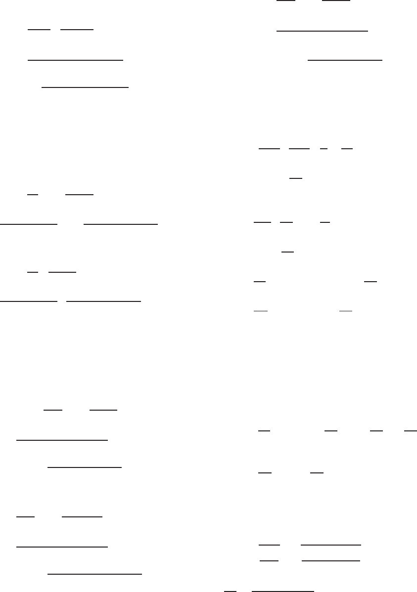
Figure B.10 Torsional properties ω
n
and S
ω
.
390 B TORSION
b. Warping Constant of Torsion. From Eq. (B.17) or
the equation given in Table B .1,
C
w
=
ta
2
b
3
12
3b + 2a
6b + a
=
0.135(6.865)
2
(1.4325)
3
12
×
3(1.4325) + 2(6.865)
6(1.4325) + 6.865
= 1.817 in.
6
c. Normalized Warping Constant. From Eqs.
(B.10)–(B.13) or using the equations given in
Ref. 2.45 for channels, the values of ω
n1
through
ω
n4
showninFig.B.10b can be computed:
ω
n1
= ω
n4
=
ab
2
1 −
3b
6b + a
=
6.865(1.4325)
2
1 −
3(1.4325)
6(1.4325) + 6.865
= 3.550 in.
2
ω
n2
= ω
n3
=
ab
2
3b
6b + a
=
6.865(1.4325)
2
3(1.4325)
6(1.4325) + 6.865
= 1.367 in.
2
d. Warping Static Moment. From Eq. (B.21) or using
the equations given in R ef. 2.45, the values of S
ω2
,
S
ω3
, S
ω5
,andS
ω6
asshowninFig.B.10c can be
computed:
S
ω2
= S
ω3
=
ab
2
t
4
1 −
6b
6b + a
=
6.865(1.4325)
2
(0.135)
4
×
1 −
6(1.4325)
6(1.4325) + 6.865
= 0.211 in.
4
S
ω5
=
ab
2
t
4
1 −
6b + 1.5a
6b + a
=
6.865(1.4325)
2
(0.135)
4
×
1 −
6(1.4325) + 1.5(6.865)
6(1.4325) + 6.865
=−0.106 in.
4
S
ω6
=
ab
2
t
4
1 −
3b
6b + a
2
=
6.865(1.4325)
2
(0.135)
4
×
1 −
3(1.4325)
6(1.4325) + 6.865
2
= 0.248 in.
4
3. Equation of Angle of Rotation and Its Derivatives.
From Table B.2, the following equation can be used
for the angle of rotation:
φ =
m
GJλ
2
λ
2
L
2
2
z
L
−
z
2
L
2
+ cosh λz
−tanh
λL
2
sinh λz − 1
The derivatives with respect to z are as follows:
φ
=
m
GJλ
λL
2
1 −
2z
L
+ sinh λz
−tanh
λL
2
cosh λz
φ
=
m
GJ
−1 + cosh λz − tanh
λL
2
sinh λz
φ
=
mλ
GJ
sinh λz − tanh
λL
2
cosh λz
4. Warping Longitudinal Stress. The warping longitu-
dinal stress can be computed by using Eq. (B.9):
σ
w
= Eω
n
φ
a. At z = 0,
φ
= 0 σ
w
= 0
b. At z = L/2,
φ
=
m
GJ
−1 + cosh
λL
2
− tanh
λL
2
sinh
λL
2
where
m =
0.3
12
x
0
=
0.3
12
(0.609)
= 0.0152 in.-kips /in.
G = 11,300 ksi
J = 0.008 in.
4
λ =
GJ
EC
w
=
11,300(0.008)
29,500(1.817)
= 0.0411 in.
−1
λL
2
=
0.0411(10)(12)
2
= 2.466
TORSIONAL STRESSES 391
Therefore,
φ
=
0.0152
11, 300(0.008)
× [−1 + cosh(2.466)
− tanh(2.466) sinh(2.466)]
=−0.0001398 in.
−2
By using E = 29,500 ksi and the values of ω
nl
through ω
n4
given in Fig. B.10b, the warping longi-
tudinal s tresses at z = L/2 for points 1–4 shown in
Fig. B.10a are computed:
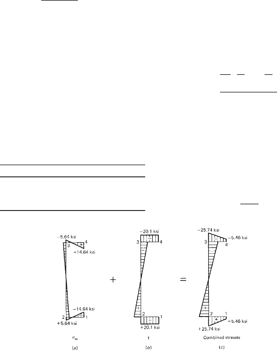
σ
w1
= Eω
n1
φ
= 29,500(3.550)(−0.0001398) =−14.64 ksi
σ
w2
= 29,500(−1.367)(−0.0001398) = 5.64 ksi
σ
w3
= 29,500(1.367)(−0.0001398) =−5.64 ksi
σ
w4
= 29,500(−3.550)(−0.0001398) = 14.64 ksi
The distribution of σ
w
is shown in Fig. B.11a.
5. Combined Longitudinal Stress. From case A of this
problem, the distribution of the longitudinal stress f
due to plane bending is shown in Fig. B .11b.The
longitudinal stresses are combined in the following
table:
Point σ
w
(ksi) f (ksi) σ
w
+ f (ksi)
1 −14.64 +20.10 +5.46
2 +5.64 +20.10 +25.74
3 −5.64 −20.10 −25.74
4 +14.64 −20.10 −5.46
The combined longitudinal stresses are shown in
Fig. B.11c. The maximum longitudinal stress of
25.74 ksi is 28% higher than the longitudinal stress
due to plane bending.
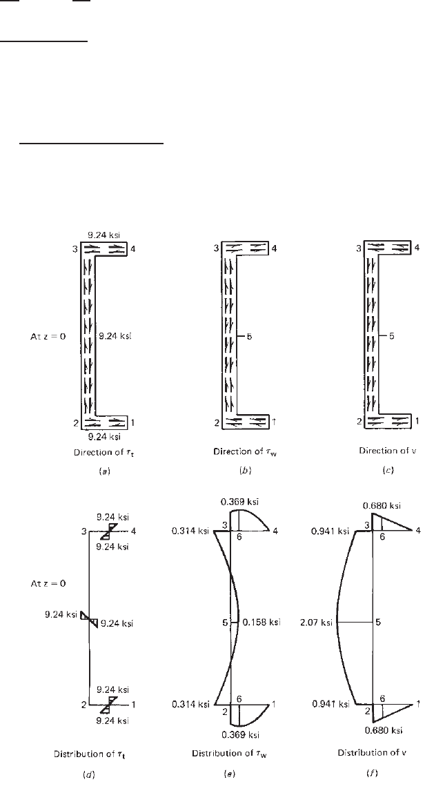
6. Shear Stresses Due to Torsion
a. Pure Torsional Shear Stress. By using Eq. (B.18),
the pure torsional shear stress is
τ
t
= Gtφ
At z = 0,
φ
=
m
GJλ
λL
2
− tanh
λL
2
=
0.0152
11,300(0.008)(0.0411)
× [2.466 − tanh(2.466)]
= 0.00606 in.
−1
Therefore, the pure torsion shear stress in flanges
andthewebis
τ
t
= Gtφ
= 11,300(0.135)(0.00606) = 9.24 ksi
The distribution of τ
t
is shown in Figs. B.12a and
d.
b. Warping Shear Stress. By using Eq. (B.20), the
warping shear stress is
τ
w
=
ES
ω
φ
t
Figure B.11 Distribution of longitudinal stresses.
392 B TORSION
At z = 0,
φ
=
mλ
GJ
−tanh
λL
2
=
0.0152(0.0411)
11,300(0.008)
[−tanh(2.466)]
=−6.81 × 10
−6
in.
−3
Therefore, the warping shear stress is
τ
w
=−
29,500S
ω
(−6.81 × 10
−6
)
0.135
= 1.488S
ω
Using the values of S
ω
given in Fig. B.10c,
τ
w1
= 0
τ
w2
= τ
w3
= 1.488(0.211) = 0.314 ksi
τ
w5
= 1.488(−0.106) =−0.158 ksi
τ
w6
= 1.488(0.248) = 0.369 ksi
The distribution of τ
w
is given in Figs. B.12b
and e.
7. Combined Shear Stresses. The combined shear
stresses at z = 0 can be summarized in the following
Figure B.12 Distribution of shear stresses.
DESIGN CRITERIA FOR COMBINED B ENDING AND TORSIONAL LOADING 393
table, in which the shear stress v due to plane bending
is obtained from case A:
Point τ
t
(ksi) τ
w
(ksi) v (ksi) τ
total
(ksi)
69.24 0.369 ← 0.680 → 9.551 →
29.24 0.314 ← 0.941 → 9.867 →
59.24↑↓ 0.158 ↓ 2.070 ↓ 11.468 ↓
The maximum shear stress of 11.468 ksi occurs
at point 5, which is the neutral axis of the channel
section.
For additional information on torsional analysis, see Refs.
B.3 and B.4.
B.4 DESIGN CRITERIA FOR COMBINED
BENDING AND TORSIONAL LOADING
Section B.3 discussed the methods for determining the
torsional stresses including warping longitudinal stress,
pure torsional shear stress, and warping shear stress. The
computations of these torsional stresses are illustrated in
Example B.1 for a channel section. This design example
also includes the combined longitudinal s tress and the
combined shear stress resulting from plane bending and
torsional moment.
In the 2007 edition of the North American specifica-
tion, newly developed design provisions are included in
Section C3.6. It states that for laterally unrestrained flexural
members subjected to both bending and torsional loading
the available flexural strength calculated in accordance with
Section 4.2.2.1 in this volume shall be reduced by multi-
plying it by a reduction factor, R, determined by Eq. (B.22)
at the point of maximum combined stress on the cross
section:
R =
f
f + σ
w
= 1.0 (B.22)
where f = longitudinal bending stress calculated by using
effective section properties
σ
w
= warping longitudinal stress calculated by
using full sectional properties
For C-sections with edge-stiffened flanges, if the
maximum compressive stresses occur at the junction of
web and flange, the R factor shall be permitted to be
increased by 15%, but the R factor shall not be greater
than 1.0.
The provisions of Section C3.6 of the North American
Specification shall not be applied for flexural members
having one flange through fastened to deck, sheathing, or a
standing seam roof system.
The above-mentioned design provisions are supported by
the tests on channels conducted by Winter, Lansing, and
McCalley in 1949
4.108
and the study on bending and torsion
of channel beams by Put, Pi, and Trahair in 1999.
4.189
It should be noted that in Example B.1 no torsional
bracing was used for the given channel section. If the
midspan bracing or the third-point bracing is used, the
calculation of the R value is demonstrated in Example II-10
of the 2008 edition of the AISI design Manual.
1.349